8C OWNER’S MANUAL U.S.A.
E EMU01448 TO THE OWNER Thank you for choosing a Yamaha outboard motor. This Owner’s manual contains information needed for proper operation, maintenance and care. A thorough understanding of these simple instructions will help you obtain maximum enjoyment from your new Yamaha. If you have any question about the operation or maintenance of your outboard motor, please consult a Yamaha dealer. In this Owner’s Manual particularly important information is distinguished in the following ways.
EMA20010 CONTENTS E GENERAL INFORMATION 1 BASIC COMPONENTS 2 OPERATION 3 MAINTENANCE 4 TROUBLE RECOVERY 5 INDEX 6 READ THIS OWNER’S MANUAL CAREFULLY BEFORE OPERATING YOUR OUTBOARD MOTOR.
E EMB00010 Chapter 1 GENERAL INFORMATION IDENTIFICATION NUMBERS RECORD ....................................................1-1 1 2 EMISSION CONTROL INFORMATION...1-2 SAFETY INFORMATION..........................1-3 IMPORTANT LABELS ..............................1-5 3 BASIC BOATING RULES .........................1-6 FUELING INSTRUCTIONS.....................1-10 Gasoline(petrol) ..................................1-11 Engine oil .............................................1-11 PROPELLER SELECTION .......
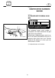
E EMU00005 IDENTIFICATION NUMBERS RECORD EMU00007 OUTBOARD MOTOR SERIAL NUMBER M B K INDUSTRIE PRODUCT ASSEMBLED IN FRANCE PRODUIT ASSEMBLE EN FRANCE 1 401012 The outboard motor serial number is stamped on the label attached to the port side of the clamp-bracket. Record your outboard motor serial number in the spaces provided to assist you in ordering spare parts from your Yamaha dealer or for reference in case your outboard motor is stolen.
E EMU01385 EMISSION CONTROL INFORMATION q w EMU01386 NORTH AMERICAN MODELS This engine conforms to U.S. Environmental Protection Agency (EPA) regulations for marine SI engines. See the label affixed to your engine for details. Approval label of Emission control certificate This label is attached to the bottom cowling. 1 Emission control information label EMISSION CONTROL INFORMATION ENGINE FAMILY : THIS ENGINE CONFORMS TO 2001 U.S. EPA REGULATIONS FOR MARINE SI ENGINES.
E 8 This product emits exhaust gases which contain carbon monoxide, a colorless, odorless gas which may cause brain damage or death when inhaled. Symptoms include nausea, dizziness, 8 Before mounting or operating the outand drowsiness. Keep cockpit and cabin board motor, read this entire manual. areas well ventilated. Avoid blocking Reading it should give you an underexhaust outlets. standing of the motor and its operation.
E 8 Be informed about boating safety. Additional publications and information can be obtained from many organizations, including the following: United States Coast Guard Consumer Affairs Staff (G-BC) Office of Boating, Public, and Consumer Affairs U.S. Coast Guard Headquarters Washington, D.C. 20593-0001 Boating Safety Hotline: 1-800-368-5647 National Marine Manufacturers Association (NMMA) 401 N. Michigan Ave. Chicago, Il 60611 Marine Retailers Association of America 155 N. Michigan Ave.
E EMB30010 IMPORTANT LABELS q WARNING LABELS 1 WARNING 6 Be sure shift control is in neutral before starting engine. (except 2HP) 6 Do not touch or remove electrical parts when starting or during operation. 6 Keep hands,hair,and clothes away from flywheel and other rotating parts while engine is running. 6A1-83625-41 2 WARNING This engine is equipped with a neutral starting device. The engine will not start unless the shift control is in neutral position.
E EMB40010 BASIC BOATING RULES (Rules of the road) Just as there are rules which apply when you are driving on streets and high ways, there are waterway rules which apply when you are driving your boat. These rules are used internationally, and are also enforced by the United States Coast Guard and local agencies. You should be aware of these rules, and follow them whenever you encounter another vessel on the water.
E RULES WHEN ENCOUNTERING VESSELS There are three main situations which you may encounter with other vessels which could lead to a collision unless the Steering Rules are followed: Meeting (you are approaching another vessel head-on) Crossing (you are travelling across the other vessel’s path) Overtaking (you are passing or being passed by another vessel) In the following illustration, your boat is in the center.
E its course and speed. You must stay out of its way until you are clear of it. Likewise, if another vessel is passing you, you should maintain your speed and direction so that the other vessel can steer itself around you. OTHER SPECIAL SITUATIONS There are three other rules you should be aware of when driving your boat around other vessels. Narrow Channels and Bends When navigating in narrow channels, you should keep to the right when it is safe and practical to do so.
E Remember, markings may vary by geographic location. Always consult local boating authorities before driving your boat in unfamiliar waters. N EL MAIN CHANNEL BUOYS A N " 6" A C H C " 1" M N N O A N White Light C H D A R Odd number. increasing toward head of navigation.Leave to port (left) proceeding upstream.
E EMU00016 FUELING INSTRUCTIONS w GASOLINE AND ITS VAPORS ARE HIGHLY FLAMMABLE AND EXPLOSIVE! 8 Do not smoke when refueling, and keep away from sparks, flames, or other sources of ignition. 8 Stop engine before refueling. 8 Refuel in a well-ventilated area. Refuel portable fuel tanks off the boat. 8 Take care not to spill gasoline. If gasoline spills, wipe it up immediately with dry rags. 8 Do not overfill the fuel tank. 8 Tighten the filler cap securely after refueling.
E EMU00018 GASOLINE (PETROL) Recommended gasoline: Regular unleaded gasoline with a minimum octane rating of 86 (Pump octane number) = (R+M)/2 If knocking or pinging occurs, use a different brand of gasoline or premium unleaded fuel. If unleaded gasoline is not available, then leaded regular gasoline can be used. EMU00027 Gasohol There are two types of gasohol: gasohol containing ethanol and that containing methanol.
E EMU01395 PROPELLER SELECTION The performance of your outboard motor will be critically affected by your choice of propeller, as an incorrect choice could adversely affect performance and could also seriously damage the motor. Engine speed depends on the propeller size and boat load. If engine speed is too high or too low for good engine performance, this will have an adverse effect on the engine.
E 1 Propeller diameter (in inches) 2 Propeller pitch (in inches) 3 Type of propeller (propeller mark) 9-1/4 x8 -N 1 23 Refer to the section “CHECKING PROPELLER” for instructions on propeller removal and installation. 602013 EMU01209 START-IN-GEAR PROTECTION Yamaha outboard motors or Yamaha approved remote control units are equipped with start-in-gear protection device(s). This feature permits the engine to be started only when it is Neutral. Always select Neutral before starting the engine.
E EMC00010 Chapter 2 BASIC COMPONENTS MAIN COMPONENTS..............................2-1 OPERATIONS OF CONTROLS AND OTHER FUNCTIONS ................................2-2 Fuel tank.................................................2-2 Gear shift lever ......................................2-2 Engine stop button ...............................2-3 Engine stop lanyard switch..................2-3 Throttle control grip..............................2-4 Choke knob ............................................
E EMU01206 MAIN COMPONENTS q w !4 !3 e !2 r t !1 y u !0 !5 o i 1 2 3 4 5 Recoil starter handle Choke knob Throttle control grip Throttle friction adjustment Engine stop button/ Engine stop lanyard switch 6 Clamp screw 7 Rope attachment 8 Cooling water inlet 9 0 q w e r t y !6 Anti-cavitation plate Trim angle adjusting rod Shallow water lever Tilt support knob Gear shift-lever Top cowling Fuel tank Fuel hose * May not be exactly as shown; also may not be included as standard equipment on all m
E EMC20010 OPERATIONS OF CONTROLS AND OTHER FUNCTIONS EMC21012 FUEL TANK If your model was equipped with a portable fuel tank, its function is as follows. q e r w 1 2 3 4 Fuel hose joint Fuel meter(If equipped) Fuel tank cap Air vent screw(If equipped) Fuel hose joint This connector is provided for connecting or disconnecting fuel hose. 902065 Fuel meter This meter is on the fuel tank cap. It shows current fuel quantity in the fuel tank approximately. Fuel tank cap This cap is for filling fuel.
E EMC27011 ENGINE STOP BUTTON (for Tiller control model) Pushing this button opens the ignition circuit and stops the engine. 308041 EMU00931 q w ENGINE STOP LANYARD SWITCH (for Tiller control model) The lock-plate 1 must be attached to the engine stop lanyard switch for the engine to run. The lanyard 2 should be attached to a secure place on the operator’s clothing, or arm or leg.
E EMC40010 THROTTLE CONTROL GRIP (for Tiller control model) The throttle control grip is on the tiller handle. Turn the grip counterclockwise to increase speed and clockwise to decrease speed. Throttle indicator The fuel consumption curve on the throttle indicator shows the relative amount of fuel consumed for each throttle position. Choose the setting that offers the best performance and fuel economy for the desired operation.
E EMC60010 TILLER HANDLE (for Tiller control model) Moving the tiller handle sideways to adjust the steering direction. 503015 EMC64010 THROTTLE FRICTION ADJUSTMENT (for Tiller control model) A friction device in the tiller handle provides resistance to movement of the throttle grip. This is adjustable for operator preference. An adjusting screw/bolt is located within the tiller handle. 502022 To increase the resistance: Turn the adjusting screw/bolt clockwise.
E EMD00010 STEERING FRICTION ADJUSTMENT (for Tiller control model) A friction device provides resistance to steering movement. This is adjustable for operator preference. An adjusting screw/bolt is located on the swivel bracket. 408011 To increase the resistance: Turn the adjusting screw/bolt clockwise. To decrease the resistance: Turn the adjusting screw/bolt counterclockwise. w Do not overtighten the friction screw/bolt.
E EMD08110 SHALLOW WATER LEVER (If equipped) Pushing this lever down will tilt the motor up partially to provide more clearance when operating in shallow water. 412011* EMD47010 TILT SUPPORT KNOB To keep the outboard motor in the tiltedup position, push the tilt support knob under the swivel bracket. 403022 EMD62011 TOP COWLING LOCK LEVER To remove the engine top cowling, turn the lock lever. Then lift off the cowling. When replacing the cowling, check to be sure it fits properly in the rubber seal.
E EMF00010 Chapter 3 OPERATION INSTALLATION ........................................3-1 Mounting the outboard motor ............3-2 Clamping the outboard motor.............3-4 FILLING FUEL AND ENGINE OIL ............3-5 Filling fuel ..............................................3-5 Gasoline (petrol) and oil mixing..........3-6 PRE-OPERATION CHECKS ......................3-7 BREAKING IN (RUNNING IN) ENGINE .....................................................3-8 1 2 3 STARTING ENGINE ....................
E EMF10010 INSTALLATION cC Incorrect engine height or obstructions to smooth water flow (such as the design or condition of the boat or acce- ssories such as transom ladders/depth finder transducers) can create airborne water spray while the boat is cruising. Severe engine damage may result if the motor is operated continuously in the presence of airborne water spray. NOTE: During water testing check the buoyancy of the boat, at rest, with its maximum load.
E EMU00176 MOUNTING THE OUTBOARD MOTOR w Improper mounting of the outboard motor could result in hazardous conditions such as poor handling, loss of control, or fire hazards. Observe the following: 8 The information presented in this section is intended as reference only. It is not possible to provide complete instructions for every possible boat/motor combination. Proper mounting depends in part on experience and the specific boat/motor combination.
E w Overpowering a boat may cause severe instability. Do not install an outboard motor with more horsepower than the maximum rating on the capacity plate of the boat. If the boat does not have a capacity plate, consult the boat manufacturer. EMU01298 0~25mm (0~1in.) 104013 Mounting Height To run your boat at optimum efficiency, the water-resistance (drag) of the boat and outboard motor must be made as little as possible. The mounting-height of the outboard motor greatly affects the water-resistance.
E EMF14010 CLAMPING THE OUTBOARD MOTOR 1) 409011 Place the outboard on the transom so that it is positioned as close to the center as possible. Tighten the transom clamp screws evenly and securely. Check the clamp-screws for tightness occasionally during operation of the motor as they can work loose due to engine vibration. w Loose clamp screws could allow the motor to move on the transom or fall off the transom. This could cause loss of control and serious injury.
E FILLING FUEL AND ENGINE OIL EMF30010 FILLING FUEL 1) 2) 3) Remove the fuel tank cap. Fill the fuel tank carefully. Close the cap securely after refueling. Wipe up any spilled fuel. 902076 Fuel tank capacity: Refer to SPECIFICATIONS, Page 4-1. Ring Free Fuel Additive Gasoline is a precise blend of many different substances, each chosen to give certain characteristics. Gasoline blends have been changing in recent years in response to concerns about pollution and resulting emissions regulations.
E EMF35010* GASOLINE (PETROL) AND OIL MIXING q Pre-mix model Gasoline (Petrol) : Oil w 1) Break-in period 25 : 1 After break-in 100 : 1 Pour oil and gasoline into the fuel tank, in that order. 1 Oil 2 Gasoline (Petrol) 2) 3) 902032 Then mix the fuel thoroughly by shaking. Make sure the oil is mixed with gasoline. cC 8 Avoid using any oil other than the designated type. 8 Use a thoroughly blended fuel-oil mixture.
E Mixing ratio Gasoline (Petrol) Engine oil 100 : 1 1L 12 L 14 L 24 L (0.26 US gal, (3.2 US gal, (3.7 US gal, (6.3 US gal, 0.22 Imp gal) 2.6 Imp gal) 3.1 Imp gal) 5.3 Imp gal) 0.01 L 0.12 L 0.14 L 024 L (0.01 US qt, (0.13 US qt, (0.15 US qt, (0.25 US qt, 0.01 Imp ql) 0.11 Imp qt) 0.12 Imp qt) 0.21 Imp qt) NOTE: If using a permanently installed tank, pour the oil gradually as the fuel is being added to the tank.
E EMF43010 Controls 8 Check throttle, shift, and steering for proper operation before starting the engine. 8 The controls should work smoothly, without binding or unusual free play. 8 Look for loose or damaged connections. 8 Check operation of the starter and stop switches when the outboard motor is in the water. EMF43510 Engine 8 Check the engine and engine mounting. 8 Look for loose or damaged fasteners. 8 Check the propeller for damage. cC Do not start the engine out of water.
E Break-in (running-in) time:10 hours Break-in (running-in) premix ratio: Refer to “Gasoline/Petrol and Oil Mixing”. EMU00226 Run the engine under load (in gear with a propeller installed) as follows. 1) First 10 minutes: Run the engine at the lowest possible-speed. A fast idle in neutral is best. 2) Next 50 minutes: Do not exceed half throttle (approximately 3,000 r/min). Vary engine speed occasionally.
E EMU01147 STARTING ENGINE E F w 902072 304014* 8 Before starting the engine, make sure that the boat is tightly moored and that you can steer clear of any obstructions. Be sure there are no swimmers in the water near you. 8 When the air vent screw is loosened, gasoline (petrol) vapor will be released. Gasoline (petrol) is highly flammable, and its vapors are flammable and explosive. Refrain from smoking, and keep away from open flames and sparks while loosening the air vent screw.
E EMU14970 PROCEDURE FOR TILLER CONTROL MODEL N 4) 310012 Place the gear-shift lever in the neutral position. NOTE: The start-in-gear protection device prevents the engine from starting except when in Neutral. 5) Attach the engine stop switch lanyard to a secure place on your clothing, or your arm or leg. Then, install the lock plate on the other end of the lanyard in the engine stop switch.
E EMU00240 305014 Manual Start Model 7) Pull out the choke knob completely. After the engine starts, return the knob to the original position. NOTE: 8 It is not necessary to use the choke when restarting a warm engine. 8 If the choke knob is left pulled out after the engine starts, the engine will stall. 8) 209015 Pull the starter handle slowly until you feel resistance. Then, give a strong pull straight out to crank and start the engine. Repeat it, if necessary.
E EMG00010-* WARMING UP ENGINE 1) 2) 309012 Before beginning operation, allow the engine to warm up at idling speed for 3 minutes. (Failure to do this will shorten engine life.) Check for a steady flow of water from the cooling-water pilot hole. cC A continuous flow of water from the pilot hole shows that the water pump is pumping water through the cooling passages. If water is not flowing out of the pilot hole at all times while the engine is running, do not continue to run the engine.
E EMG20111 SHIFTING w Before shifting, make sure there are no swimmers or obstacles in the water near you. 503012 cC To change the shifting position from forward to reverse or vice-versa, close the throttle first so that the engine idles (or runs at low speeds). N F EMG22110 FORWARD 1) 310013 2) Place the throttle control grip in the fully closed position. Turn the gear shift lever quickly and firmly from Neutral to Forward. EMU00267 REVERSE w 503012 When operating in Reverse, go slowly.
E EMG38010 STOPPING ENGINE Let it cool off for a few minutes at idle or low speed first. Stopping the engine immediately after operating at high speed is not recommended. EMU00275 1) Push and hold the engine stop button until the engine comes to a complete stop. 2) After stopping the engine, disconnect the fuel line from the motor. 304014* Tighten the air vent screw on the fuel tank cap after stopping the engine, if it is equipped.
E EMU01412 TRIMMING OUTBOARD MOTOR The trim angle of the outboard motor helps determine the position of the bow of the boat in the water. The correct trim angle will help improve performance and fuel economy while reducing strain on the engine. The correct trim angle depends upon the combination of boat, engine, and propeller. Correct trim is also affected by variables such as the load in the boat, sea conditions, and running speed.
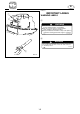
E ADJUSTING TRIM ANGLE EMU00951 q 404032* Manual tilt model There are 4 or 5 holes provided in the clamp bracket to adjust the outboard motor trim angle. 1) Stop the engine. 2) Remove the trim angle adjusting rod 1 from the clamp bracket while tilting the motor up slightly. 3) Reposition the rod in the desired hole. To raise the bow (“trim-out”), move the rod away from the transom. To lower the bow (“trim-in”), move the rod toward the transom.
E EMU19160 q 001672 w Trim angle settings and boat handling When the boat is on plane, a bow-up attitude results in less drag, greater stability and efficiency. This is generally when the keel line of the boat is up about 3 to 5 degrees. With the bow up, the boat may have a greater tendency to steer to one side or the other. Compensate for this as you steer. The trim tab can also be adjusted to help offset this effect.
E NOTE: Depending on the type of boat, the outboard motor trim angle may have little effect on the trim of the boat when operating. EMG70011 CRUISING IN SHALLOW WATER The outboard motor can be tilted up partially to allow operation in shallow water. w 8 Place the gear shift in the Neutral position before using the shallow water cruising system. 8 Run the boat at the lowest possible speed when using the shallow water cruising system.
E EMG71110 PROCEDURE N 1) Place the gear shift lever in Neutral. 2) Slightly tilt up the engine. Pull up the shallow water lever. 3) The shallow water lever will lock, supporting the engine in a partially raised position. When lowering the engine, slightly tilt up the engine and push the shallow water lever down. Then, slowly lower the engine to the normal position.
E EMH10110 TILTING UP/DOWN 105031 If the engine will be stopped for some time, or if the boat is moored in shallows, the engine should be tilted up to protect the propeller and casing from damage by collision with obstructions, and also to reduce salt corrosion. cC 8 Before tilting the motor, follow the procedures under “STOPPING ENGINE”. Never tilt the motor while the engine is running. Severe damage from overheating can result.
E EMU00288 PROCEDURE FOR TILTING UP N 1) Place the gear shift lever in Neutral. 2) Remove the fuel line connection from the motor. Hold the rear of the top cowling with one hand and fully tilt the engine up. 310012 3) 304014* 4) Push the tilt support knob into the clamp bracket. PROCEDURE FOR TILTING DOWN 1) 2) 3) 3-22 Slightly tilt up the engine. Pull out the tilt support knob. Tilt down the engine slowly to its home position.
E EMH60010 CRUISING IN OTHER CONDITIONS CRUISING IN SALT WATER After operating in salt water, wash out the cooling-water passages with fresh water to prevent them from becoming cloggedup with salt deposits. NOTE: Refer to cooling system flushing instructions in “TRANSPORTING AND STORING OUTBOARD MOTOR”. CRUISING IN TURBID WATER It is strongly recommended that the optional chromium-plated water-pump kit be installed if the outboard is to be used in turbid (muddy) water conditions.
E EMK00010 Chapter 4 MAINTENANCE SPECIFICATIONS .....................................4-1 TRANSPORTING AND STORING OUTBOARD MOTOR ...............................4-2 Trailering outboard motor ...................4-2 Storing outboard motor .......................4-3 PERIODIC MAINTENANCE......................4-6 Replacement parts ................................4-6 Maintenance chart ................................4-7 Cleaning and adjusting spark plug .....4-8 Checking fuel system .........................
E EMU01693*¯ SPECIFICATIONS Model Unit Item 8MH DIMENSIONS Overall length Overall width Overall height Transom height Weight S S S mm (in.) mm (in.) mm (in.) mm (in.) kg (lb.) 802 (31.6) 343 (13.5) 977 (38.5) 436 (17.2) 27 (59.4) PERFORMANCE Full throttle operating range Maximum output Idling speed (in neutral) r/min kW (HP) @ r/min r/min 4,500–5,500 5.
E EMU01369 TRANSPORTING AND STORING OUTBOARD MOTOR w Leaking fuel is a fire hazard. When transporting and storing the outboard motor, close the air vent screw and fuel cock to prevent fuel from leaking. EMU00326 TRAILERING OUTBOARD MOTOR q The motor should be trailered and stored in the normal running position. If there is insufficient road clearance in this position, then trailer the motor in the tilt position using a motor support device such as a transom saver bar.
E EMU00327 Clamp handle mounting model When transporting or storing the outboard motor while removed from a boat, fold the tiller handle and lean the motor on the tiller handle to keep in a horizontal position. 102013 cC Keep the power unit higher than the propeller at all times. Otherwise, cooling water can run into the cylinder, which could result in damage. NOTE: Place a towel or the like under the outboard motor to protect it from damage.
E EMU00338 Flushing Cooling System and Fogging Engine Cooling system flushing is essential to prevent the cooling system from clogging up with salt, sand, or dirt. In addition, fogging of the engine is mandatory to prevent expensive engine damage due to rust. Perform the flushing and fogging at the same time. w 8 Do not touch or remove electrical parts when starting or during operation. 8 Keep hands, hair and clothes away from flywheel and other rotating parts while engine is running.
E EMK26010 Lubrication 1) Remove the spark plugs, and spray a 10 second spray of Yamaha Stor-Rite Engine Fogging Oil into each cylinder. Grease the spark plug threads and reinstall the spark plugs and torque to proper specification. (Refer to the Periodic Maintenance section, “Cleanning and adjusting spark plug.”). 2) Turn the engine over with the stop lanyard disconnected to work the fogging oil into the piston rings. 3) Change the lower unit oil.
E EMU01569 PERIODIC MAINTENANCE w Be sure to turn off the engine when you perform maintenance unless otherwise specified. If the owner is not familiar with machine servicing, this work should be done by a Yamaha dealer or other qualified mechanic. Maintenance, replacement, or repair of the emission control devices and systems may be performed by any marine engine repair establishment or individual.
E EMU19270 MAINTENANCE CHART Frequency of maintenance operations may be adjusted according to the operating conditions, but the following table gives general guidelines. Refer to the sections in this chapter for explanations of each owner-specific action. The mark (●) indicates the check-ups which you may carry out yourself. The mark (1) indicates work to be carried out by your Yamaha dealer.
E EMU01202 CLEANING AND ADJUSTING SPARK PLUG w When removing or installing a spark plug, be careful not to damage the insulator. A damaged insulator could allow external sparks, which could lead to explosion or fire. The spark plug is an important engine component and is easy to inspect. The condition of the spark plug can indicate something about the condition of the engine.
E When fitting the plug, always clean the gasket surface and use a new gasket. Wipe off any dirt from the threads and screw in the spark plug to the correct torque. Spark plug torque: Refer to “SPECIFICATIONS”, page 4-1. NOTE: If a torque-wrench is not available when you are fitting a spark plug, a good estimate of the correct torque is 1/4 to 1/2 a turn past finger-tight. Have the spark plug adjusted to the correct torque as soon as possible with a torque-wrench. Initial of spark plug I.D.
E EMK38010 CHECKING FUEL SYSTEM w Gasoline (petrol) and its vapors are highly flammable and explosive. Keep away from sparks, cigarettes, flames or other sources of ignition. Check the fuel line for leaks, cracks, or malfunctions. If any problem is found, it should be repaired immediately by Yamaha dealer or other qualified mechanic. Checking points 8 Fuel system parts leakage. 8 Fuel hose joint leakage. 8 Fuel hose cracks or other damage. 8 Fuel connector leakage.
E EMM52010 INSPECTING AND REPLACING FUEL FILTER w Gasoline (petrol) is highly flammable, and its vapors are flammable and explosive. 8 If you have any question about properly doing the procedure, consult your Yamaha dealer. 8 Do not perform the procedure on a hot or running engine. Allow the engine to cool. 8 There will be fuel in the fuel filter. Keep away from sparks, cigarettes, flames or other sources of ignition. 8 The procedure will allow some fuel to spill. Catch fuel in a rag.
E EMU09912 INSPECTING IDLING SPEED w 8 Do not touch or remove electrical parts when starting or during operation. 8 Keep hands, hair and clothes away from flywheel and other rotating parts while engine is running. cC This procedure must be performed while the outboard motor is in the water. A flushing attachment or test tank can also be used. A diagnostic tachometer should be used for this procedure.
E EMK78010 CHECKING WIRING AND CONNECTORS 1) 2) Check that each grounding wire is properly secured. Check that each connector is engaged securely. 606011 EXHAUST LEAKAGE Start the engine and check that no exhaust leaks from the joints between the exhaust cover, cylinder head and crank case. WATER LEAKAGE Start the engine and check that no water leaks from the joints between the exhaust cover, cylinder head and crank case.
E EMU00366 GREASING Yamaha marine grease (Water resistant grease) 103101 4-14
E EMU00388 CHECKING PROPELLER w 210012 602051 You could be seriously injured if the engine accidentally starts while you are near the propeller. 8 Before inspecting, removing or installing the propeller, remove the spark plug caps from the spark plugs. Also, put the shift control in Neutral, put the main switch in the “OFF” position and remove the key, and remove the lanyard from the engine stop switch. Turn off the battery cut-off switch if your boat has one.
E EMU00977 Removing the Propeller 1) Straighten the cotter-pin 1 and pull it out using a pair of pliers. 602052 2) q 3) e t w r 000607 4-16 Remove the propeller nut 2 and washer 3. Remove the propeller 4 and thrust washer 5.
E EMU00396 Installing the Propeller cC 8 Be sure to install the thrust washer before installing the propeller, otherwise the lower case and propeller boss may be damaged. 8 Be sure to use a new cotter pin and bend the ends over securely. Otherwise the propeller could come off during operation and be lost. 1) 2) 3) Apply Yamaha Marine grease or a corrosion resistant grease to the propeller-shaft. Install the thrust washer and propeller on the propeller-shaft.
E EMU01460¯ CHANGING GEAR OIL w 8 Be sure the outboard is securely fastened to the transom or a stable stand. You could be severely injured if the outboard falls on you. 8 Never get under the lower unit while it is tilted, even when the tilt-support lever/knob is locked. Severe injury could occur if the outboard accidentally falls. 1) 2) Tilt the outboard motor so that the oil drain plug is at the lowest point possible. Place a suitable container under the gear-case.
E 5) With the outboard motor in a vertical position, and using a flexible or pressurized filling device, inject the gear oil into the oil drain plug hole. Gear oil grade/capacity: Refer to “SPECIFICATIONS,” page 4-1. 601011 6) 7) When the oil begins to flow out of the oil level plug hole, insert and tighten the oil level plug. Insert and tighten the oil drain plug. EML22010 CLEANING FUEL TANK w Gasoline (petrol) is highly flammable, and its vapors are flammable and explosive.
E To clean the fuel tank: 1) Empty the fuel tank into an approved gasoline container. 2) Pour a small amount of suitable solvent in the tank. Reinstall the cap and shake the tank. Drain the solvent completely. 902066 To clean the fuel filter: 1) Remove the screws holding the fuel meter assembly. Pull the assembly out of the tank. 2) Clean the filter (located on the end of the suction pipe) in a suitable cleaning solvent. Allow the filter to dry. 3) Replace the gasket with a new one.
E EML40010 CHECKING BOLTS AND NUTS 1) 2) Check that bolts securing the cylinder head and engine and the nut securing the flywheel are tightened with their specified tightening torques. Check the tightening torques of other bolts and nuts. EMU00409 MOTOR EXTERIOR EMU00410 Cleaning the Outboard Motor After use, wash the exterior of the outboard with fresh water. Flush the cooling system with fresh water. NOTE: Refer to Flushing Cooling System instructions in “TRANSPORTING AND STORING OUTBOARD MOTOR”.
E EMN00010 Chapter 5 TROUBLE RECOVERY TROUBLESHOOTING ..............................5-1 TEMPORARY ACTION IN EMERGENCY ............................................5-5 Impact damege .....................................5-5 Starter will not operate.........................5-6 Treatment of submerged motor..........
E EMU01663¯ TROUBLESHOOTING A problem in the fuel, compression, or ignition systems can cause poor starting, loss of power, or other problems. The troubleshooting chart describes basic checks and possible remedies. (This chart covers all Yamaha outboard motors. Therefore, some items may not apply to your model.) If your outboard motor requires repair, bring it to a Yamaha dealer. If the engine warning indicator is flashing, consult your Yamaha dealer. Trouble A. Starter will not operate. B.
E Trouble Possible Cause 1. Spark plug(s) fouled or incorrect type. 2. Fuel system obstructed. 3. Fuel contaminated or stale. 4. Fuel filter clogged. 5. Failed ignition parts. 6. Spark plug gap incorrect. 7. Poor connections or damaged ignition wiring. C. Engine idles irregularly or stalls. 8. Specified engine oil not used. 9. Thermostat faulty or clogged. 10. Carburetor adjustments incorrect. 11. Fuel pump damaged. 12. Air vent screw on the fuel tank closed. 13. Choke knob pulled out. 14.
E Trouble Possible Cause 1. Propeller damaged. 2. Propeller pitch or diameter incorrect. 3. Trim angle incorrect. 4. Motor mounted at incorrect height on transom. 5. Boat bottom fouled with marine growth. 6. Spark plug(s) fouled or incorrect type. 7. Weeds or other foreign matter tangled on gear housing. 8. Fuel system obstructed. D. Engine power loss. 9. 10. 11. 12. Fuel filter clogged. Fuel contaminated or stale. Spark plug gap incorrect. Poor connections or damaged ignition wiring. 13.
E Trouble Possible Cause 1. Propeller damaged. 2. Propeller shaft damaged. E. Engine vibrates excessively. 3. Weeds or other foreign matter tangled on propeller. 4. Motor mounting bolt loose. 5. Steering pivot loose or damaged. 5-4 Remedy 1. Have propeller repaired or replaced. 2. Have serviced by a Yamaha dealer. 3. Remove and clean propeller. 4. Tighten bolt. 5. Tighten or have serviced by a Yamaha dealer.
E EMN20010 TEMPORARY ACTION IN EMERGENCY EMH80010 IMPACT DAMAGE w The outboard motor can be seriously damaged by a collision while operating or trailering. Damage could make the outboard motor unsafe to operate. 607011 If the outboard motor hits any object in the water, follow the procedure below; 1) Stop the engine immediately. 2) Inspect control system and all components for damage. Also, inspect the boat damage.
E EMN30110 STARTER WILL NOT OPERATE If the starter mechanism does not operate (engine cannot be cranked with the starter), the engine can be started with an emergency starter rope. w 8 Use this procedure only in an emergency and only to return to port for repairs. 8 When the emergency starter rope is used to start the engine, the start-ingear protection device does not operate. Make sure the transmission is in neutral.
E Procedure 1) Remove the top cowling. 2) Remove the starter/flywheel cover by removing the bolts. 208012 NOTE: On a model equipped with the start-ingear protection device (cable), disconnect the cable from the starter. 3) Prepare the engine for starting. See "STARTING ENGINE" for procedures. Be sure the engine is in Neutral and that the lanyard is attached to the engine stop switch. On the electric start model the main switch must be on if the main switch is equipped.
E EMN50011 TREATMENT OF SUBMERGED MOTOR 107012 If the outboard motor is submerged, immediately take it a Yamaha dealer. Otherwise, some corrosion may begin almost immediately. If you cannot immediately take the outboard motor to a Yamaha dealer, follow the procedure bellow for taking care to minimize engine damage. 1) 2) 107013 3) 4) 5) Thoroughly wash away mud, salt, seaweed, etc. with fresh water.
E -MEMO-
E EMP00010 Chapter 6 INDEX INDEX........................................................
E EMP10010 INDEX A Adjusting trim angle..............................3-17 Air vent screw...........................................2-2 B Basic Boating rules (Rules of the road) ...................................1-6 Break in (running in) engine ...................3-8 C Changing gear oil...................................4-18 Checking bolts and nuts........................4-21 Checking fuel system ............................4-10 Checking painted surface of motor......4-21 Checking propeller................
E Start-in-gear protection.........................1-13 Starter will not operate............................5-6 Starting engine.......................................3-10 Steering friction adjustment ...................2-6 Stopping engine.....................................3-15 Storing outboard motor ..........................4-3 T Temporary action in emergency............5-5 Throttle control grip.................................2-4 Throttle friction adjustment ....................2-5 Throttle indicator ..
EMU01599 IMPORTANT WARRANTY INFORMATION FOR U.S.A. AND CANADA Welcome to the Yamaha Family! Congratulations on the purchase of your new Yamaha marine power. Yamaha is committed to exceptional customer satisfaction, and we want your ownership experience to be a satisfying one. Please read the following warranty information to help ensure satisfaction with your Yamaha. Yamaha is ready to stand behind your purchase with strong warranty coverage.
5. Your warranty applies specifically to repairs made in the country of purchase. If your U.S.-purchased Yamaha needs warranty service while in Canada, or your Canadian purchased Yamaha needs service while in the United States, Yamaha will assist the local dealer whenever possible. However, some products available in one country may not be sold or serviced in the other. 6.
EMU00912* YAMAHA MOTOR CORPORATION, U.S.A. OUTBOARD MOTOR TWO YEAR LIMITED WARRANTY Yamaha Motor Corporation, U.S.A. is proud of its heritage and reputation for producing products with high standards of quality and workmanship. Product excellence provides the cornerstone for our commitment to customer satisfaction. The Yamaha Outboard Limited Warranty is your assurance of this commitment.
SPECIFIC PARTS EXCLUDED FROM WARRANTY. Parts replaced due to normal wear or routine maintenance such as oil, spark plugs, shear pins, propellers, hubs, fuel and oil filters, brushes for the starter motor and power tilt motor, water pump impellers, and anodes, are not covered by warranty. Charges for removal of the motor from a boat and transporting the motor to and from an authorized Yamaha Outboard Motor Dealer are excluded from warranty coverage.
CUSTOMER SERVICE If your machine requires warranty service, you must take it to any authorized Yamaha outboard dealer within the continental United States. Be sure to bring your warranty registration identification or other valid proof of the original date of purchase. If a question or problem arises regarding warranty, first contact the owner of the dealership. Since all warranty matters are handled at the dealer level, this person is in the best position to help you.
EMU01178 IMPORTANT WARRANTY INFORMATION IF YOU USE YOUR YAMAHA OUTSIDE U.S.A. OR CANADA Welcome to the Yamaha Family! Congratulations on the purchase of your new Yamaha marine power. Yamaha is committed to exceptional customer satisfaction, and we want your ownership experience to be a satisfying one. Please read the following warranty information to help ensure satisfaction with your Yamaha. This model was manufactured as a U.S.A.
Printed in France January 2003-0.
Warranty card 12/6/01 7:40 PM Page 1
Warranty card 12/6/01 7:40 PM Page 2