DSP-A592 DSP-A492 Natural Sound AV Amplifier Amplificateur audiovisuel “Son Naturel” Natural Sound AV-Verstärker Natural Sound AV-förstärkare Amplificatore AV a suono naturale Amplificador AV de Sonido Natural Natural Sound AV Versterker OWNER’S MANUAL MODE D’EMPLOI BEDIENUNGSANLEITUNG BRUKSANVISNING MANUALE DI ISTRUZIONI MANUAL DE INSTRUCCIONES GEBRUIKSAANWIJZING
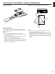
SUPPLIED ACCESSORIES ACCESSOIRES FOURNIS MITGELIEFERTE ZUBEHORTEILE MEDFOLJANDE TILLBEHOR ACCESSORI IN DOTAZIONE ACCESORIOS INCLUIDOS BIJGELEVERDE ACCESSOIRES ● ● ● ● ● ● ● After unpacking, check that the following parts are included. Après le déballage, vérifier que les pièces suivantes sont incluses. Nach dem Auspacken überprüfen, ob die folgenden Teile vorhanden sind. Kontrollera efter det apparaten packats upp att följande delar finns med.
FEATURES ● 5 Speaker Configuration DSP-A592 ● Test Tone Generator for Easier Speaker Balance Adjustment 70W + 70W (8Ω) RMS Output Power, 0.04% THD, 20–20,000 Hz Center: 70W (8Ω) RMS Output Power, 0.07% THD, 1 kHz Rear: 35W + 35W (8Ω) RMS Output Power, 0.3% THD, 1 kHz DSP-A492 ● 3 Center Channel Modes (NORMAL/WIDE/PHANTOM) Main: DSP-A592 only Main: 65W + 65W (8Ω) RMS Output Power, 0.04% THD, 20–20,000 Hz Center: 65W (8Ω) RMS Output Power, 0.09% THD, 1 kHz Rear: 20W + 20W (8Ω) RMS Output Power, 0.
CAUTION : READ THIS BEFORE OPERATING YOUR UNIT. 1. To assure the finest performance, please read this manual carefully. Keep it in a safe place for future reference. 2. Install this unit in a cool, dry, clean place – away from windows, heat sources, sources of excessive vibration, dust, moisture and cold. Avoid sources of humming (transformers, motors). To prevent fire or electrical shock, do not expose the unit to rain or water. 3. Never open the cabinet.
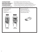
Battery installation Remote control transmitter operation range English NOTES ABOUT THE REMOTE CONTROL TRANSMITTER l6 20 l2 28 8 4 40 2 60 0 –dB 2 Remote control sensor 1 3 Within approximately 6 m (19.7 feet) 30° 30° Battery replacement If you find that the remote control transmitter must be used closer to the main unit, the batteries are weak. Replace both batteries with new ones. Notes ● Use only AA, R6, UM-3 batteries for replacement. ● Be sure the polarities are correct.
PROFILE OF THIS UNIT You are the proud owner of a Yamaha stereo receiver –an extremely sophisticated audio component. The Digital Sound Field Processor (DSP) built into this unit takes advantage of Yamaha’s undisputed leadership in the field of digital audio processing to bring you a whole new world of listening experiences.
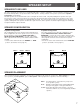
English SPEAKER SETUP SPEAKERS TO BE USED This unit is designed to provide the best sound-field quality with a 5 speaker configuration. The most effective speakers to use with this unit are main speakers, rear speakers and a center speaker. You may omit the center speaker. (Refer to the “4-Speaker Configuration” shown below.) The main speakers are used for the main source sound plus the effect sounds. They will probably be the speakers from your present stereo system.
CONNECTIONS Never plug in this unit and other components until all connections are completed. CONNECTIONS WITH OTHER COMPONENTS When making connections between this unit and other components, be sure all connections are made correctly, that is to say L (left) to L, R (right) to R, “+” to “+” and “–” to “–”. Also, refer to the owner’s manual for each component to be connected to this unit. * If you have YAMAHA components numbered as 1, 2, 3, etc.
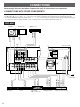
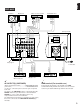
English DSP-A492 TV/Satellite tuner VIDEO OUT AUDIO IN VIDEO IN AUDIO OUT VIDEO OUT VIDEO IN GND OUTPUT Video cassette recorder AUDIO OUT Monitor TV Turntable 2 * (Europe model) IMPEDANCE SELECTOR REAR 6ΩMIN./SPEAKER OUTPUT GND CENTER VIDEO SIGNAL MAIN REAR MONITOR OUT DVD/LD IN VCR OUT TV/DBS DUAL A OR B:4ΩMIN./SPEAKER A B:8ΩMIN./SPEAKER CENTER REAR 8ΩMIN./SPEAKER CENTER SINGLE:8ΩMIN./SPEAKER DUAL:4ΩMIN./SPEAKER MAIN A OR B:8ΩMIN./SPEAKER A B:I6ΩMIN.
DSP-A592 only CONNECTING TO VIDEO AUX TERMINALS (ON THE FRONT PANEL) These terminals are used to connect any video input source such as a camcorder to this unit. VIDEO AUX S VIDEO VIDEO L AUDIO R AUDIO OUT R R AUDIO OUT L L VIDEO OUT VIDEO Camcorder S VIDEO OUT S VIDEO DSP-A592 only CONNECTING TO S VIDEO TERMINALS If you have a video cassette recorder and a monitor equipped with “S” (high-resolution) video terminals, those terminals can be connected to this unit’s S VIDEO terminals.
English DSP-A592 only Connecting with a Dolby Digital (AC-3) Decoder If you have a Dolby Digital (AC-3) Decoder unit or an LD player etc. which incorporates a Dolby Digital (AC-3) Decoder, its discrete outputs can be connected to this unit.
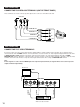
CONNECTING SPEAKERS Rear speaker DSP-A592 Rear speaker Subwoofer system Left Right Center speaker (Europe model) MAIN CENTER REAR (SURROUND) IMPEDANCE SELECTOR REAR (SURROUND) REAR 6ΩMIN./SPEAKER CENTER SINGLE:6ΩMIN./SPEAKER DUAL:3ΩMIN./SPEAKER MAIN A OR B:4ΩMIN./SPEAKER A B:8ΩMIN./SPEAKER CENTER C REAR 8ΩMIN./SPEAKER CENTER SINGLE:8ΩMIN./SPEAKER DUAL:4ΩMIN./SPEAKER MAIN A OR B:8ΩMIN./SPEAKER A B:I6ΩMIN.
Note on main speaker connections: One or two speaker systems can be connected to this unit. If you use only one speaker system, connect it to either the SPEAKERS A or B terminals. Note on a subwoofer connection: You may wish to add a subwoofer to reinforce low frequencies. Connect the SUBWOOFER OUTPUT terminal of this unit to the INPUT terminal of the subwoofer amplifier, and connect the speaker terminals of the subwoofer amplifier to the subwoofer.
OUTPUT terminals (for driving speakers with external amplifiers) DSP-A592 DSP-A492 REAR (SURROUND) OUTPUT terminals DSP-A592 only MAIN CENTER REAR (SURROUND) OUTPUT CENTER SUB WOOFER SUB WOOFER OUTPUT MAIN OUTPUT terminals These terminals are for rear channel line output. There is no connection to these terminals when you use the built-in amplifier.
English CONTROLS AND THEIR FUNCTIONS FRONT PANEL DSP-A592 1 2 3 NATURAL SOUND 4 AV AMPLIFIER 5 6 7 CINEMA DSP DSP–A592 VOLUME l6 VCR PRESET SLEEP ms dB STEREO POWER kHz MHz MEMORY AUTO PTY HOLD INFO AFFAIRS SPORT PTY RT CT EON NEWS PS 0 20 40 60 l00 PRO LOGIC ENHANCED 20 DVD/LD l2 28 8 60 2 NORMAL WIDE PHANTOM EFFECT OFF VIDEO AUX TAPE (MD) MON 4 40 2CH/6CH TAPE MONITOR PRO LOGIC CONCERT MONO DISCO ROCK CONCERT VIDEO MOVIE STADIUM CONCERT HALL ENHANCED TUNER EFFECT
1 POWER switch 0 EFFECT button Press this switch to switch the power on. Press it again to switch the power off. Switches on/off the digital sound field processor (including the Dolby Pro Logic Surround decoder). 2 Standby mode indicator While the power is on, pressing the POWER key on the remote control transmitter switches the unit to the standby mode. In this mode, this indicator is illuminated. A BASS EXTENSION switch 3 Remote control sensor Receives signals from the remote control transmitter.
English DISPLAY PANEL DSP-A592 1 2 SLEEP ms dB 3 4 NORMAL WIDE PHANTOM EFFECT OFF TAPE MONITOR PRO LOGIC CONCERT MONO DISCO ENHANCED ROCK CONCERT VIDEO MOVIE STADIUM CONCERT HALL 5 DSP-A492 6 1 2 SLEEP NORM WIDE PHANTOM EFFECT OFF PRO LOGIC CONCERT MONO DISCO ROCK CONCERT ENHANCED VIDEO MOVIE STADIUM CONCERT HALL ms dB TAPE MON 5 1 Multi-information display Displays various information, for example name of selected DSP program and name of selected input source.
REMOTE CONTROL TRANSMITTER The remote control transmitter provided with this unit is designed to control all the most commonly used functions of this unit. If the CD player, tuner and tape deck connected to this unit are YAMAHA components designed for remote control compatibility, then this remote control transmitter will also control various functions of each component.
8 EFFECT ON/OFF key 1 DELAY/CENTER/REAR/SWFR and TIME/LEVEL +/– Switches on/off the digital sound field processor (including the Dolby Pro Logic Surround decoder). keys DSP-A592 Adjust the delay time (DELAY), the rear channel output level (REAR), center channel output level (CENTER) and the output level to the SUBWOOFER OUTPUT terminal (SWFR). Select the item which you want to adjust by pressing the DELAY/CENTER/REAR/SWFR key and adjust its time or level by pressing the TIME/LEVEL +/– key.
SPEAKER BALANCE ADJUSTMENT This procedure lets you adjust the sound output level balance between the main, center, and rear speakers using the built-in test tone generator. When this adjustment is performed, the sound output level heard at the listening position will be the same from each speaker. This is important for the best performance of the digital sound field processor and the Dolby Pro Logic Surround decoder.
TIME/ LEVEL – + PROGRAM V–AUX DIR A l6 20 DSP-A492 DELAY/CENTER /REAR/SWFR TEST TV/DBS DIR B REC/PAUSE ON/OFF + PROGRAM DELAY/CENTER TEST /REAR PROLOGIC ENHANCED DVD/LD 2CH/6CH VCR PLAY l2 28 TIME/ LEVEL – EFFECT PROLOGIC ENHANCED VCR DIR A DIR B REC/PAUSE – + A/B 4 PLAY TAPE – 0 PRESET + A/B/C/D/E A/B TUNER –dB DISC PLAY PRESET CD A/B/C/D/E PLAY DISC PHONO TAPE POWER TUNER CD PHONO VOLUME POWER SLEEP VOLUME SLEEP 6 7 Select the center channel out
DSP-A592 TIME/ LEVEL – + PROGRAM 9 V–AUX DIR A TV/DBS DIR B REC/PAUSE + DISC ON/OFF 9 PLAY PLAY 10 + PROGRAM DVD/LD 2CH/6CH A/B/C/D/E TIME/ LEVEL – EFFECT PROLOGIC ENHANCED VCR PRESET 10 DELAY/CENTER /REAR/SWFR TEST A/B – DSP-A492 DELAY/CENTER TEST /REAR PROLOGIC ENHANCED VCR DIR A DIR B REC/PAUSE – + TAPE PRESET CD PLAY A/B/C/D/E DISC PLAY PHONO POWER a) b) VOLUME 22 CD POWER VOLUME SLEEP Adjust the sound output levels of the center speaker and the rea
English BASIC OPERATIONS TO PLAY A SOURCE 3 2 1, 6 l6 20 l2 28 8 4 40 2 60 0 –dB 4 : Provided for DSP-A592 only. 1 7 4 VOLUME Select the main speakers to be used. l6 20 l2 SPEAKERS 28 8 A B 4 40 ON OFF 2 60 0 –dB Set to the “∞” position. 2 Turn the power on. * 5 6 POWER If you use two main speaker systems, press both the A and B switches. Play the source. VOLUME l6 20 l2 28 3 Select the desired input source by using the input selector buttons.
Notes on using the input selector buttons DSP-A592 ● Note that pressing on each input selector button selects the source which is connected to the corresponding input terminals on the rear panel. * To select the source connected to the VIDEO AUX terminals on the front panel, press VIDEO AUX. ● The selection of TAPE (MD) MON cannot be canceled by pressing another input selector button. To cancel it, press TAPE (MD) MON again so that “TAPE MONITOR” disappears from the display.
English TO RECORD A SOURCE TO TAPE (OR MD) 1 4 2 l6 20 l2 28 8 4 40 2 60 0 –dB 1 Notes DSP-A592 Select the source to be recorded. The settings of DSP and the VOLUME, BASS, TREBLE, BALANCE controls and the BASS EXTENSION switch have no effect on the material being recorded. ● In step 1, do not make an input source selection so that “6ch” appears on the display. Signals input to this unit’s 6CH DISCRETE INPUT DVD/LD TV/DBS terminals cannot be recorded by a tape deck, MD recorder or VCR.
Selecting the SPEAKER system Because one or two speaker systems (as main speakers) can be connected to this unit, the SPEAKERS switches allow you to select speaker system A or B, or both at once.
This unit incorporates a sophisticated, multi-program digital sound field processor. The processor allows you to electronically expand and change the shape of the audio sound field from both audio and video sources, creating a theater-like experience in your listening room. You can create an excellent audio sound field by selecting a suitable sound field program (this will, of course, depend on what you will be listening to), and adding desired adjustments.
To play a source with the digital sound field processor DSP-A592 TIME/ LEVEL – l6 20 28 + PROGRAM l2 DELAY/CENTER /REAR/SWFR TEST V–AUX 4 DIR A 0 –dB VCR TV/DBS – DIR B REC/PAUSE PRESET + 2 PROLOGIC ENHANCED POWER CONCERT VIDEO EFFECT ON/OFF 2 TV/DBS DVD/LD DIR B REC/PAUSE – + PLAY A/B TUNER PLAY DIR A TAPE PRESET CD A/B/C/D/E DISC PLAY CD VOLUME POWER VOLUME SLEEP ● When a monaural sound source is played with DOLBY PRO LOGIC or DOLBY PRO LOGIC ENHANCED, no sound
English Adjustment of the CENTER LEVEL If desired, you can adjust the sound output level of the center speaker even if the output level is already set in “SPEAKER BALANCE ADJUSTMENT” on page 22. 1 Notes ● This adjustment can be made only when the digital sound field program DOLBY PRO LOGIC or DOLBY PRO LOGIC ENHANCED is selected, or the “6CH” input source mode is selected. Press once or more so that “CENTER” appears on the display.
Adjustment of DELAY TIME You can adjust the time difference between the beginning of the sound from the main speakers and the beginning of the effect sound from the rear speakers. The larger the value, the later the effect sound is generated. This adjustment can be made to all programs individually.
English SETTING THE SLEEP TIMER If you use the SLEEP timer of this unit, you can make this unit turn off automatically. When you are going to sleep while enjoying a broadcast or other desired input source, this timer function is helpful. Notes ● The SLEEP timer can be controlled only with the remote control transmitter. ● The components on which the SLEEP timer is effective are the sources connected to the SWITCHED AC OUTLET(S) on the rear panel of this unit.
TROUBLESHOOTING If the unit fails to operate normally, check the following points to determine whether the fault can be corrected by the simple measures suggested. If it cannot be corrected, or if the fault is not listed in the SYMPTOM column, disconnect the power cord and contact your authorized YAMAHA dealer or service center for help. SYMPTOM Firmly plug in the power cord. The IMPEDANCE SELECTOR switch on the rear panel is not set to the upper or the lower end exactly.
AUDIO SECTION Minimum RMS Output Power per Channel Main L, R 8 ohms, 20 Hz to 20 kHz, 0.04% THD ............................70W+70W ............................65W+65W Center 8 ohms, 1 kHz, 0.07% THD..................70W 8 ohms, 1 kHz, 0.09% THD..................65W Rear 8 ohms, 1 kHz, 0.3% THD ..........35W+35W 8 ohms, 1 kHz, 0.7% THD ..........20W+20W Maximum Power [General model only] 8 ohms, 1 kHz, 10% THD Main L, R ............
YAMAHA YAMAHA YAMAHA YAMAHA YAMAHA YAMAHA YAMAHA ELECTRONICS CORPORATION, USA 6660 ORANGETHORPE AVE., BUENA PARK, CALIF. 90620, U.S.A. CANADA MUSIC LTD. 135 MILNER AVE., SCARBOROUGH, ONTARIO M1S 3R1, CANADA ELECTRONIK EUROPA G.m.b.H. SIEMENSSTR. 22-34, 25462 RELLINGEN BEI HAMBURG, F.R. OF GERMANY ELECTRONIQUE FRANCE S.A. RUE AMBROISE CROIZAT BP70 CROISSY-BEAUBOURG 77312 MARNE-LA-VALLEE CEDEX02, FRANCE ELECTRONICS (UK) LTD. YAMAHA HOUSE, 200 RICKMANSWORTH ROAD WATFORD, HERTS WD1 7JS, ENGLAND SCANDINAVIA A.