WaveRunner GP GP800Y OWNER’S/OPERATOR’S MANUAL READ THIS MANUAL CAREFULLY BEFORE OPERATION! U.S.A.Edition YAMAHA MOTOR CORPORATION, U.S.A.
E EJU00270 TO THE OWNER Thank you for choosing a Yamaha Water Vehicle. This Owner’s Manual contains information you will need for proper operation, maintenance, and care. A thorough understanding of these simple instructions will help you to obtain maximum enjoyment from your new Yamaha. If you have any questions about the operation or maintenance of your water vehicle, please consult a Yamaha dealer. YAMAHA MOTOR CO., LTD.
EJU00273 CONTENTS GENERAL AND SAFETY INFORMATION FEATURE AND FUNCTIONS OPERATION AND RIDING MAINTENANCE AND CARE TROUBLESHOOTING AND EMERGENCY PROCEDURE INDEX READ THIS OWNER’S / OPERATOR’S MANUAL CAREFULLY BEFORE OPERATING YOUR WATER VEHICLE.
E EJU00274 Chapter 1 GENERAL AND SAFETY INFORMATION IDENTIFICATION NUMBER RECORDS..................................................1-1 PRI-I.D. number ..................................1-1 Hull identification number (H.I.N) ....1-1 Engine number...................................1-1 EMISSION CONTROL INFORMATION...1-2 IMPORTANT LABELS ..............................1-3 Location...............................................1-3 Labels ..................................................1-4 SAFETY INFORMATION .
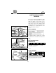
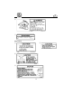
E EJU00699 IDENTIFICATION NUMBER RECORDS Record your Primary identification (PRIID) number, Hull identification number (HIN) and Engine serial number in the spaces provided, to assist you in ordering spare parts from your Yamaha water vehicle dealer. Also record and keep these ID numbers in a separate place in case your water vehicle is stolen. q EJU00281a PRI-I.D. NUMBER GU0-001 w The PRI-ID number is stamped on a label 1 attached to the deck under the rear seat.
E EJU00631a q EMISSION CONTROL INFORMATION w RU0625 This engine conforms to 2000 U.S. Environmental Protection Agency (EPA) regulation for marine SI engines. 8 Approval label of Emission control certificate This label is attached to the electrical box. 1 Emission control information label EMISSION CONTROL INFORMATION ENGINE FAMILY : THIS ENGINE CONFORMS TO 2000 U.S. EPA REGULATIONS FOR MARINE SI ENGINES.
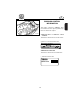
E EJU00293 IMPORTANT LABELS LOCATION w !2 q i !3 eo !4 !0 t r y RU061* u !5 !1 RU063 RU062 1-3
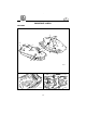
E LABELS Warning labels q w e GP8-U411A-00 r t WARNING Do not add gasoline to the oil tank. Fire or explosion could result.
E y u WARNING Do not touch or remove electrical parts when starting or running the engine.
E Other labels !2 F I R E E X T I N G U I S HE R C O M P A R T M EN T !3 RECOMMENDED OIL YAMALUBE 2-W or an equivalent TC-W3 certified outboard oil.
E A responsible adult must supervise operation of this vehicle by minors. Many states have minimum age and education requirements. Always check states and all applicable local boating laws that apply to you before you operate the water vehicle.
E EJU00613 CRUISING LIMITATIONS EJX24011 8 Do not jump boat wakes or follow another boat or watercraft too closely. You increase your risk of colliding with another boat, which could result in severe injury or death. Do not jump waves, wakes, or any objects. You risk severe impact injuries. Jumping can also cause damage to the water vehicle. 8 Never ride in water that is less than 60 cm ( 2 feet ) deep. You increase your chance of hitting an underwater obstacle. You could be injured.
E EJU00616a OPERATIONAL REQUIREMENTS EJX16010 8 Operating your water vehicle requires skills acquired only through practice over a period of time. Take the time to learn the basic operating techniques well, before attempting more difficult maneuvers. EJX11211 8 Both operator and a passenger must always wear a U.S. Coast Guard approved personal flotation device (vest-type) because of the drowning hazards associated with water sports.
E A helmet may have potential safety hazard, as well. A helmet could catch the water during a fall into the water. This is commonly called “bucketing”. The resulting strain on your neck could cause choking, severe and permanent neck injuries, or death. A helmet could also increase the risk of an accident if it reduces your vision or hearing, or if it distracts you or increases your fatigue.
E 8 To prevent accidental starting of the engine, always remove the lock plate from the engine stop lanyard switch when the engine is not running. e w q 8 This water vehicle is included in the Class A inboard boat classification of the U.S. Coast Guard. A water craft of this type MUST carry a fire extinguisher of a B-1 classification, with a capacity of two pounds or more when navigating in waters under Coast Guard jurisdiction.
E EJU00314a WATER VEHICLE CHARACTERISTICS K1053 8 Jet thrust turns the water vehicle. If you are going faster than trolling speeds (the lowest maneuvering speed), you must use throttle to turn. If you release the throttle completely, you cannot turn-even if you turn the handlebars. Practice turning in an open area without obstructions until you have a good feel for this maneuver. 8 Yamaha Water Vehicles are water-jet propelled. The jet pump is directly connected to the engine.
E EJU00319 STEERING AND SAILING RULES AND SOUND SIGNALS RULES OF THE ROAD Your Yamaha water vehicle is legally considered a power boat. Operation of the water vehicle must be in accordance with the rules and regulations governing the waterway on which it is used. Just as there are rules which apply when you are driving on streets and highways, there are waterway rules which apply when you are riding your water vehicle.
E In other words, follow the standard rules except when a collision will occur unless both vessels try to avoid each other. If that is the case, both vessels become “Give-Way” vessels.
E Overtaking If you are passing another vessel, you are the “Give-Way” vessel. This means that the other vessel is expected to maintain its course and speed. You must stay out of its way until you are clear of it. Likewise, if another vessel is passing you, you should maintain your speed and direction so that the other vessel can steer itself around you. Sailing Vessel Right-of-Way Sailing vessels should normally be given the right-of-way. The exceptions to this are: 1. 2. 3.
E Remember, markings may vary by geographic location. Always consult local boating authorities before riding your water vehicle in unfamiliar waters. tion. These markers are white with black letters and orange boarders. They signify speed zones, restricted areas, danger areas, and general information. N EL MAIN CHANNEL BUOYS A N " 6" A C H C " 1" M D N N N O A White Light EL C H A R Odd number. increasing toward head of navigation.Leave to port (left) proceeding upstream.
E EJU00320 EJU00322 TO GET MORE BOATING SAFETY INFORMATION ENJOY YOUR WATER VEHICLE RESPONSIBLY Be informed about boating safety. Additional publications and information can be obtained from many organizations, including the following. 8 You share the areas you enjoy when riding your Water Vehicle with others and with nature. So your enjoyment includes a responsibility to treat these other people, and the lands, waters, and wildlife with respect and courtesy.
E cC EJU00323a FUEL REQUIREMENTS Use only fresh gasoline (petrol) that has been stored in clean containers. GASOLINE(PETROL) w GASOLINE (PETROL) AND ITS VAPORS ARE HIGHLY FLAMMABLE AND EXPLOSIVE! 8 Do not smoke when refueling, and keep away from sparks, flames, or other sources of ignition. 8 Stop engine before refueling. 8 Refuel in a well-ventilated area. Do not stand or sit on the water vehicle while refueling in case of fire. 8 Take care not to spill gasoline (petrol).
E – MEMO –
EJU00326 Chapter 2 FEATURES AND FUNCTIONS LOCATION OF MAIN COMPONENTS.........................................2-1 OPERATION OF CONTROLS AND OTHER FUNCTIONS.......................2-4 Front seat ............................................2-4 Rear seat .............................................2-4 Front hood ..........................................2-5 Fuel tank filler cap ..............................2-6 Fuel cock .............................................2-6 Engine stop switch .....................
E EJU00327 EJD10010 LOCATION OF MAIN COMPONENTS o !0 !1 !2 i u u e r t y !8 !6 !7 !5 !4 !3 w q !9 1 Cooling water pilot outlets Check point of cooling water flowing. 2 Bow eye Rope attachment point for transporting, mooring, or towing the water vehicle in an emergency. 3 Front storage compartment 4 Fire extinguisher compartment 5 Front hood 6 Choke knob Pull knob when starting a cold engine. 7 Rope hole Rope attachment point for transporting, mooring.
E u i y t e r w q o TK002A 1 Engine stop switch lanyard (Cable) By connecting to the stop switch and operator will stop the engine if the operator falls off the vehicle. 2 Engine stop switch Depress to stop the engine. 3 Engine stop lanyard switch Removing the lock plate makes to stop the engine and disable to start the engine. 4 Lock plate Insert the lock plate in the engine stop lanyard switch to allow the engine to be started. Remove the plate to stop the engine or prevent it from starting.
E r q t !1 o e i w u y 1 Fuel tank 2 Water separator To trap water from the air passage to the fuel tank. 3 Fuel filter Prevents dust contained in fuel from getting into the engine. 4 Oil tank 5 Silencer To help prevent water from getting into the engine and reduce the air intake noise. !0 TK004A 6 High tension cord Deliver electrical current to the spark plug. 7 Spark plug/Spark plug cap 8 Electrical box Contains most electrical components, included fuse in this water resistant box.
E EJU00328 OPERATION OF CONTROLS AND OTHER FUNCTIONS EJU00334 FRONT SEAT q GP7-005 w There is a seat latch under the rear seat. First remove the rear seat to reach the front seat latch lever, then remove the front seat. Removal Pull the front seat latch lever up, then lift the rear of the seat , and pull back. 1 Front seat latch lever GU0-006 Installation Position the seat on the deck so the front projection of the seat fits under the stay on the deck.
E Installation Position the seat on the deck so the front projections on the underside of the seat fits into the stays on the deck. Then push the rear of the seat down until the seat lock latches. GP7-009 NOTE: Make sure the seat is firmly secured before riding. GP7-010 EJU00343a EJD15710 q FRONT HOOD The front food is secured by the latch 1. Pull up the latch lever and lift the food to open it. GP7-011 NOTE: Make sure the front food is firmly secured with the latch before riding.
E EJU00345 EJD18010 FUEL TANK FILLER CAP To remove the fuel tank filler cap, turn it counterclockwise. 1 Fuel tank filler cap q Be sure to tighten the cap securely before riding. GP7-013 EJU00704 FUEL COCK The fuel cock 1 supplies fuel from the fuel tank to the carburetor. The fuel cock has three positions; q GP7-014 OFF With the knob in this position, fuel does not flow. Always turn the knob to this position when the engine is not running.
E EJU00705 ENGINE STOP SWITCH The engine can be stopped normally by pressing the red button 1. q GP7-018 q EJU00706a e ENGINE STOP LANYARD SWITCH The engine can be also stopped if you fall off, or in case of an emergency, when the lock plate 1 attached to the lanyard 2 is pulled out from the engine stop lanyard switch 3. Should the lock plate be removed for any reason, the engine stops by itself.
E EJU00350a CHOKE KNOB Pulling this knob supplies a rich fuel-air mixture required to start a cold engine. NOTE: Refer to “STARTING THE ENGINE” in the chapter 3 for proper operation. q GP7-020 1 Choke knob EJU00351 THROTTLE LEVER Moving the throttle lever toward the handlebar increases engine speed. When the throttle lever is released, it returns to its closed (idle) position through the action of a return spring.
E EJU00354a COOLING WATER PILOT OUTLET GU0-023 This watercraft is equipped with a coolingwater pilot outlets at left side of the hull. Check that water comes out of the outlets while the engine is running. If you do not see any water at the outlets, cooling water may not be circulating in the engine. In that case, stop the engine and check for the cause (refer to overheat warning system).
E EJU00360 q w QUICK SHIFT TRIM SYSTEM (Q.S.T.S.) GP7-025 A B C D GP7-026 1 Trim shifting grip 2 Shift lock release lever D C B A D C N B A The trim angle of your water vehicle can be adjusted by operating the Q.S.T.S. Operating the trim shifting grip of the Q.S.T.S. changes the angle of the jet (output) nozzle at the rear of the craft.
E Shifting to “Bow Down” “Bow Down” puts more of the bow in the water. This gives the water vehicle more “hook”, which enhances turning performance. This position will also help the water vehicle get up on plane more quickly. At higher speeds, however, the water vehicle will have greater tendency to “bow steer” and follow waves and wakes in the water. Fuel economy and maximum speed are also reduced. Shifting to “Bow Up” “Bow Up” puts less of the bow in the water.
E w Before attempting to remove weeds or debris from the jet intake or impeller areas, shut off the engine and remove the lock plate from the engine stop lanyard switch. Severe injury or death could result from coming in contact with the rotating parts of the jet pump. GP7-029 cC If you cannot locate and correct the cause of the overheating, consult a Yamaha dealer. Continuing to operate at higher speeds could result in severe engine damage.
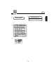
E EJU00656a MULTIFUNCTION METER WARNING 5 MODE 6 7 8 1000 r/min 4 3 2 1 A/ SET B C 0 mph GP7-032 WARNING 6 7 5 r MODE o 8 1000 r/min 4 3 2 1 mph 0 q !1 WARNING GP7-033 i B C y !0 !1 u w e 6 7 8 1000 r/min 4 3 2 1 A/ SET B C 0 “MODE” button “SET” button “CODE” setting buttons Tachometer Speedometer Fuel level meter Engine oil level meter Display for Clock, Hour meter, Trip meter and Trip timer 9 Warning lamp (LED) 0 Display for PADLOC and direction of warning indicator q
E EJU00657a PADLOC (Programmable digital locking ignition) This feature is provided to deter unauthorized use. The function allows you to chose either “START” or “LOCK” mode, as the situation requires, much as you would use a main switch key in a motor vehicle. If you have previously chosen “LOCK” mode, the engine will not start unless the right code is put in to select “START” mode. NOTE: If you do not use the PADLOC system, it is unnecessary to perform the initial setting of PADLOC.
E 4) WARNING A/ SET B C GP7-038 WARNING WARNING MODE MODE GP7-041* WARNING A/ SET B MODE C GP7-039* After completing code setting, the buzzer will sound 3 times and the display will show “SET”. Lastly, the display turns off and the warning lamp (LED) turns on again. After the meter has displayed this sequence, reconnect the blue connector. NOTE: 8 Your own code is kept even if the battery terminal is disconnected.
E 4) WARNING WARNING GP7-041 WARNING A/ SET If the code entered is correct, the mode will change from the previous mode to either “START” or “LOCK”. Then the mode display and buzzer will operate for 2 seconds. NOTE: 8 Once you select a mode, the mode will not be changed unless you perform this mode selection again. 8 If the wrong code has been put in, the mode display shows “ERROR” for 2 seconds and the buzzer will sound 5 times. Then the display turns back to “COdE”.
E EJU00384 Speedometer The meter shows the vehicle speed in miles per hour (mph). WARNING 5 MODE 6 7 8 1000 r/min 4 3 2 1 0 mph GP7-045 EJU00386a Fuel level meter The fuel level meter is provided for convenient fuel level checking while riding. The fuel level meter has four segments which show the amount of fuel remaining in the fuel tank. WARNING F4 F3 F2 F1 A/ SET B C Empty GP7-046 Display Capacity:L(US gal, Imp gal) F4 F3 F2 F1 ON more than 32 (8.5,7.0) F3 F2 F1 ON 26~32 (6.9,5.
E EJU00387a Engine oil level meter The engine oil level meter is provided for convenient oil level checking while riding. The engine oil level meter has three segments which show the amount of oil remaining in the oil tank. WARNING A/ SET B C F2 F1 Empty GP7-047 Display Capacity:L(US gal, Imp gal) F2 F1 ON more than 2.7 (0.71,0.59) F1 ON 1.2~2.7 (0.31,0.26)~(0.71,0.59) Empty ON 0~1.2 (0.31,0.26) NOTE: The indication of the segments differs on your operating condition.
E 6) The buzzer will sound twice. The warning indicator lamp and “SET” blinks for 2 seconds. Then the display turns to “CLOCK” and shows the time. NOTE: After the battery terminal is disconnected, the clock will be reset. EJU00390 Hour meter The hour meter is provided to make it easy to follow the maintenance schedule. The meter shows the hours of engine operation that have elapsed since the vehicle was new. To show the hour meter, press the “MODE” button until the display shows “HOUR.M”.
E EJU00660a WARNING A/ SET B C MODE GP7-053 WARNING A/ SET B C MODE GP7-054 Trip meter A trip meter is provided for measuring the approximate traveled distance in miles. To show the trip meter, press the “MODE” button until the display shows “TRIP”. After showing “TRIP”, the display turns to “MILE”. 1) When the display shows “MILE”, press the “MODE” button for at least 2 seconds. 2) The buzzer will sound twice. The warning lamp (LED) and “MILE” blinks for 2 seconds, and “000” is displayed.
E WARNING A/ SET B C GP7-056 8 Oil level If the oil remaining in the tank drops to about 1.2 L (0.31 US gal, 0.26 Imp gal) or the oil filter is clogged, the oil level segment, the oil warning indicator, “OIL” and the warning indicator lamp begin to blink. The buzzer also starts sounding. If the oil level warning indicator begins to blink, refill with engine oil as soon as possible. NOTE: If the warning indicator blinks with adequate oil in the tank, check the oil filter for clogging.
E EJU00909 STORAGE COMPARTMENTS The storage compartment(s) is provided to store the manuals, tools, and other equipment for cruising. Make sure all storage compartments are firmly secured before riding. NOTE: The storage compartment(s) is not designed to be waterproof. If you put the manuals in the compartment(s), store them in a waterproof bag to protect them from water damage. If your owner’s manual becomes damaged, order a replacement from a Yamaha water vehicle dealer.
E Grove compartment A grove compartment is provided below the handlebars. Push the latch button to open the lid. To close the lid, push the lid down to lock it securely. e r GP7-062 3 Latch button 4 Storage compartment: Capacity: 1 L (0.26 US gal, 0.22 Imp gal) Load limit: 1 kg (2.2 lb) Seat storage compartment A seat storage compartment is provided under the rear seat. Refer to “REAR SEAT” for removal and installation. GP7-063 5 Seat storage compartment Capacity: 21.2 L (5.6 US gal, 4.
E EJU00409 A B 1 GP7-065 YAMAHA ADJUSTABLE SPONSON (Y.A.S.) The sponsons have adjustable positioning to allow the operator to enhance either straight-line performance or turning performance according to the preference and operating conditions. 1 Sponson Adjusting to upward A There will be less water resistance in this position, so straight-ahead acceleration when on plane and top speed will be enhanced.
E – MEMO –
E EJU00410 Chapter 3 OPERATION AND RIDING GASOLINE (PETROL) AND ENGINE OIL FILLING...............................................3-1 Filling the Gasoline (petrol) tank ......3-1 Filling the oil tank...............................3-2 PRE-OPERATION CHECKS ......................3-3 Check list .............................................3-3 Check point .........................................3-4 OPERATION..............................................3-9 Break-in (Running-in) procedure......
E EJU00411 GASOLINE (PETROL) AND ENGINE OIL FILLING This engine uses Yamaha’s oil injection system, which provides superior lubrication by ensuring the proper oil ratio for all operating conditions. No fuel premixing is necessary (except during break-in / running-in). Simply pour gasoline (petrol) into the fuel tank and oil into the oil tank. EJU00414 FILLING THE GASOLINE (PETROL) TANK 1) 2) GP7-066 3) Remove the rear and front seats, so you can watch the fuel level.
E EJU00419 FILLING THE OIL TANK 1) 2) 3) Remove the rear and front seats, so you can watch the oil level. Open the oil tank filler cap, and very slowly add engine oil to the oil tank. Stop pouring when the oil just reaches the bottom of the filler tube. cC Do not allow the oil tank to empty completely. The oil injection pump must be bled to ensure proper oil flow after the tank empties. Otherwise, engine damage may occur.
E EJU00422 PRE-OPERATION CHECKS CHECK LIST Before operating this water vehicle, perform the following checks: w If any item in the Pre-Operation check is not working properly, have it inspected and repaired before operating the water vehicle. Otherwise an accident could occur. ITEM ENGINE COMPARTMENT BILGE ROUTINE Remove seats and front storage compartment, and ventilate the engine compartment. Check, and remove all water and fuel residue before launching.
E EJU00425a CHECK POINT Engine compartment Open the front hood and remove the storage compartment, and also remove the front seat for a few minutes to allow any fuel vapors to escape. GP7-068 w Failure to ventilate the engine compartment to release fuel vapors could result in fire or explosion. Do not start the engine if you can smell fuel vapors in the engine compartment. EJU00427 Fuel system Refer to page 4-10 “FUEL SYSTEM INSPECTION” for correct procedure.
E EJU00432a w q GU0-069 Water separator 1) Check the water separator to see if there is any water in this separator. This water separator retains any water entering through the fuel tank breather pipe if the Vehicle is capsized. Normally this water separator is empty. (No water) 2) If water remains in this water separator, drain it by removing the drain screw. Do not forget to reinstall the drain screw securely.
E EJU00435a Battery Check the battery condition and the battery electrolyte level. Check that the battery terminals are tightened securely and that there is no erosion. w The battery must always be fully charged and in good condition. Loss of battery power may leave you stranded. Never operate the water vehicle if the battery does not have sufficient power to start the engine or if it shows any other signs of decreased power.
E EJU00447 Throttle Operate the throttle lever several times to make sure there is no hesitation in its travel. It should be smooth over the complete range, and spring back to the idle position on its own when released. GP7-072 EJU00448 GU0-073 Steering Make sure the handlebars are not loose. Turn them full-right and full-left to make sure operation is smooth and unrestricted throughout the whole range.
E EJU00915a e q w GP7-074 Switches First, place the vehicle in the water to provide adequate engine cooling. Push the starter switch 1 and start the engine, then push the engine stop switch 2. Restart the engine and pull the engine stop switch lanyard on your left wrist to remove the lock plate 3 from the engine stop lanyard switch. Verify that the engine stops immediately, when the engine stop switch pushed or the lock plate remove from the engine stop lanyard switch.
E EJU00455 OPERATION w Before operating your water vehicle, become familiar with all controls. Consult your Yamaha dealer about any control or function you do not fully understand. Failure to understand how controls work could cause an accident or prevent you from avoiding an accident. cC There are two hull drain plugs near the jet unit on the stern side. Be sure they are securely tightened before launching the Water Vehicle.
E 1) Launch the vehicle and start the engine. w Never ride in water that is less than 60 cm (2 feet) deep. You increase your chance of hitting an underwater obstacle. You could be injured. Operate at higher speeds only in deep water free of under water obstacles. 2) 3) 4) 5) Run the engine at the lowest possible speed for the first five minutes. Gradually open the throttle to 3/4 or less. Continue operation at 3/4 - throttle or less until the first tankful of fuel has been used up.
E EJU00461a STARTING THE ENGINE w This product emits exhaust gases which contain carbon monoxide, a colorless, odorless gas which may cause brain damage or death when inhaled. Symptoms include nausea, dizziness, and drowsiness. Operate the vehicle in a open area. 1) Always make sure the vehicle is launched and used in waters that are free from weeds and debris, and in depths of at least 60 cm (2 feet). w 60 cm (2 ft) GP7-077 Never ride in water that is less than 60 cm (2 feet) deep.
E e 3) q Attach the lock plate to the engine stop lanyard switch. Also, attach the lanyard to your left wrist. 1 Engine stop lanyard switch 2 Lanyard 3 Lock plate w GP7-079 w Check that the lanyard is not frayed or broken, wrapped around the handlebars, or tangled in controls. If the operator falls off, the vehicle could continue to run and cause an accident. The operator would also be unable to rebound the vehicle, which increases the chance of being hit by another boat and the risk of exposure.
E NOTE: 8 If initial setting of the PADLOC has not been done, the “START” mode is automatically selected. 8 If you have previously chosen “LOCK” mode, the engine will not start unless the right code is put in to select “START” mode. 6) While lightly squeezing the throttle lever, push the starter switch (green button). w On this vehicle, the engine is connected directly to the drive unit. Starting the engine immediately generates some thrust.
E 8) After the engine is warm, push the choke knob in fully, to its original position. NOTE: If the choke knob is left pulled out, the engine will stall. EJU00666a STOPPING THE ENGINE To stop the engine, release the throttle lever, then push and hold the engine stop switch (red button) with your left hand. When the red button is pushed the ignition stops, which stops the engine.
E EJU00466 EJU00472 RIDING YOUR WATER VEHICLE LEARNING TO RIDE YOUR WATER VEHICLE GETTING TO KNOW YOUR WATER VEHICLE Riding your water vehicle requires skills acquired through practice over a period of time. Take the time to learn the basic techniques well before attempting more difficult maneuvers. Riding your new water vehicle can be a very enjoyable activity, providing you with hours of pleasure.
E Wind, water, and glare from the sun may get in your eyes while you operate your water vehicle, reducing your ability to see. You may want to consider wearing eye protection such as sunglasses or goggles while riding. Some may find, however, that eye protection obstructs or distorts their vision, and distracts from operation. Only you know the circumstances in which you operate your water vehicle, so only you can decide if the benefits of eye protection outweigh the potential hazards.
E EJU00484 STARTING w 8 There may be other water craft, obstructions, or swimmers around you. Check carefully before starting off to avoid an accident. 8 Practice getting on board in shallow water before riding in deep water. EJU00486a 60cm(2 ft) KA021 KA022 Starting in shallow water 1) Do not start your water vehicle in less than 60 cm (2 feet) of water. Put it in an area that is deep enough, then board the vehicle from the side or the rear.
E EJU00490a BOARDING AND STARTING IN DEEP WATER w 8 Operator and passenger should practice getting on board in shallow water before riding in deep water. Reboarding in deep water requires more skill. 8 The fatigue and exposure that could result after unsuccessful attempts to get back on the vehicle may increase the risk of injuries and drowning. Solo 1) Swim to the rear of the vehicle and place both hands on the footrest floor. Pull yourself up on the floor and kneel down.
E EJU00492a With a passenger w K2011 Strong streams of water from the jet nozzle can be dangerous, and can result in injury when directed at body orifices (rectum and vagina). Do not open the throttle until each passenger is seated with feet on the floor and is holding on to the person in front of him or her. 1) Climb up on board as noted earlier, and sit astride the seat. Attach the lanyard to your left wrist, then install the lock plate to the engine stop lanyard switch.
E EJU00494a LOAD LIMIT K2021 The heavier the total weight of the operator and passenger, the more difficult it will be to balance the water vehicle. It is not advisable to ride the vehicle when the total weight exceeds 160 kg (353 lb) including any cargo. If it is difficult to balance the vehicle at a standstill, proceed as follows: 1) The passenger must steady the water vehicle while the operator is boarding.
E EJU00497a CAPSIZED WATER VEHICLE KA013 KA014 1) Turn off the engine by removing the lock plate from the engine stop lanyard switch. The engine will overheat when capsized because it has no water to pump as coolant. 2) Swim to the rear side of the vehicle. Pull the vehicle over clockwise with the left hand on the ride plate while pushing down on the gunwale with your right hand/foot. Do not turn the vehicle counterclockwise, or water may leak into the carburetor and engine.
E cC If the vehicle has been capsized for 5 minutes or more, air may have entered the oil injection system. Leave the engine off, or operate only at trolling speeds, for 10 minutes after the vehicle has been put right-side up. This will allow any air to bleed off. EJU00499 TURNING GU0-083 Throttle produces thrust from the jet pump. Directional control is provided by opening the throttle and turning the handlebars.
E EJU00634 STOPPING 115m (380 ft) GU0-085 The water vehicle is not equipped with a separate braking system. It is stopped by water resistance when the throttle lever is released. From full speed, the water vehicle stops in approximately 115 m (380 feet) after the throttle is released and the engine stopped. The stopping distance varies depending on gross weight, water surface conditions, and wind direction. The stated stopping distance should be used for a reference.
E 3) Get off the vehicle and pull it up on the beach. cC Small pebbles, sand, seaweed, and other debris can be ingested into the jet intake and impair or damage the impeller. Always stop the engine and get off before beaching the vehicle. EJU00505 DOCKING 1) 2) Make sure no obstructions, boats or swimmers are close to the water vehicle. Reduce speed about 115 m (380 ft) away from the dock. Slowly approach the dock and stop the engine just before coming alongside it.
E EJU00508a POST-OPERATION CHECKS 1) 2) 3) 4) GP7-070 After removing the vehicle from the water, put the vehicle in the horizontal position. Flush cooling system to prevent the cooling system from clogging up with salt, sand, or dirt. “Refer to pages 4-1 for the cooling system flushing procedure”. Lubricate the internal components by performing “LUBRICATION” at page 4-3, if storing the water vehicle for more than a week.
E 6) Raise the bow about 30 cm (12 in.) and remove two hull drain plugs. Allow any water in the bilge to drain out. Rinse the engine compartment with a small amount of fresh water. Be careful not to get water on the carburetor or electrical components. After the water has drained, wipe the bilge with dry rags. Reinstall two drain plugs. NOTE: This vehicle is equipped with an automatic bilge-draining device that removes water from the engine compartment while you are underway.
E EJU00513 TRANSPORTATION w GP7-086 Always place the fuel cock in the “OFF” position when transporting the water vehicle. Otherwise, fuel could leak out into the engine or engine compartment, which would create a fire hazard. When transporting the water vehicle on a trailer, lock the bow with a pin to the trailer and secure the stern with ropes or tie downs through the rope hole(s) on the rear footrest floor.
E EJU00515 Chapter 4 MAINTENANCE AND CARE STORAGE..................................................4-1 Cooling system flushing ...................4-1 Lubrication..........................................4-3 Fuel system.........................................4-5 Battery .................................................4-5 Cleaning ..............................................4-6 ADJUSTMENT AND MAINTENANCE....4-7 Owner‘s manual and tool kit.............4-8 Periodic inspection chart...................
E EJU00516 STORAGE EJW42110 w GP7-086 Always place the fuel cock in the “OFF” position when storing the water vehicle. Otherwise, fuel could leak out into the engine or engine compartment, which would create a fire hazard. Water vehicle storage for prolonged periods of time, such as winter storage, requires preventative maintenance to ensure against deterioration. It is advisable to have the water vehicle serviced by an authorized Yamaha Water Vehicle dealer prior to storage.
E 3) 4) 5) 6) 7) 8) 4-2 Connect both the garden hose adapter and a water tap using a hose. Start the engine. Then, immediately turn on water supply until the water flows out continually from the cooling water pilot outlet. Run the engine at an idle speed for 10 to 15 minutes watching engine condition. If the engine stopped while flushing, turn off water supply immediately. Repeat above steps. Turn off the water supply.
E EJU00526a LUBRICATION w To reduce the risk of fire or explosion: Never pour or spray gasoline, or any other substance except engine fogging oil through the hole(s) in the carburetor silencer cover. cC 8 Be sure to replace the cap(s) securely after fogging the engine. Otherwise water could enter the engine and cause damage. 8 Do not attempt to run the engine at full throttle or for more than 15 seconds while the vehicle is out of the water. The engine may overheat and/or seize.
E 4) Remove the spark plugs and pour approximately one tablespoon of oil into each cylinder. 5) Grease the spark plug threads and reinstall the spark plugs. 6) Lubricate all cables such as the throttle, choke, and steering cables. NOTE: Use a Yamaha Power Cable Luber and Yamaha Lube-Zall to pressure lubricate the cables and purge out any moisture between the inner and outer cables. 7) 4-4 Grease the areas of the water vehicle specified in “Grease Points” in the ADJUSTMENT AND MAINTENANCE section.
E EJU00528a FUEL SYSTEM Top off the fuel tank with fresh fuel/oil mixture and add one ounce of Yamaha Fuel Stabilizer and Conditioner to each gallon of fuel. NOTE: Use of Yamaha Fuel Stabilizer and Conditioner eliminates the need to drain the fuel system. Consult your Yamaha dealer or other qualified mechanic if the fuel system is to be drained instead. EJU00530a BATTERY 1) 2) When the machine is not to be used for a month or more, remove the battery and store it in a cool, dark place.
E EJU00531 CLEANING 1) 2) 3) 4) 5) 4-6 Wash down the hull, handlebars, and drive unit with fresh water. Rinse the engine and bilge area with fresh water. Drain off all water and wipe up remaining moisture with clean, dry rags. Spray the engine’s exterior with Yamaha Silicone Protectant and Lubricant. Wax the hull with a non-abrasive wax such as Yamaha Silicone Wax. Wipe all vinyl and rubber components, such as the seat and engine compartment seals, with a vinyl protectant such as Yamaha Protectant.
E EJU00910 ADJUSTMENT AND MAINTENANCE Periodic inspection, adjustment and lubrication will keep your water vehicle in the safest and most efficient condition possible. Safety is an obligation of the vehicle owner. The most important points of vehicle inspection, adjustment and lubrication are explained on the following pages. See your Yamaha dealer for genuine Yamaha replacement parts and optional accessories designed for your watercraft.
E NOTE: A service manual is available for purchase through a Yamaha water vehicle dealer for owners who have the mechanical skills, tools, and other equipment necessary to perform maintenance not covered by this owner’s/operator’s manual. OWNER’S MANUAL AND TOOL KIT q GP7-091 w GP7-092 It is advisable always to carry the Owner’s Manual and Tool Kit with you whenever you use the water vehicle. For the convenience of the user, a storage space is provided on the vehicle.
E EJU00536 PERIODIC INSPECTION CHART Frequency of maintenance operations may be adjusted according to the operating conditions, but the following table gives general guidelines. The mark (●) indicates the checkups which you may do yourself. The mark (1) indicates work to be done by your Yamaha dealer.
E EJU00537a FUEL SYSTEM INSPECTION w Gasoline (Petrol) and its vapors are highly flammable and explosive. A fire or explosion can cause severe injury or death. Shut off the engine. Do not smoke. Avoid spilling gasoline. Do not drain the fuel while the engine is hot. Check the fuel system for leaks, cracks, or malfunctions. If any problem is found, do the necessary repair or replacement as required. If repair is necessary, consult your nearest Yamaha Water Vehicle dealer.
E EJU00539 FUEL FILTER q GP7-093 The fuel filter is a one-piece, disposable type. The filter should be replaced once a year or after every 200 hours of operation, or if water is found in the filter, take the water vehicle to your Yamaha dealer if fuel filter replacement is required. 1 Fuel filter w Do not try to change the fuel filter yourself. An incorrectly installed filter can leak gasoline (petrol), which could lead to fire or explosion.
E EJU00544 OIL INJECTION SYSTEM INSPECTION Check the oil injection system for leaks, cracks, or malfunctions. If any problem is found, do the necessary repair or replacement as required. If repair is necessary, consult your nearest Yamaha dealer. Checking points 8 Check the oil tank for damage or cracks. 8 Check for water or dirt in the oil tank. 8 Check the oil hose and joint. 8 Check the oil filter. Oil tank Check for oil tank damage or cracks. Check the oil hose and joint.
E EJU00547 STEERING CABLE INSPECTION 1) A Check the smooth operation of the handlebars and steering (jet) nozzle. 2) A GP7-096 Turn the handlebars from lock to lock and check that the distances between rear end of the steering (jet) nozzle and the nozzle at inside of the steering (jet) nozzle are even on both right and left sides. A=B If steering is stiff or misadjusted, ask your Yamaha dealer to service it.
E EJU00551 QUICK SHIFT TRIM SYSTEM MECHANISM INSPECTION 1) Squeeze and release the shift lock release lever. It should move smoothly back to the lock position. Check that the trim shifting grip is locked with the lever released. 2) Squeeze and hold the lever. Check that the grip turns smoothly. 3) Check that the angle of the output nozzle changes to up or down from the middle position when the grip is shifted from neutral to bow-up or bow-down.
E EJU00552a Standard spark plug: BR-8ES SPARK-PLUG CLEANING AND ADJUSTMENT The spark-plug is an important engine component and is easy to inspect. The condition of the spark-plug can indicate something about the condition of the engine. For example, if the centre electrode porcelain is very white, this could indicate an intake air leak or carburetion problem in that cylinder. Do not attempt to diagnose any problems yourself. Instead, take the water vehicle to a Yamaha Water Vehicle dealer.
E EJU00553 GREASING POINTS GU0-102 To keep moving parts sliding or rotating smoothly, coat them with water resistant grease (Yamaha Marine Grease, YAMAHA grease A) or equivalent. Throttle cable and choke cable 1) Grease the carburetor throttle cable and choke cable inner wires. 2) Pull the throttle lever and remove the seal. Spray a rust-inhibitor into the outer cable. Refit the seal securely. 1 Seal q GP7-104 EJU00554 Oil pump cable Grease the oil pump cable inner wire.
E EJU00558 GP7-107a Quick Shift Trim System cable joint and inner wire 1) Grease the all joints of the system on the under side of the seat storage compartment and at the steering nozzle. 2) Extend the inner wire of the trim shift cable under the seat storage compartment. Apply a thin coat of grease to the exposed wire. Repeat at the jet nozzle end. EJU00562 q GP7-108 Steering handle pivot shaft After removing the front storage compartment, grease the handle pivot shaft and bushing.
E EJU00566a Bearing housing Grease the bearing housing through the grease nipple 1. This service should be done first after 10 hours or 1 month by your YAMAHA dealer. q GU0-111 Fill the bearing housing with water resistant grease through the grease nipple. Grease capacity: 33.0~35.0 cm3 (1.11~1.18 oz) After first service: Every 100 hours or 6 months (you may do this yourself) Grease capacity: 6.0~8.0 cm3 (0.20~0.
E EJU00570a CHOKE CABLE ADJUSTMENT Pull the choke knob out until it stops. Release the knob. The knob should not move. If it moves back on its own, tighten the friction adjustment slightly. If the knob is difficult to move, loosen the friction adjustment slightly. q GP7-114 1 Friction adjustment EJU00572 BATTERY Check the level of the battery fluid and see if the terminals are tight. Add distilled water if the fluid level is low. cC Be careful not to place the battery on its side.
E w Battery electrolyte is poisonous and dangerous, causing severe burns, etc. Contains sulfuric acid. Avoid contact with skin, eyes or clothing. Antidote: EXTERNAL-Flush with water. INTERNAL-Drink large quantities of water or milk. Follow with milk of magnesia, beaten egg or vegetable oil. Call physician immediately. Eyes: Flush with water for 15 minutes and get prompt medical attention. Batteries produce explosive gases. Keep sparks, flame, cigarettes, etc., away.
E Recharging w 8 When charging the battery keep it well away from sparks and open flames, as it gives off explosive gases. 8 When using a battery charger, connect the battery to the charger before you turn the charger on. This will prevent sparking at the terminals which could ignite battery gases. 1) 2) q e Remove the caps from the cells. Add distilled water if necessary to top up the electrolyte to the proper level. Connect the battery to a charger. Set the charging rate at 1.
E EJU00573 CARBURETOR ADJUSTMENT The carburetor is a vital part of the engine and requires very sophisticated adjustment. Most adjusting should be left to a Yamaha Water Vehicle dealer who has the professional knowledge and experience to do so. However, the following point may be serviced by the owner as part of his usual maintenance routine. cC The carburetor was set at the Yamaha factory after many tests.
E q e w EJU00578 FUSE REPLACEMENT The fuse is in the electrical box. To replace the fuse, remove the cap, pull out the red lead, and bring the fuse box out of the electrical box. Open the fuse box and replace the fuse. r GU0-119 1 2 3 4 Electrical box Cap Fuse (10A) Fuse box w Do not use fuses of higher amperage that those recommended. Substitution of a fuse of improper rating can cause extensive electrical system damage and possible fire.
E EJU00587a YAMAHA ADJUSTABLE SPONSON (Y.A.S.) ADJUSTMENT e 1) 2) q GP7-121 e r 1 2 3 4 Loosen the cap nuts on both sponson. Loosen the adjuster lock nut on either sponson. Turn the adjuster to move the sponson up or down to the desired position. Cap nut Lock nut Adjuster Adjustment marks cC w Do not attempt to adjust the sponson without loosening the cap nuts. The adjuster mechanism can be damaged. UP DOWN 3) GP7-122 4) Tighten the adjuster lock nut.
E EJU00588 SPECIFICATIONS Model Unit GP800 Item VEHICLE CAPACITY Maximum people on board Maximum load capacity Number of people kg (lb) 2 160 (352) DIMENSIONS Length Width Height Dry Weight PERFORMANCE Maximum output Maximum fuel consumption Cruising range/at full throttle Trolling speed mm (in) mm (in) mm (in) kg (lb) 2,860 (112.6) 1,120 (44.1) 970 (38.2) 226 (498) kw (PS) @ r/min L/h (US gal/h, lmp gal/h) hr. r/min 88.2 (120)/ @ 7,000 49 (12.9) 1.
E EJU00594 Chapter 5 TROUBLESHOOTING AND EMERGENCY PROCEDURE TROUBLESHOOTING ..............................5-1 Troubleshooting chart .......................5-1 EMERGENCY PROCEDURES ..................5-3 Cleaning the jet intake and impeller........................................5-3 Connecting jumper cables ................5-4 Towing the water vehicle..................5-6 Submerged water vehicle .................
E EJU00595 TROUBLESHOOTING If any trouble happens on your water vehicle, use this section to check for the possible case. If you can not find the cause, or if the procedure for replacement or repair is not described on this owner’s manual, ask your Yamaha Water Vehicle dealer or qualified mechanic for the proper service. The trouble shooting chart contains “TROUBLE”, “POSSIBLE CAUSE”, “REMEDY”, “REFER PAGE”.
E TROUBLE The engine runs irregularly or stalls POSSIBLE CAUSE 8 Fuel 3-1 Stale or contaminated 8 Have a service at Yamaha dealer 4-10 Knob is left pulled 8 Push it in fully 2-8 8 Fuel Filter Clogged or water collected 8 Have service at Yamaha dealer 4-11 8 Fuel tank Water or dust collected 8 Have service at Yamaha dealer 4-11 Fouled or defective 8 Replace 4-15 Incorrect heat range 8 Replace 4-15 Gap incorrect 8 Adjust 4-15 Loose 8 Fit properly 4-15 Loose electrical connections
E EJU00597 EMERGENCY PROCEDURES EJU00598a CLEANING THE JET INTAKE AND IMPELLER If weeds or debris get caught in the intake or impeller, cavitation can occur, and though the engine speed rises, forward thrust will decrease. If this condition is allowed to continue, the engine will overheat and may seize. If there is any sign that the jet intake or impeller is clogged with weeds or debris, beach the vehicle and check the intake and impeller. Always stop the engine before beaching the vehicle.
E 2) Remove any weeds or debris from around the drive shaft, impeller, pump housing, and steering nozzle. If it is difficult to remove them, consult your Yamaha Water Vehicle dealer. cC Always avoid running your vehicle in areas where weed growth is thick. If traveling in weeded areas is unavoidable, run the engine alternately at partial-throttle and full-throttle. Weeds tend to accumulate more at a steady speed and at trolling speed.
E EJU00600a To connect the jumper cables 1) Connect the positive (+) terminals of both batteries with the positive (red) jumper cable. 2) Connect one end of the negative (black) jumper cable to the negative (–) terminal of the booster battery. 3) Connect the other end of the negative (black) cable to an unpainted bolt on the cylinder head.
E EJU00603 TOWING THE WATER VEHICLE If the vehicle becomes inoperative in the water, it can be towed to shore. The bow must be kept up out of the water during towing to prevent water from entering the engine compartment. If the vehicle must be towed in an emergency using a tow rope, the operator should ride the vehicle, holding onto the handlebars. cC 8 Tow the water vehicle slowly; water may enter the air intake and flood the engine compartment if the vehicle is towed too fast.
E EJU00829 SUBMERGED WATER VEHICLE If the water vehicle is submerged or flooded with water, follow the procedure below and consult your Yamaha water vehicle dealer as soon as possible. Failure to do so may result in serious engine damage ! 1) Beach the vehicle and remove the drain plug(s) to drain the water from the engine compartment. 2) Set the fuel cock to “OFF”. 3) Remove the spark plugs and dry them with a cloth.
E EJU00608 Chapter 6 INDEX INDEX........................................................
E EJU00609 INDEX A Adjustment and maintenance ................4-7 Approval label of emission control certificate...................................................1-2 B Battery ......................................3-6, 4-5, 4-19 Beaching .................................................3-23 Bearing housing.....................................4-18 Bilge...........................................................3-5 Bleeding the oil injection pump ...........4-23 Boarding and starting in deep water ...
E L Labels ........................................................1-4 Learning to ride your water vehicle.....3-15 Limitations on who may operate the vehicle .......................................................1-7 Load limit ................................................3-20 Location of main components................2-1 Lubrication................................................4-3 M Manufactured date label .........................1-2 Meeting ...................................................
E Submerged water vehicle.......................5-7 Switches....................................................3-8 T Tachometer ............................................2-16 Throttle......................................................3-7 Throttle cable and choke cable.............4-16 Throttle cable inspection and adjustment..............................................4-13 Throttle lever ............................................2-8 To change the trim angle of the vehicle ..........................
E EJU00610 LIMITED WARRANTY YAMAHA MOTOR CORPORATION, U.S.A. WATER VEHICLE LIMITED WARRANTY Yamaha Motor Corporation is proud of its heritage and reputation for producing products with high standards of quality and workmanship. Product excellence provides the cornerstone for our commitment to customer satisfaction. The Yamaha Water Vehicle Limited Warranty is your assurance of this commitment.
WARRANTY QUESTIONS AND ANSWERS Q. What costs are my responsibility during the warranty period? A. The customer’s responsibility includes all costs of normal maintenance services, non-warranty repairs, accident and collision damages. Q. What are some examples of “abnormal” strain, neglect, or abuse? A. These terms are general and overlap each other in areas.
YAMAHA EXTENDED SERVICE (Y.E.S.) Keep your Yamaha protected even after your warranty expires with genuine Yamaha Extended Service (Y.E.S.). 8 Y.E.S. is designed and administered by Yamaha Motor Corporation to provide maximum owner satisfaction. You get uninterrupted factory-backed coverage for extra peace of mind. 8 Y.E.S. is flexible. You choose the plan that’s right for you: 12 months, 24 months, or 36 months beyond your warranty period. 8 Y.E.S.
YAMAHA MOTOR CORPORATION, USA Printed in U.S.A. Jun. 1999—?.