HTR-5950_U_cv.fm Page 1 Monday, November 28, 2005 10:08 AM U TEAC TECHNICS THORENS TOSHIBA VICTOR 80163, 81074 80039, 80309, 81308, 81518 81189 80135 80074 WARDS XM YAMAHA 80014, 80054, 80158, 80189 81406, 81414 80176, 81176, 81276, 81331, 81375, 81908, (TUNER ID1) (TUNER ID2) (XM ID1) (XM ID 2) 81916 81917 81918 81919 OTHER AUDIO ACCESSORIES YAMAHA (iPod) 81981 HTR-5950 HTR-5950 AV Receiver © 2006 YAMAHA ELECTRONICS CORPORATION, USA 6660 ORANGETHORPE AVE., BUENA PARK, CALIF. 90620, U.S.A.
IMPORTANT SAFETY INSTRUCTIONS IMPORTANT SAFETY INSTRUCTIONS 10 CAUTION RISK OF ELECTRIC SHOCK DO NOT OPEN CAUTION: TO REDUCE THE RISK OF ELECTRIC SHOCK, DO NOT REMOVE COVER (OR BACK). NO USER-SERVICEABLE PARTS INSIDE. REFER SERVICING TO QUALIFIED SERVICE PERSONNEL.
IMPORTANT SAFETY INSTRUCTIONS d) 20 21 22 23 If the product does not operate normally by following the operating instructions.
CAUTION: READ THIS BEFORE OPERATING YOUR UNIT. CAUTION: READ THIS BEFORE OPERATING YOUR UNIT. 1 2 3 4 5 6 7 8 9 10 11 12 13 To assure the finest performance, please read this manual carefully. Keep it in a safe place for future reference. Install this sound system in a well ventilated, cool, dry, clean place – away from direct sunlight, heat sources, vibration, dust, moisture, and/or cold.
CONTENTS FEATURES............................................................. 2 GETTING STARTED............................................ 3 Supplied accessories .................................................. 3 Installing batteries in the remote control ................... 3 CONTROLS AND FUNCTIONS ......................... 4 Enjoying multi-channel sources in surround ........... 41 Enjoying 2-channel sources in surround.................. 42 Using Virtual CINEMA DSP ..................................
FEATURES FEATURES Built-in 6-channel power amplifier iPod controlling capability ◆ Minimum RMS output power (0.
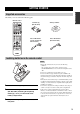
GETTING STARTED GETTING STARTED INTRODUCTION Supplied accessories Check that you received all of the following parts. Remote control CODE SET Batteries (2) (AA, R6, UM-3) TRANSMIT POWER POWER TV AV CD CD-R STANDBY POWER MD AM loop antenna SLEEP XM MULTI CH IN CBL DVD DTV TUNER V-AUX DVR TV VOL TV CH VOLUME TV MUTE TV INPUT MUTE MUSIC ENTERTAIN AMP SOURCE TV STEREO MOVIE 1 2 3 4 STANDARD SELECT EXTD SUR. DIRECT ST.
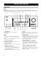
CONTROLS AND FUNCTIONS CONTROLS AND FUNCTIONS Front panel Note The XM Satellite Radio controlling functions in the following buttons (SEARCH MODE, CATEGORY, PRESET/TUNING/CH l / h, MEMORY, and DISPLAY) are only applicable to the U.S.A. model and are operational only when “XM” is selected as the input source. For details, see “XM Satellite Radio controls and functions” on page 53.
CONTROLS AND FUNCTIONS F BASS/TREBLE +/– Adjusts the bass/treble balance of the front left and right speakers in conjunction with TONE CONTROL (see page 32). 9 TUNING MODE (AUTO/MAN’L) Switches between automatic tuning (the AUTO indicator is turned on) and manual tuning (the AUTO indicator is turned off) (see page 45). G PROGRAM l / h Selects sound field programs (see page 32).
CONTROLS AND FUNCTIONS Remote control This section describes the function of each control on the remote control used to control this unit. To operate other components, see “REMOTE CONTROL FEATURES” on page 90. Notes • The XM Satellite Radio controlling functions in the following buttons (XM, XM MEMORY, SRCH MODE, DISPLAY, cursor buttons u / d / j / i, numeric buttons and ENT.) are only applicable to the U.S.A. model and are operational only when “XM” is selected as the input source.
CONTROLS AND FUNCTIONS 8 Cursor buttons u / d / j / i, ENTER Select and adjust the sound field program parameters or the “SET MENU” parameters. 0 TRANSMIT indicator Flashes while the remote control is sending infrared signals. A STANDBY Sets this unit to the standby mode (see page 27). B POWER Turns on this unit (see page 27). INTRODUCTION 9 RETURN Returns to the previous menu level when adjusting the “SET MENU” parameters. H STRAIGHT (EFFECT) Turns the sound field programs off or on.
CONTROLS AND FUNCTIONS ■ Controlling the TUNER functions ■ Using the remote control Set the component selector switch to SOURCE and then press TUNER to select “TUNER” as the input source. The remote control transmits a directional infrared ray. Be sure to aim the remote control directly at the remote control sensor on this unit during operation. 4 Numeric buttons Use numbers 1 through 8 to select preset stations. (U.S.A. model) 7 BAND Switches the reception band between FM and AM (see page 45).
CONTROLS AND FUNCTIONS Front panel display INTRODUCTION Note The XM indicator is only applicable to the U.S.A. model and the cursor on the left of the XM indicator lights up only when “XM” is selected as the input source. For details, see “Basic XM Satellite Radio operations” on page 55.
CONTROLS AND FUNCTIONS C VOLUME level indicator Indicates the current volume level. D PCM indicator Lights up when this unit is reproducing PCM (Pulse Code Modulation) digital audio signals. E STANDARD indicator Lights up when the “SUR. STANDARD” or “SUR. ENHANCED” program is selected (see page 42). F SP A B indicators Light up according to the set of front speakers selected. G Headphones indicator Lights up when headphones are connected (see page 33).
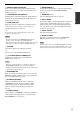
CONTROLS AND FUNCTIONS Rear panel 2 AUDIO 3 AUDIO 4 5 MULTI CH INPUT OUTPUT CENTER 6 DIGITAL OUTPUT MD/CD-R DIGITAL INPUT MD/CD-R DVD DTV/CBL 7 8 XM DOCK 9 INTRODUCTION 1 DVD COMPONENT VIDEO DVD Y MD/ OUT (PLAY) CD-R (REC) IN CD DVD DTV/CBL IN DVR OUT VIDEO TUNER AM ANT GND MONITOR OUT DVD DTV/CBL FRONT IN SURROUND DVR OUT S VIDEO SUB WOOFER SUB WOOFER OPTICAL OPTICAL PB DVR PR Y PB PR COAXIAL MONITOR OUT DTV/CBL MONITOR OUT SPEAKERS FM ANT 75Ω UNBAL.
CONNECTIONS CONNECTIONS Placing speakers The speaker layout below shows the standard ITU-R* speaker setting. You can use it to enjoy CINEMA DSP and multi-channel audio sources. * ITU-R is the radio communication sector of the ITU (International Telecommunication Union). FL Center speaker (C) The center speaker is for the center channel sounds (dialog, vocals, etc.). If for some reason it is not practical to use a center speaker, you can do without it.
CONNECTIONS Connecting speakers Be sure to connect the left channel (L), right channel (R), “+” (red) and “–” (black) properly. If the connections are faulty, no sound will be heard from the speakers, and if the polarity of the speaker connections is incorrect, the sound will be unnatural and lack bass. CAUTION Notes • A speaker cord is actually a pair of insulated cables running side by side. Cables are colored or shaped differently, perhaps with a stripe, groove or ridge.
CONNECTIONS FRONT terminals Connect one or two front speaker systems (1, 2) to these terminals. If you use only one front speaker system, connect it to the FRONT A or B terminal. CENTER terminals Connect a center speaker (3) to these terminals. SURROUND terminals Connect surround speakers (4, 5) to these terminals. SURROUND BACK terminals Connect a surround back speaker (6) to these terminals.
CONNECTIONS ■ Connecting the speaker cable ■ Connecting the banana plug 1 The banana plug is a single-pole electrical connector widely used to terminate speaker cables. Remove approximately 10 mm (0.4 in) of insulation from the end of each speaker cable and then twist the exposed wires of the cable together to prevent short circuits. Banana plug 10 mm (0.4 in) 2 Insert the banana plug connector into the end of the corresponding terminal. Loosen the knob.
CONNECTIONS Information on jacks and cable plugs Note You can use the digital jacks to input PCM, Dolby Digital and DTS bitstreams. When you connect components to both the COAXIAL and OPTICAL jacks, priority is given to the signals input at the COAXIAL jack. All digital input jacks are compatible with 96-kHz sampling digital signals.
CONNECTIONS Audio and video signal flow ■ Audio signal flow for AUDIO OUT (REC) Input Output AUDIO OUT (REC) DIGITAL AUDIO COAXIAL Digital audio L R L PREPARATION DIGITAL AUDIO OPTICAL R AUDIO Analog audio PORTABLE Digital output Analog output Note This unit handles digital and analog signals independently. Thus, audio signals input at the analog jacks are output only at the analog AUDIO OUT (REC) jacks.
CONNECTIONS Connecting a TV Connect your TV to the VIDEO MONITOR OUT jack, the S VIDEO MONITOR OUT jack or the COMPONENT VIDEO MONITOR OUT jacks of this unit. CAUTION Do not connect this unit or other components to the AC power supply until all connections between components are complete. (U.S.A.
CONNECTIONS Connecting a DVD player, a DVD recorder, a VCR or an STB Connect your DVD player, DVD recorder, VCR or STB (set-top box) using the same type of video connections as those made for your TV (see page 18). The cable TV receiver and the satellite receiver are examples of the STB. CAUTION Do not connect this unit or other components to the AC power supply until all connections between components are complete.
CONNECTIONS ■ Connecting a DVD recorder or a VCR (U.S.A. model) AUDIO COMPONENT VIDEO DVR Y DVR OUT IN DVR OUT L V V S S-video in R S-video out L Video out Audio in Audio out R PR S VIDEO Video in IN VIDEO PB S Y PB PR Component video out DVD recorder or VCR ■ Connecting an STB Cable TV receiver or satellite receiver S O AUDIO Optical audio out V S-video out L Video out R Audio out Component video out Y PB PR (U.S.A.
CONNECTIONS Connecting a CD player, an MD player or a tape deck Connect your CD player, MD player or tape deck via analog and/or digital connections. CAUTION Do not connect this unit or other components to the AC power supply until all connections between components are complete. Note CD player Audio out R L (U.S.A.
CONNECTIONS Connecting a YAMAHA iPod universal dock This unit is equipped with the DOCK terminal on the rear panel that allows you to connect a YAMAHA iPod universal dock (such as YDS-10 sold separately) where you can station your iPod and control playback of your iPod using the supplied remote control. Connect a YAMAHA iPod universal dock (such as YDS-10 sold separately) to the DOCK terminal on the rear panel of this unit using its dedicated cable.
CONNECTIONS Connecting a multi-format player or an external decoder This unit is equipped with 6 additional input jacks (FRONT L/R, CENTER, SURROUND L/R and SUBWOOFER) for discrete multi-channel input from a multi-format player, external decoder or sound processor. Connect the output jacks on your multi-format player or external decoder to the MULTI CH INPUT jacks. Be sure to match the left and right output jacks to the left and right input jacks for the front and surround channels.
CONNECTIONS Connecting the FM and AM antennas Both FM and AM indoor antennas are supplied with this unit. In general, these antennas should provide sufficient signal strength. Connect each antenna correctly to the designated terminals. 2 Press and hold the tab of the AM ANT terminal. 3 Insert one of the AM loop antenna lead wires into the AM ANT terminal. 4 Release the tab of the AM ANT terminal back into place. 5 Repeat steps 2 through 4 to connect the other lead wire to the GND terminal.
CONNECTIONS Connecting the power cable Once all connections are complete, plug the power cable into the AC wall outlet. (U.S.A. model) PREPARATION AC OUTLETS To the AC wall outlet ■ AC OUTLET(S) (SWITCHED) Australia model...................................................... 1 outlet Other models......................................................... 2 outlets Use these outlet(s) to supply power to any connected components. Connect the power cable of your other components to these outlet(s).
CONNECTIONS Setting the speaker impedance CAUTION 4 If you are to use 4 or 6 ohm speakers, set “SP IMP.” to “6ΩMIN” as follows BEFORE using this unit. Press STRAIGHT (EFFECT) on the front panel repeatedly to select “6ΩMIN”. The following display appears in the front panel display. STRAIGHT 2,5 (U.S.A.
CONNECTIONS Turning on this unit or setting it to the standby mode When all connections are complete, turn on this unit. STANDBY/ON (U.S.A. model) (U.S.A.
BASIC SETUP BASIC SETUP The “BASIC SETUP” feature is a useful way to set up your system quickly and with minimal effort. Notes • Make sure you disconnect your headphones from this unit. • If you wish to configure this unit manually using more precise adjustments, use the detailed parameters in “SOUND MENU” (see page 78). • Altering any parameters in “BASIC SETUP” resets all parameters manually adjusted in “SOUND MENU” (see page 78). • Initial settings are indicated in bold under each parameter.
BASIC SETUP 6 Press d to select “SUBWOOFER” and then j / i to select the desired setting. PRESET/CH Press d to select “SETUP” and then j / i to select the desired setting. PRESET/CH ;BASIC SETUP ENTER A-E/CAT. 8 A-E/CAT. ROOM: S >M L . SUBWOOFER;;;;YES SPEAKERS;;;;6spk SETUP:>OK CANCEL ;BASIC SETUP ROOM: S >M L SUBWOOFER;;;;YES SPEAKERS;;;;6spk . SETUP:>OK CANCEL ENTER A-E/CAT. A-E/CAT.
BASIC SETUP 10 Press j / i to select the desired setting. ;BASIC SETUP PRESET/CH ROOM: S >M L SUBWOOFER;;;;YES SPEAKERS;;;;6spk SETUP:>OK CANCEL . CHECK OK?;;;;YES ENTER A-E/CAT. 12 A-E/CAT. Press u / d to select a speaker and then j / i to adjust the balance. The selected speaker and the front left speaker (or the surround left speaker) output a test tone in turn. • Press i to increase the value. • Press j to decrease the value.
PLAYBACK PLAYBACK CAUTION Extreme caution should be exercised when you play back CDs encoded in DTS. If you play back a CD encoded in DTS on a DTS-incompatible CD player, you will only hear some unwanted noise that may damage your speakers. Check whether your CD player supports CDs encoded in DTS. Also, check the sound output level of your CD player before you play back a CD encoded in DTS. (U.S.A.
PLAYBACK 5 Rotate VOLUME on the front panel (or press VOLUME +/– on the remote control) to adjust the volume to the desired output level. VOLUME or VOLUME 7 Press PROGRAM l / h on the front panel (or press one of the sound field program selector buttons on the remote control) repeatedly to select the desired sound field program. The name of the selected sound field program appears in the front panel display and in the OSD. See page 64 for details about sound field programs.
USING AUDIO FEATURES USING AUDIO FEATURES Using SILENT CINEMA SILENT CINEMA allows you to enjoy multi-channel music or movie sound, including Dolby Digital and DTS sources, through ordinary headphones. SILENT CINEMA activates automatically whenever you connect headphones to the PHONES jack while listening to CINEMA DSP or HiFi DSP sound field programs (see page 64). When activated, the SILENT CINEMA indicator lights up in the front panel display.
USING AUDIO FEATURES y AUTO “NIGHT:CINEMA” and “NIGHT:MUSIC” adjustments are stored independently. Notes DTS • You cannot use the night listening modes in the following cases: – when the “DIRECT STEREO” mode (see page 38) is selected. – when the component connected to the MULTI CH INPUT jacks is selected as the input source (see page 37). – when headphones are connected to the PHONES jack.
USING AUDIO FEATURES 3 Press SLEEP on the remote control repeatedly to set the amount of time. Each time you press SLEEP, the front panel display changes as shown below. SLEEP Adjusting the speaker level You can adjust the output level of each speaker while listening to a music source. This is also possible when playing sources input at the MULTI CH INPUT jacks. Note This operation will override the level adjustments made in “BASIC SETUP” (see page 28) and “SPEAKER LEVEL” (see page 80).
USING AUDIO FEATURES 2 Press j / i on the remote control to adjust the speaker output level. • Press i to increase the value. • Press j to decrease the value. Control range: –10 dB to +10 dB PRESET/CH ENTER A-E/CAT. 3 A-E/CAT. Press ENTER on the remote control when you have completed your adjustment. PRESET/CH ENTER A-E/CAT. A-E/CAT.
USING AUDIO FEATURES 1 Set the component selector switch to AMP and then press ENHANCER on the remote control repeatedly to select the desired Compressed Music Enhancer mode. The following display is shown in the OSD and the ENHANCER indicator lights up in the front panel display. AMP ENHANCER SOURCE 0 Selecting the MULTI CH INPUT component Use this feature to select the component connected to the MULTI CH INPUT jacks (see page 23) as the input source.
USING AUDIO FEATURES Enjoying multi-channel sources in 2-channel stereo You can mix down multi-channel sources to 2 channels and enjoy playback in 2-channel stereo. Set the component selector switch to AMP and then press STEREO on the remote control repeatedly to select “2ch Stereo”. Enjoying pure hi-fi stereo sound The “DIRECT STEREO” mode allows sources to bypass the decoders and DSP processors of this unit so that you can enjoy pure hi-fi sound from 2-channel PCM and analog sources.
USING VIDEO FEATURES USING VIDEO FEATURES Signal format FORMAT Signal format display. When this unit cannot detect a digital signal, it automatically switches to analog input. Display status: Analog, Digital, Dolby D, DTS, PCM, --- Displaying the input source information You can display the format, sampling frequency, channel, bit rate and flag data of the current input signal. 1 Note Set the component selector switch to AMP and then press SET MENU on the remote control.
USING VIDEO FEATURES Selecting the OSD mode You can display the operating information of this unit on a video monitor. If you display the “SET MENU” and sound field program parameter settings on a video monitor, it is much easier to see the available options and parameters than it is to read the information in the front panel display. 1 Turn on the video monitor connected to this unit.
ENJOYING SURROUND SOUND ENJOYING SURROUND SOUND Enjoying multi-channel sources in surround If you connected a surround back speaker, use this feature to enjoy 6.1-channel playback for multi-channel sources using the Dolby Pro Logic IIx, Dolby Digital EX or DTS-ES decoders. 1 Set the component selector switch to AMP and then press EXTD SUR. on the remote control repeatedly to switch between 5.1 and 6.1-channel playback.
ENJOYING SURROUND SOUND Enjoying 2-channel sources in surround Signals input from 2-channel sources can also be played back on multi-channels. 1 Set the component selector switch to AMP and then press STANDARD on the remote control repeatedly to switch between the “SUR. STANDARD” and “SUR. ENHANCED” programs or press MOVIE to select the “MOVIE THEATER” program. SUR.
ENJOYING SURROUND SOUND Using Virtual CINEMA DSP Virtual CINEMA DSP allows you to enjoy the CINEMA DSP programs without surround speakers. It creates virtual speakers to reproduce the natural sound field. If you set “SUR. L/R SP” to “NONE” (see page 79), Virtual CINEMA DSP activates automatically whenever you select a CINEMA DSP sound field program (see page 64). Note Virtual CINEMA DSP will not activate even when “SUR.
RECORDING RECORDING Recording adjustments and other operations are performed from the recording components. Refer to the operating instructions for those components. CAUTION The DTS signal is a digital bitstream. Attempting to digitally record the DTS bitstream will result in noise being recorded. Therefore, if you want to use this unit to record sources encoded in DTS, the following considerations and adjustments need to be made.
FM/AM TUNING FM/AM TUNING There are 2 tuning methods: automatic and manual. Automatic tuning is effective when station signals are strong and there is no interference. If the signal from the station you want to select is weak, tune into it manually. You can also use the automatic and manual preset tuning features to store up to 40 stations (A1 to E8: 8 preset station numbers in each of the 5 preset station groups).
FM/AM TUNING Manual tuning 3 If the signal received from the station you want to select is weak, tune into it manually. Press TUNING MODE (AUTO/MAN’L) so that the AUTO indicator disappears from the front panel display. TUNING MODE Note DISPLAY AUTO/MAN'L Manually tuning into an FM station automatically switches the tuner to monaural reception to increase the signal quality. 2 (U.S.A.
FM/AM TUNING Automatic preset tuning 3 You can use the automatic preset tuning feature to store FM stations with strong signals up to 40 (A1 to E8: 8 preset station numbers in each of the 5 preset station groups) of those stations in order. You can then recall any preset station easily by selecting the preset station number. 2 3 Press and hold MEMORY (MAN’L/AUTO FM) for more than 3 seconds. The preset station number as well as the MEMORY and AUTO indicators flashes.
FM/AM TUNING ■ Automatic preset tuning options You can specify the preset number from which this unit stores FM stations and/or begins tuning toward lower frequencies. Note Manual preset tuning You can also store up to 40 stations (A1 to E8: 8 preset station numbers in each of the 5 preset station groups) manually. First carry out steps 1 through 3 in “Automatic preset tuning” on page 47.
FM/AM TUNING 4 Press PRESET/TUNING/CH l / h to select a preset station number (1 to 8) while the MEMORY indicator is flashing. • Press h to select a higher preset station number. • Press l to select a lower preset station number. Selecting preset stations You can tune into any desired station simply by selecting the preset station group and number under which it was stored. 1 2 l PRESET/TUNING/CH h (U.S.A.
FM/AM TUNING 2 Press PRESET/TUNING/CH l / h on the front panel (or PRESET/CH u / d on the remote control) to select the desired preset station number (1 to 8). The preset station group and number appear in the front panel display along with the station band and frequency. Exchanging preset stations You can exchange the assignments of two preset stations with each other. The example below describes the procedure to exchange preset station “E1” with “A5”. 2,4 1,3 (U.S.A.
FM/AM TUNING 3 Select preset station “A5” using A/B/C/D/E and PRESET/TUNING/CH l / h. “A5” and the MEMORY indicator flash in the front panel display. See “Selecting preset stations” on page 49. l PRESET/TUNING/CH h A/B/C/D/E CATEGORY NEXT LEVEL Flashes DVR V-AUX DTV/CBL DVD MD/CD-R pTUNER TUNED CD XM VOLUME MEMORY SP A dB A5:FM 90.6 MHz L R Flashes BASIC OPERATION 4 Press EDIT again.
XM® SATELLITE RADIO TUNING XM® SATELLITE RADIO TUNING XM Satellite Radio is the satellite radio service with millions of listeners across the United States, broadcasting live daily.
XM® SATELLITE RADIO TUNING XM Satellite Radio controls and functions Note The following controls are available only when “XM” is selected as the input source. Rotate the INPUT selector on the front panel (or set the component selector switch to SOURCE and then press XM on the remote control) to select “XM” as the input source. ■ Front panel functions ■ Remote control functions (U.S.A.
XM® SATELLITE RADIO TUNING Activating XM Satellite Radio 2 To sign up for an account with the XM Satellite Radio service, an XM Satellite Radio ID number is required. Follow the procedure below to check your ID number, and then visit the website at “http://activate.xmradio.com/” or call “1-800-XM-RADIO (1-800-967-2346)” with a major credit card handy for signing up.
XM® SATELLITE RADIO TUNING Basic XM Satellite Radio operations TV AV CD CD-R XM DVD DTV V-AUX DVR TV VOL TV CH • You can use the Neural Surround decoder to enjoy the surround sound content of the XM Satellite Radio broadcasts in multi-channels (see page 42). • You can set the XM Satellite Radio preset channels (see page 60). • You can display the XM Satellite Radio information in the front panel display or in the OSD (see page 61).
XM® SATELLITE RADIO TUNING Selecting the XM Satellite Radio search mode 2 You can search for the desired channel using one of the three search modes (All Channel Search, Category Search, and Preset Search modes). You can also enter the channel number directly to select the desired channel by using the Direct Number Access mode (see page 59). Press SEARCH MODE on the front panel (or SRCH MODE on the remote control) repeatedly to select “ALL CH SEARCH”.
XM® SATELLITE RADIO TUNING ■ Category Search mode 2 2 3 (U.S.A. model) Press SEARCH MODE on the front panel (or SRCH MODE on the remote control) repeatedly to select “CAT SEARCH”.
XM® SATELLITE RADIO TUNING ■ Preset Search mode Prior to selecting a preset channel in the Preset Search mode, you must preset XM Satellite Radio channels. For details, see “Setting the XM Satellite Radio preset channels” on page 60. 2 Press SEARCH MODE on the front panel (or SRCH MODE on the remote control) repeatedly to select “PRESET SEARCH”. SET MENU PRESET/TUNING y All preset channels (A1 to E8) recalls “001 Preview” by the initial factory setting.
XM® SATELLITE RADIO TUNING ■ Direct Number Access mode TV MD 1 3 AV CD-R CD SLEEP XM MULTI CH IN CBL DVD DTV V-AUX DVR MUSIC STEREO 3 ENTERTAIN MOVIE 1 2 3 4 STANDARD SELECT EXTD SUR. DIRECT ST. 5 6 7 8 SPEAKERS ENHANCER NIGHT STRAIGHT 9 0 TUNER 3 2 ENT. 10 EFFECT AMP SOURCE TV VOL TV CH VOLUME TV PRESET/CH 1 LEVEL SET MENU TITLE MENU SRCH MODE BAND ENTER A-E/CAT.
XM® SATELLITE RADIO TUNING Setting the XM Satellite Radio preset channels 2 You can use this feature to store up to 40 XM Satellite Radio channels (A1 to E8: 8 preset channel numbers in each of the 5 preset channel groups). You can then recall any preset channel easily by selecting the preset channel group and number as described in “Preset Search mode” on page 58. 3 2,5 Press MEMORY on the front panel (or XM MEMORY on the remote control).
XM® SATELLITE RADIO TUNING 4 Press PRESET/TUNING/CH l / h on the front panel (or PRESET/CH u / d on the remote control) repeatedly to select a preset channel number (1 to 8) while the MEMORY indicator is flashing. The preset channel number appears in the front panel display.
XM® SATELLITE RADIO TUNING When the channel number / name is displayed: DVR V-AUX DTV/CBL DVD MD/CD-R TUNER CD pXM VOLUME SP A dB [040] Deep Tra L R ■ Displaying the XM Satellite Radio information in the OSD Press DISPLAY on the front panel or on the remote control. The following screen is displayed in the OSD.
SOUND FIELD PROGRAMS SOUND FIELD PROGRAMS What really creates the rich, full tones of a live instrument are the multiple reflections from the walls of the room. In addition to making the sound live, these reflections enable us to tell where the player is situated as well as the size and shape of the room in which we are sitting.
SOUND FIELD PROGRAMS Sound field program descriptions This unit is equipped with a variety of precise digital decoders that allow you to enjoy multi-channel playback from almost any stereo or multi-channel sound source. This unit is also equipped with a YAMAHA digital sound field processing (DSP) chip containing several sound field programs which you can use to enhance your playback experience. y The YAMAHA CINEMA DSP modes are compatible with all Dolby Digital, DTS, and Dolby Surround sources.
SOUND FIELD PROGRAMS Remote control button Sound field program Features MOVIE THEATER Spectacle CINEMA DSP processing. This program reproduces the extremely wide sound field of a 70-mm movie theater in detail, making both the video and the sound field incredibly real. This is ideal for any kind of video source encoded in Dolby Surround, Dolby Digital or DTS, especially large-scale movie productions. MOVIE THEATER Sci-Fi CINEMA DSP processing.
SOUND FIELD PROGRAMS Changing sound field parameter settings 2 Turn on the video monitor and then press DISPLAY on the remote control. The following display is shown in the OSD. You can enjoy good quality sound with the initial factory settings. Although you do not have to change the initial factory settings, you can change some of the parameters to better suit the input source or your listening room. DISPLAY Notes • Use the “PARAM.
SOUND FIELD PROGRAMS ■ Sound field parameter descriptions You can adjust the values of certain digital sound field parameters so that the sound fields are recreated accurately in your listening room. Not all of the following parameters are found in every program. y To change sound field parameter settings to suit your listening environment, see page 66 for details. Sound field parameter DSP LEVEL Features DSP level. Adjusts the level of all the DSP effect sounds within a narrow range.
SOUND FIELD PROGRAMS Sound field parameter ROOM SIZE P.ROOM SIZE S.ROOM SIZE SB ROOM SIZE Features Room size. Presence, surround, and surround back room size. Adjusts the apparent size of the surround sound field. The larger the value, the larger the surround sound field becomes. As the sound is repeatedly reflected around a room, the larger the hall is, the longer the time between the original reflected sound and the subsequent reflections.
SOUND FIELD PROGRAMS Sound field parameter REV.TIME Features Reverberation time. Adjusts the amount of time taken for the dense, subsequent reverberation sound to decay by 60 dB at 1 kHz. This changes the apparent size of the acoustic environment over an extremely wide range. Set a longer reverberation time for “dead” sources and listening room environments, and a shorter time for “live” sources and listening room environments. Control range: 1.0 to 5.
SOUND FIELD PROGRAMS Sound field parameter REV.LEVEL Features Reverberation level. Adjusts the volume of the reverberation sound. The larger the value, the stronger the reverberation becomes. Level Control range: 0 to 100% Source sound (dB) 60 dB Reverberation Time REV.DELAY 2ch Stereo DIRECT REV.TIME 2-channel stereo direct. Bypasses the decoders and DSP processors of this unit for pure hi-fi stereo sound when playing 2-channel analog sources.
SOUND FIELD PROGRAMS Sound field parameter Features PRO LOGIC IIx Music PRO LOGIC II Music PANORAMA Pro Logic IIx Music and Pro Logic II Music panorama. Sends stereo signals to the surround speakers as well as the front speakers for a wraparound effect. PRO LOGIC IIx Music PRO LOGIC II Music DIMENSION Pro Logic IIx Music and Pro Logic II Music dimension. Adjusts the sound field either towards the front or towards the rear.
SOUND FIELD PROGRAMS Sound field program speaker layouts Sound output from each speaker depends on the type of audio signals being input. Refer to the diagrams in the table below to understand the speaker layout for each sound field program. Note Be advised that there may be no or not enough sound output from speakers depending on the type of input source being played back.
SOUND FIELD PROGRAMS Sound field program MOVIE THEATER Spectacle Sci-Fi Adventure General 2-channel audio (monaural) L SL SUR. STANDARD DOLBY DIGITAL PRO LOGIC DTS L SL C SB R L SR SL R L SR SL C SB 2-channel audio (stereo) Pro Logic SUR. STANDARD PLII Movie PLII Music PLII Game PLIIx Movie PLIIx Music PLIIx Game L SL C SB C SB R L SR SL R L SR SL C SB 5.1/6.
SOUND FIELD PROGRAMS Sound field program SUR. ENHANCED DOLBY DIGITAL PRO LOGIC DTS 2-channel audio (monaural) L SL C SB 2-channel audio (stereo) R L SR SL Pro Logic SUR. ENHANCED PLII Movie PLIIx Movie L SL C SB C SB 5.1/6.1-channel audio * R L SR SL C SB R SR Pro Logic R L SR SL C SB R SR Pro Logic II L SL C SB R SR Pro Logic IIx SUR.
SET MENU SET MENU You can use the following parameters in “SET MENU” to adjust a variety of system settings and customize the way this unit operates. Change the initial settings (indicated in bold under each parameter) to reflect the needs of your listening environment. ■ Basic setup BASIC SETUP Use this feature to set up your system quickly and with minimal effort (see page 28). ■ Manual setup MANUAL SETUP Use this feature to manually adjust speaker and system parameters.
SET MENU Option menu 3 OPTION MENU Use this menu to manually adjust the optional system parameters. Parameter Features Page A)DISPLAY SET Adjusts the brightness of the display and converts video signals. 85 B)MEMORY GUARD Locks sound field program parameters and other “SET MENU” settings. 86 C)PARAM. INI Initializes the parameters of a group of sound field programs. 86 D)MULTI ZONE SET Specifies the location of the speakers connected to the SPEAKERS B terminals.
SET MENU Using SET MENU 2 Press u / d to select “MANUAL SETUP”. Use the remote control to access and adjust each parameter. TV AV CD CD-R MUSIC STEREO MD SLEEP 2 3 4 SELECT EXTD SUR. DIRECT ST. 5 6 7 8 SPEAKERS ENHANCER NIGHT STRAIGHT 9 0 ENTER A-E/CAT. A-E/CAT. TUNER DVR 10 [ ]/[ ]:Up/Down [ENTER]:Enter p V-AUX MOVIE 1 STANDARD p MULTI CH IN DTV SET MENU ;BASIC SETUP . ;MANUAL SETUP . ;SIGNAL INFO XM CBL DVD ENTERTAIN PRESET/CH ENT.
SET MENU 5 Press u / d repeatedly and then press ENTER to select and enter the desired submenu. The following display is an example where “SPEAKER LEVEL” is selected. PRESET/CH Use this menu to manually adjust any speaker settings or compensate for video signal processing delays when using LCD monitors or projectors. 1 SOUND MENU 1/2 PRESET/CH ENTER p A-E/CAT. 1 SOUND MENU 2/2 . E)LFE LEVEL F)DYNAMIC RANGE G)AUDIO SET [ ]/[ ]:Up/Down [ENTER]:Enter p A-E/CAT. p A-E/CAT.
SET MENU Center speaker CENTER SP Choices: NONE, SML, LRG CENTER SP Surround back speakers SUR. B SP Choices: NONE, SML, LRG SUR. B SP NONE >SML LRG NONE >SML LRG • Select “NONE” (none) if you did not connect a center speaker. The low-frequency signals of the center channel are directed to the speakers selected in “LFE/ BASS OUT”, and the rest of the center channel signals are directed to the front left and right speakers.
SET MENU Crossover CROSS OVER Use this feature to select a crossover frequency of all the speakers set to “SML” (or “SMALL”) or to “NONE” in “SPEAKER SET” (see pages 78 and 79). All frequencies below the selected frequency will be sent to the subwoofer or to the speakers set to “LRG” (or “LARGE”) in “SPEAKER SET” (see pages 78 and 79).
SET MENU ■ Speaker distance C)SP DISTANCE ■ Center graphic equalizer D)CENTER GEQ Use this feature to manually adjust the distance of each speaker and the delay applied to the respective channel. Ideally, each speaker should be the same distance from the main listening position. However, this is not possible in most home situations. Thus, a certain amount of delay must be applied to the sound from each speaker so that all sounds will arrive at the listening position at the same time.
SET MENU ■ Dynamic range F)DYNAMIC RANGE Use this feature to select the amount of dynamic range compression to be applied to your speakers or headphones. This setting is effective only when this unit is decoding Dolby Digital and DTS signals. ■ Audio settings G)AUDIO SET Use this feature to adjust the overall audio settings of this unit. G)AUDIO SET F)DYNAMIC RANGE p [ ]/[ ]:Up/Down [<]/[>]:Select p . SP: MIN STD>MAX HP: MIN STD>MAX .
SET MENU 2 INPUT MENU Use this menu to reassign the input/output jacks, select the input mode or rename the input source. 2 INPUT MENU p p .
SET MENU ■ Input mode B)INPUT MODE Use this feature to set this unit to reset “INPUT MODE” back to “AUTO” (see page 34) regardless of the previous setting or to recall the last input mode (“AUTO”, “DTS”, or “ANALOG”) used for that source whenever you turn on this unit. Choices: AUTO, LAST 2 Set the component selector switch to AMP and then press j / i on the remote control to place the “_” (underscore) under the space or the character you want to edit.
SET MENU ■ Volume Trim D)VOLUME TRIM Use this menu to adjust the optional system parameters. 3 OPTION MENU 1/2 3 OPTION MENU 2/2 . E)XM RADIO SET p . A)DISPLAY SET B)MEMORY GUARD C)PARAM. INI D)MULTI ZONE SET [ ]/[ ]:Up/Down [ENTER]:Enter p [ ]/[ ]:Up/Down [ENTER]:Enter p D)VOLUME TRIM DVD -> 0.0dB 3 OPTION MENU p Use this feature to adjust the level of the signal input at each jack.
SET MENU OSD shift OSD SHIFT Use this feature to adjust the vertical position of the OSD. Control range: –5 (upward) to +5 (downward) Control step: 1 Initial setting: 0 • Press j to raise the position of the OSD. • Press i to lower the position of the OSD. Gray back GRAY BACK Use this feature to display a gray background in the OSD when there is no video signal being input. Choices: AUTO, OFF • Select “AUTO” to display a gray background in the OSD when there is no video signal being input.
SET MENU ■ Zone set D)MULTI ZONE SET Use this feature to specify the location of speakers connected to the SPEAKERS B terminals of this unit. ■ XM Radio setting E)XM RADIO SET (U.S.A. model only) E)XM RADIO SET D)MULTI ZONE SET . XM DISPLAY;;;10S XM ANTENNA;;NONE SCROLL;;;;;;CONT .
ADVANCED SETUP ADVANCED SETUP This unit has additional menus that are displayed in the front panel display. The advanced setup menu offers additional operations to adjust and customize the way this unit operates. Change the initial settings (indicated in bold under each parameter) to reflect the needs of your listening environment. Notes • The settings you make are reflected next time you turn on this unit by pressing STANDBY/ON on the front panel (or POWER on the remote control) (see page 27).
ADVANCED SETUP ■ Speaker impedance SP IMP. Use this feature to set the speaker impedance of this unit so that it matches that of your speakers. Choices: 8ΩMIN, 6ΩMIN • Select “8ΩMIN” to set the speaker impedance to 8 Ω . • Select “6ΩMIN” to set the speaker impedance to 6 Ω . SP IMP. Speaker Impedance level If you use one set (A or B), the impedance of each speaker must be 8 Ω or higher. Front If you use two sets (A and B), the impedance of each speaker must be 16 Ω or higher.
REMOTE CONTROL FEATURES REMOTE CONTROL FEATURES In addition to controlling this unit, the remote control can also operate other audiovisual components made by YAMAHA and other manufacturers. To control your TV or other components, you must set the appropriate remote control code for each input source (see page 92). Controlling this unit, a TV, or other components ■ Controlling this unit ■ Controlling a TV Set the component selector switch to AMP to control this unit.
REMOTE CONTROL FEATURES ■ Controlling other components Set the component selector switch to SOURCE to control other components selected with the input selector buttons, , or . You must set the appropriate remote control code for each input source (see page 92). The following table shows the function of each control button used to control other components assigned to each input selector button, , and . Be advised that some buttons may not correctly operate the selected component.
REMOTE CONTROL FEATURES Setting the remote control code 1 You can control your TV and other components by setting the appropriate remote control code for each input source. For a complete list of available remote control codes, refer to “LIST OF REMOTE CONTROL CODES” at the end of this manual. Press one of the input selector buttons or / to select the component you want to set up.
REMOTE CONTROL FEATURES ■ Setting remote control TUNER ID library codes Setting library codes You can operate multiple YAMAHA receivers or amplifiers in the same room with the supplied remote control simultaneously. Set the appropriate library code to select and operate the desired component with the supplied remote control. Select one of the following codes to set the remote control TUNER ID library code for the component you want to use.
REMOTE CONTROL FEATURES ■ Setting remote control XM ID library codes (U.S.A. model only) Select one of the following codes to set the remote control XM ID library code for the component you want to use. 1 Press XM to select “XM” as the input source. Resetting all remote control codes Use this feature to clear all the remote control codes previously set and reset all of them to the initial factory settings. 1 XM 2 Press CODE SET using a ballpoint pen or a similar object.
USING IPOD® USING iPod® Once you have stationed your iPod in a YAMAHA iPod universal dock (such as YDS-10 sold separately) connected to the DOCK terminal of this unit (see page 22), you can enjoy playback of your iPod using the supplied remote control. You can also use the Compressed Music Enhancer mode of this unit to improve the sound quality of the compression artifacts (such as the MP3 format) stored on your iPod (see page 36).
USING iPod® ■ Controlling iPod using the OSD Once “V-AUX” is selected as the input source, you can perform the advanced operations of your iPod using the supplied remote control with the aid of the OSD of this unit. You can also browse the songs stored on your iPod in the OSD. Further, you can change or adjust settings for your iPod to suit your personal preferences. Notes • Operations cannot be done with the controls on your iPod. • The YAMAHA logo appears in the display window of your iPod.
RESETTING THE SYSTEM RESETTING THE SYSTEM Use this feature to reset all the parameters of this unit to the initial factory settings. Notes • This procedure completely resets all the parameters of this unit including the “SET MENU” parameters. However, the advanced setup menu parameters will not be initialized. • The initial factory settings are activated next time you turn on this unit.
TROUBLESHOOTING TROUBLESHOOTING Refer to the table below when this unit does not function properly. If the problem you are experiencing is not listed below or if the instruction below does not help, set this unit to the standby mode, disconnect the power cable, and contact the nearest authorized YAMAHA dealer or service center. ■ General Problem This unit fails to turn on or enters the standby mode soon after the power is turned on.
TROUBLESHOOTING Problem The sound suddenly goes off. Cause See page Check that the speaker impedance setting is correct. 26, 89 Check that the speaker wires are not touching each other and then turn this unit back on. — The sleep timer has set this unit to the standby mode. Turn on this unit, and play the source again. — The sound is muted. Press MUTE or VOLUME +/– on the remote control to resume audio output. 33 Sound is heard from the speaker on one side only. Incorrect cable connections.
TROUBLESHOOTING Problem Cause Remedy See page Dolby Digital or DTS sources cannot be played. (Dolby Digital or DTS indicator in the front panel display does not light up.) The connected component is not set to output Dolby Digital or DTS digital signals. Make an appropriate setting following the operating instructions for your component. — “INPUT MODE” is set to “ANALOG”. Set “INPUT MODE” to “AUTO” or “DTS”. 34 A humming sound is heard. Incorrect cable connections.
TROUBLESHOOTING ■ Tuner Problem Cause FM stereo reception is noisy. FM AM ■ Remedy The characteristics of FM stereo broadcasts may cause this problem when the transmitter is too far away or the antenna input is poor. See page Check the antenna connections. 24 Try using a high-quality directional FM antenna. — Use the manual tuning method. 46 There is distortion, and clear reception cannot be obtained even with a good FM antenna. There is multi-path interference.
TROUBLESHOOTING ■ Remote control Problem The remote control does not work nor function properly. Cause Remedy See page Wrong distance or angle. The remote control functions within a maximum range of 6 m (20 ft) and no more than 30 degrees offaxis from the front panel. 8 Direct sunlight or lighting (from an inverter type of fluorescent lamp, etc.) is striking the remote control sensor of this unit. Reposition this unit. — The batteries are weak. Replace all batteries.
GLOSSARY GLOSSARY Audio information ■ Dolby Digital Dolby Digital is a digital surround sound system that gives you completely independent multi-channel audio. With 3 front channels (front L/R and center), and 2 surround stereo channels, Dolby Digital provides 5 full-range audio channels. With an additional channel especially for bass effects, called LFE (Low Frequency Effect), the system has a total of 5.1-channels (LFE is counted as 0.1 channel).
GLOSSARY ■ LFE 0.1 channel This channel reproduces low-frequency signals. The frequency range of this channel is from 20 Hz to 120 Hz. This channel is counted as 0.1 because it only enforces a low-frequency range compared to the full-range reproduced by the other 5/6 channels in Dolby Digital or DTS 5.1/6.1-channel systems. ■ Neo:6 Neo:6 decodes the conventional 2-channel sources for 6channel playback by the specific decoder.
GLOSSARY Sound field program information ■ CINEMA DSP Since the Dolby Surround and DTS systems were originally designed for use in movie theaters, their effect is best felt in a theater having many speakers designed for acoustic effects. Since home conditions, such as room size, wall material, number of speakers, and so on, can differ so widely, it is inevitable that there are differences in the sound heard.
SPECIFICATIONS SPECIFICATIONS AUDIO SECTION FM SECTION • Minimum RMS Output Power for Front, Center, Surround, Surround back 1 kHz, 0.7% THD, 8 Ω ....................................................... 110 W • Tuning Range [U.S.A. and Canada models] .......................... 87.5 to 107.9 MHz [Other models] ............................................ 87.50 to 108.00 MHz • Maximum Power (EIAJ) [China model] 1 kHz, 10% THD, 8 Ω .........................................................
LIST OF REMOTE CONTROL CODES CABLE TV RECEIVER ABC 10003, 10008, 10014, 10017, 10033 AMERICAST 10899 BELL & HOWELL 10014 BELL SOUTH 10899 CLEARMASTER 10883 CLEARMAX 10883 COOLMAX 10883 DIGEO 11187 DIGI 10637 DIRECTOR 10476 DUMONT 10637 GENERAL INSTRUMENT 10003, 10276, 10476, 10810 GOLDSTAR 10144 HAMLIN 10009, 10273 I3 MICRO 11602 JERROLD 10003, 10012, 10014, 10276, 10476, 10810 MACOM 10033 MEMOREX 10000 MOTOROLA 10014, 10276, 10476, 10810, 11187, 11254, 11376 MULTITECH 10883 MYRIO 11602 PACE 10008, 10237,
ROKU 11486 SAMSUNG 11190, 11490 SASEM 11641 SENSORY SCIENCE 11126 SHARP 11010 SMC 11456 SONY 11272, 11324, 11364 STACK 9 11272 STREAMZAP 11309 SYLVANIA 11563 SYSTEMAX 11272 TAGAR SYSTEMS 11272 TELEMANN 11604 TOSHIBA 11272 TOUCH 11272 VIEWSONIC 11272, 11329 VIZIO 11126 VOODOO 11272 ZT GROUP 11272 TV ADMIRAL ADVENT 20093, 20463 20761, 20783, 20815, 20817, 20842, 21933 AIKO 20092 AIWA 20701 AKAI 20030, 20060, 20672, 20702, 20812, 21903 ALBATRON 20700, 20843 AMERICA ACTION 20180 AMPRO 20751 ANAM 20180 AOC 200
SQUAREVIEW 20171 SSS 20180 STARLITE 20180 STUDIO EXPERIENCE 20843 SUPERSCAN 20093, 20864 SUPREME 20000 SVA 20587, 20748, 20865, 20870, 20871, 20872 SYLVANIA 20030, 20054, 20171, 21931, 21944 SYMPHONIC 20171, 20180, 21904 TANDY 20093 TATUNG 21756 TECHNICS 20051, 20250 TECHVIEW 20847 TECHWOOD 20051 TEKNIKA 20054, 20060, 20092, 20150, 20180 TELEFUNKEN 20702 THOMAS 21904 TMK 20178 TNCI 20017 TOSHIBA 20060, 20154, 20156, 20650, 20832, 20845, 21156, 21256, 21265, 21356, 21656, 21704, 21918, 21935, 21936, 21945 TV
STS SYLVANIA 30042 30035, 30043, 30081, 30593, 31593 SYMPHONIC 30593, 31593 SYSTEMAX 31972 TAGAR SYSTEMS 31972 TATUNG 30041 TEAC 30041 TECHNICS 30035, 30162 TEKNIKA 30035, 30037 TIVO 30618, 30636, 30739, 31503 TMK 30240 TOSHIBA 30043, 30045, 30209, 31008, 31972, 31988 TOTEVISION 30037, 30240 TOUCH 31972 UNITECH 30240 VECTOR 30045 VECTOR RESEARCH 30038 VIDEO CONCEPTS 30045 VIDEOMAGIC 30037 VIDEOSONIC 30240 VIEWSONIC 31972 VOODOO 31972 WARDS 30035, 30042, 30047, 30048, 30060, 30072, 30081, 30149, 30240 WHITE
PANASONIC 50490, 51010, 51011 PHILIPS 50646 PIONEER 50631, 51475, 51476 POLAROID 51086 RCA 50522 SAMSUNG 50490 SENSORY SCIENCE| 51158 SHARP 50675, 51550, 51556, 50630 SONY 51033, 51069, 51070, 51431 SYLVANIA 50675 TOSHIBA 51510 VICTOR 51275 YAMAHA 51544 ZENITH 50741 CD PLAYER AIWA 60157 ARCAM 60157 BURMESTER 60420 CALIFORNIA AUDIO LABS 60029, 60303 CARVER 60157, 60179 DENON 60003, 60034 DKK 60000 DMX ELECTRONICS 60157 FISHER 60179 GARRARD 60393, 60420 GENEXXA 60032 HARMAN/KARDON 60157 HITACHI 60032 INTEGR
HTR-5950_U_cv.fm Page 1 Monday, November 28, 2005 10:08 AM U TEAC TECHNICS THORENS TOSHIBA VICTOR 80163, 81074 80039, 80309, 81308, 81518 81189 80135 80074 WARDS XM YAMAHA 80014, 80054, 80158, 80189 81406, 81414 80176, 81176, 81276, 81331, 81375, 81908, (TUNER ID1) (TUNER ID2) (XM ID1) (XM ID 2) 81916 81917 81918 81919 OTHER AUDIO ACCESSORIES YAMAHA (iPod) 81981 HTR-5950 HTR-5950 AV Receiver © 2006 YAMAHA ELECTRONICS CORPORATION, USA 6660 ORANGETHORPE AVE., BUENA PARK, CALIF. 90620, U.S.A.