00_MCX-CA15_Owners_UB.
00_MCX-CA15_Owners_UB.book Page i Friday, April 30, 2004 10:53 AM COMPLIANCE INFORMATION STATEMENT (DECLARATION OF CONFORMITY PROCEDURE) Responsible Party: Address: Telephone: Fax: Type of Equipment: Model Name: Yamaha Electronics Corporation, U.S.A. 6660 Orangethorpe Avenue Buena Park, CA 90620 714-522-9105 714-670-0108 Distributed Audio Amplifier MCX-CA15 This device complies with Part 15 of the FCC Rules.
00_MCX-CA15_Owners_UB.book Page ii Friday, April 30, 2004 10:53 AM CAUTION: READ THIS BEFORE OPERATING YOUR UNIT. 1 To assure the finest performance, please read this manual carefully. Keep it in a safe place for future reference. 2 Install these units in a well ventilated, cool, dry, clean place — away from direct sunlight, heat sources, vibration, dust, moisture, and/or cold. Allow ventilation space of at least 10 cm on the top, bottom, left and right.
00_MCX-CA15_Owners_UB.book Page iii Friday, April 30, 2004 10:53 AM These units are not disconnected from the AC power source as long as they are connected to the wall outlet, even if the unit itself is turned off. This state is called the sleep mode. In this state, these units are designed to consume a very small quantity of power. WARNING TO REDUCE THE RISK OF FIRE OR ELECTRIC SHOCK, DO NOT EXPOSE THESE UNITS TO RAIN OR MOISTURE.
00_MCX-CA15_Owners_UB.book Page 1 Friday, April 30, 2004 10:53 AM CONTENTS INTRODUCTION INTRODUCTION FEATURES .............................................2 SUPPLIED ACCESSORIES..................3 CONTROLS AND FUNCTIONS ..........4 USING THE MCX-CA15 Front panel................................................ 4 Inside front panel ...................................... 5 Rear panel ................................................. 6 Bottom panel ............................................
00_MCX-CA15_Owners_UB.book Page 2 Friday, April 30, 2004 10:53 AM FEATURES The MusicCAST MCX-CA15 Distributed Audio Amplifier (hereafter, the “MCX-CA15”) is designed to output 34 W (17 W per channel) of high-quality power paired with a MusicCAST MCX-C15 Distributed Audio Controller (hereafter, the “client”) to complete the MusicCAST system, or as an amplifier integrated with an existing audio system.
00_MCX-CA15_Owners_UB.book Page 3 Friday, April 30, 2004 10:53 AM SUPPLIED ACCESSORIES INTRODUCTION After unpacking, check that you received all of the following parts.
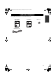
00_MCX-CA15_Owners_UB.book Page 4 Friday, April 30, 2004 10:53 AM CONTROLS AND FUNCTIONS Front panel 1 MCX-CA15 5 AUDIO OUT AUDIO IN IR/CTRL SW OUT VIDEO OUT 6 2 3 DC IN 12V 4 STATUS 7 1 AUDIO OUT jacks 4 STATUS indicator Connect a receiver or amplifier (audio input source) to these jacks. Lights up when this unit is active (receiving a signal). Dims when this unit is in sleep mode. Flashes rapidly when the protection circuitry has been activated or an abnormality occurs.
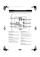
00_MCX-CA15_Owners_UB.book Page 5 Friday, April 30, 2004 10:53 AM CONTROLS AND FUNCTIONS INTRODUCTION Inside front panel A B C 1 MODE 2 RESET INPUT SENSE 3 1 MODE switch Switches between operation modes “A”, “B” and “C” (see page 10). 2 RESET button Resets this unit after the protection circuitry has been activated or the operation mode has been changed (see page 11). 3 INPUT SENSE Detects the presence of signals input through the AUDIO IN jack (see page 11).
00_MCX-CA15_Owners_UB.book Page 6 Friday, April 30, 2004 10:53 AM CONTROLS AND FUNCTIONS Rear panel SPEAKER OUT 4Ω MIN. 1 1 SPEAKER OUT terminals Connect speakers to these jacks using commercially available speaker cables. 2 DC IN/OUT terminals When this unit is connected to a client only, connect the DC power cable to these terminals to supply power to the client. When this unit is connected to the I/O box, use these terminals to receive power from the I/O box.
00_MCX-CA15_Owners_UB.book Page 7 Friday, April 30, 2004 10:53 AM CONTROLS AND FUNCTIONS INTRODUCTION Bottom panel 1 2 AV IN CONTROL MODE A, B : OUT MODE C : IN 1 AV IN jack Connect a client to this jack using the CAT-5 cable (straight) supplied with the client to input signals from the client. 2 CONTROL OUT/IN jack Connect another MCX-CA15 or an external component to this jack to control the power of this unit.
00_MCX-CA15_Owners_UB.book Page 8 Friday, April 30, 2004 10:53 AM OPERATION Operation modes The MCX-CA15 features three different operation modes for user flexibility. Before using the MCX-CA15, you must set the operation mode to either “A”, “B” or “C” depending on your system configuration. CAUTION Be sure to set the operation mode before connecting the MCX-CA15 to a live power source. ■ Operation Modes Mode Usage A mode Use this mode if you want to use the MCX-CA15 as a companion to a client.
00_MCX-CA15_Owners_UB.
00_MCX-CA15_Owners_UB.book Page 10 Friday, April 30, 2004 10:53 AM OPERATION ■ To switch the operation mode You can switch between the operation modes on the MCX-CA15 by sliding the MODE switch located on the inside front panel to the left and right. CAUTION 3 Press RESET using a ballpoint pen or similar object. 4 Replace the front panel by pressing it gently onto the main unit until it clicks into place.
00_MCX-CA15_Owners_UB.book Page 11 Friday, April 30, 2004 10:53 AM OPERATION Input level sensing function In “B” mode, the MCX-CA15 automatically activates (exits sleep mode) when its circuitry senses a signal input from an external source connected to the AUDIO IN jack. RESET button The RESET button is located on the inside front panel. You can use INPUT SENSE to change the detectable signal threshold.
00_MCX-CA15_Owners_UB.book Page 12 Friday, April 30, 2004 10:53 AM TROUBLESHOOTING Refer to the chart below if the MCX-CA15 does not function properly. If the problem you are experiencing is not listed below or if the instruction below does not help, disconnect the power cord, and contact the nearest authorized YAMAHA dealer or service center. Problem Cause Remedy Refer to page The AV link technology function does not work correctly. The signal is weak (for IR flasher connections only).
00_MCX-CA15_Owners_UB.book Page 13 Friday, April 30, 2004 10:53 AM SPECIFICATIONS AUDIO PERFORMANCE • Minimum RMS output power 1 kHz, 1% THD................................................................................................................................................ 13 W + 13 W • Maximum power (EIAJ) 1 kHz, 10% THD......................................................................................................................17 W + 17 W or 18 W (1 ch) • Frequency response (EIAJ) ....
00_MCX-CA15_Owners_UB.
00_MCX-CA15_Owners_UB.
00_MCX-CA15_Owners_UB.book Page 16 Friday, April 30, 2004 10:53 AM © 2004 YAMAHA ELECTRONICS CORPORATION, USA 6660 ORANGETHORPE AVE., BUENA PARK, CALIF. 90620, U.S.A. YAMAHA CANADA MUSIC LTD. 135 MILNER AVE., SCARBOROUGH, ONTARIO M1S 3R1, CANADA YAMAHA ELECTRONIK EUROPA G.m.b.H. SIEMENSSTR. 22-34, 25462 RELLINGEN BEI HAMBURG, F.R. OF GERMANY YAMAHA ELECTRONIQUE FRANCE S.A. RUE AMBROISE CROIZAT BP70 CROISSY-BEAUBOURG 77312 MARNE-LA-VALLEE CEDEX02, FRANCE YAMAHA ELECTRONICS (UK) LTD.