©YAMAHA HTR-6 IP"..
IMPORTANT SAFETY INSTRUCTIONS 10 CAUTION RISK OF ELECTRIC SHOCK 00 NOT OPEN CAUTION: TO REDUCE THE RISK OF ELECTRIC SHOCK, DO NOT REMOVE COVER (OR BACK). NO USER-SERVICEABLE PARTS INSIDE. REFER SERVICING TO OUALIFIED SERVICE PERSONNEL.
IMPORTANT SAFETY INSTRUCTIONS d) 20 21 22 23 If the product does not operate normally by following the operating instructions.
Caution: Read this before operating your unit. 1 To assure the finest performance, please read this manual carefully. Keep it in a safe place for future reference. 2 Install this sound system in a well ventilated, cool, dry, clean place - away from direct sunlight, heat sources, vibration, dust, moisture, and/or cold. Allow ventilation space of at least 30 cm on the top, 20 cm on the left and right, and 20 cm on the back of this unit.
Contents INTRODUCTIO Features...................................................................2 Getting started........................................................3 Quick start guide....................................................4 Preparation; Check the items....................................4 Step 1: Set up your speakers.................................... 5 Step 2; Connect your DVD player and other components..........................................................
Features Built-in 5-channel power amplifier ♦ Minimum RMS output power [U.S.A. and Canada models] (1 kHz, 0.9% THD, 8 Q) Front: lOOW/ch Center: 100 W Surround: lOOW/ch [Other models] (1 kHz, 0.
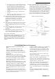
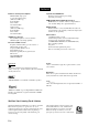
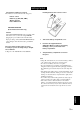
Getting started ■ Checking the supplied accessories Installing batteries in the remote control Check that you received all of the following parts. □ □ □ □ Remote control Batteries (2) (AAA, R03, UM-4) AM loop antenna Indoor FM antenna VOLTAGE SELECTOR (Asia and General models only) Caution The VOLTAGE SELECTOR on the rear panel of this unit must be set for your local voltage BEEORE plugging the power cable into the AC wall outlet.
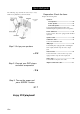
Quick start guide The following steps describe the easiest way to enjoy DVD movie playback in your home theater. Front right Preparation: Check the items Prepare the following items. Surround right speaker □ Speakers □ Front speaker ..............................................x2 □ Center speaker.............................................x1 □ Surround speaker........................................ x2 Select magnetically shielded speakers. The minimum required speakers are two front speakers.
Quick start guide Be sure to connect the left channel (L), right channel (R), “+” (red) and (black) properly. step 1: Set up your speakers Front speakers Place your speakers in the room and connect them to this unit. 1 2 Place your speakers and subwoofer in the room. 0 0 © y Connect speaker cables to each speaker. To the front right speaker To the front left speaker Center and surround speakers Cables are colored or shaped differently, perhaps with a stripe, groove or ridge.
Quick start guide Step 2: Connect your DVD player and other components 3 Connect the video cable to the video input jack on your video monitor and the VIDEO MONITOR OUT jack on this unit. Video monitor ..._____,___ Make sure that this unit and the DVD player are unplugged from the AC wall outlets. 4 Connect the power plug of this unit and other components into the AC wall outlet.
Quick start guide Step 3: Turn on the power and press SCENE 1 button 5 Rotate ©VOLUME to adjust the volume. Check the type of the connected speakers. If the speakers are 6 ohm speakers, set “SP IMP.” to “6QMIN” before using this unit (see page 12). 1 Turn on the video monitor and then set the input source selector of the video monitor to this unit. Note 2 Press ©STANDBY/ON on the front panel.
Quick start guide Notes You must connect a cable TV or a satellite tuner to this unit in advance. See page 16 for details. * - You need to connect the supplied FM and AM antennas to this unit in advance. See page 19 for details. You have to tune into the desired radio station. See pages 37 to 39 for the tuning information. ^'4 To achieve the best possible reception, orient the connected AM loop antenna, or adjust the position of the end of the indoor FM antenna.
Connections Rear panel CDMPONbNI VlUfcO M^rrOR Pn "'W w 9 ■□ DIRITAL ÌNPiTt DVD DTV/CBL DVR MOMTOR nprinin ^ lisi 1^ 1 ^ IB ‘ [±3adc on PM UNBÀL. 1® ® 1® ® DVD " ®® ® "® ® ® DTV/CBL DVR CD (PLAVICM (REC) ® ® ® ® ® ® ® »® ® ® ® ® ® ® ® WOOFER ^ u i~..................
Connections Placing speakers The speaker layout below shows the speaker setting we recommend. You can use it to enjoy CINEMA DSP and multi-channel audio sources. FR 'M ■CSW A SR Front left and right speakers (FL and FR) The front speakers are used for the main source sound plus effect sounds. Place these speakers at an equal distance from the ideal listening position. The distance of each speaker from each side of the video monitor should be the same.
Connections Connecting speakers Be sure to connect the left channel (L), right channel (R), this unit cannot reproduce the input sources accurately. ’ (red) and (black) properly. If the connections are faulty. Caution • • • • Use speakers with the specified impedance shown on the rear panel of this unit. If you are to use 6 ohm speakers, be sure to set “SP IMP.” to “6QMIN” before using this unit (see page 12).
Connections Connecting to the FRONT A terminals ^ Red: positive (+) Biack: negative (-) Setting the speaker impedance (U.S.A. and Canada modeis only) Caution If you are to use 6 ohm speakers, set “SP IMP.” to “6QMIN” as follows BEFORE using this unit. 1 1 Loosen the knob. 2 Insert the bare end of the speaker wire into the slit on the terminal. 3 Make sure this unit is turned off. See page 19 for details about turning on or off this unit. 2 Tighten the knob to secure the wire.
Connections Information on jacks and cable plugs Audio jacks and cable plugs Video jacks and cable plugs COMPONENT VIDEO Y PB PR (Green) (Blue) (Red) tti Pb Composite video cabie plug Pb Component video cabie piugs ■ Audio jacks ■ Video jacks This unit has three types of audio jacks. Connection depends on the availability of audio jacks on your other components. This unit has two types of video jacks. Connection depends on the availability of input jacks on your video monitor.
Connections Information on HOMI™ Audio signals input at the HDMI jack are not output from any speaker terminals but output from the connected video monitor. To enjoy the sound from speakers connected to this unit, -make an analog or digital connection besides the HDMI connection (see page 16). -mute the volume of the connected video monitor. You can play back pictures by connecting your video monitor and video source component to this unit using HDMI connections.
Connections Connecting video components You can also connect a video monitor, DVD player, digital TV, and cable TV to this unit using the HDMI or COMPONENT VIDEO connection (see page 16). Connecting player a video monitor and a Make sure that this unit and other components are unplugged from the AC wall outlets. DVD Connecting a cable and a DVD recorder TV/satellite tuner n E m I Js c a o A < c.
Connections ■ Connecting to the HDMI or COMPONENT VIDEO jacks You can enjoy high-quality pictures by connecting your video monitor and video source components to this unit using HDMI or COMPONENT VIDEO connections. Note Be sure to connect your video components in the same way you connect your video monitor to this unit.
Connections Connecting audio components ■ Connecting a CD player and a CD recorder/MD recorder Make sure that this unit and other components are unplugged from the AC wall outlets. Note When you connect your CD player via analog and digital connection, priority is given to the signal input at the DIGITAL INPUT jack. E-, i; [o Audio out I L |r| i¿ \.
Connections Connecting a Yamaha iPod™ universal dock and Bluetooth™ adapter Connecting to the VIDEO AUX jacks on the front panel Use the VIDI'.O .U’X jticks on the lr
Connections Assembling the supplied AM loop antenna Connecting the FM and AM antennas Both FM and AM indoor antennas are supplied with this unit. In general, these antennas should provide sufficient signal strength. Connect each antenna correctly to the designated terminals. Notes The AM loop antenna should be placed away from this unit. A properly installed outdoor antenna provides clearer reception than an indoor one. If you experience poor reception quality, install an outdoor antenna.
Connections Front panel display © Decoder indicator ® PCM indicator Lights up when any of the decoders of this unit functions. Lights up when this unit is reproducing PCM (Pulse Code Modulation) digital audio signals. @ ENHANCER indicator Lights up when the Compressed Music Enhancer mode is selected (see page 34). ® Headphones indicator @ VIRTUAL indicator ® SP A B indicators Lights up when Virtual CINEMA DSP is active (see page 36).
Connections ■ Using the remote control The remote control transmits a directional infrared ray. Be sure to aim the remote control directly at the remote control sensor on this unit during operation. © Infrared window Outputs infrared control signals. Aim this window at the component you want to operate. To set the remote control codes for other components, see page 53. Notes * • • Do not spill water or other liquids on the remote control. • Do not drop the remote control.
Basic setup The “BASIC SETUP” feature is a useful way to set up your system quickly and with minimal effort. Notes • Make sure you disconnect your headphones from this unit. • If you wish to configure this unit manually using more precise adjustments, use the detailed parameters in "SOUND MENU” (see page 45). • Altering any parameters in "BASIC SETUP” resets all parameters manually adjusted in "SOUND MENU” (see page 45). • Initial settings are indicated in bold under each parameter.
Basic setup 1 Press ©V to select “SET” and then © to select the desired setting. Choices: SET, CANCEL • Select “SET” to apply the settings you made. • Select “CANCEL” to cancel the setup procedure without making any changes. 10 Press ©ENTER to confirm your selection. • If you selected “YES” in step 9, the setup procedure is completed and the display returns to the top set menu display. Press ©MENU to exit from “BASIC SETUP”.
Selecting the SCENE templates This unit is equipped with 13 preset SCENE templates for various situations of using this unit. As the initial factory setting, the following SCENE templates are assigned to each SCENE button: 2 Press (n)INPUT <1/o (or press 0AMP and then ©
Selecting the SCENE templates Which SCENE template would you like to select? Which source do you like to play back? Video sources (DVD video, Recorded video) Which component do you like for playback? DVD SCENE templates Default SCENE buttons DVD Viewing DVD Movie Viewing DVD Live Viewing Music discs (CD, SA-CD or DVD-Audio) DVD Music Disc Listening Disc Listening CD CD Listening CD Music Listening Radio programs TUNER (FM/AM) Radio Listening iPod or Bluetooth component DOCK Dock Listenin
Selecting the SCENE templates Preset SCENE template descriptions SCENE template CD Music Listening Features Input source Playback mode Select this SCENE template when you play back music discs on your CD player. CD 2ch Stereo DVD Viewing (SCENE 1 as the default setting) Select this SCENE template when you play back general contents on your DVD player. DVD STRAIGHT Radio Listening (SCENE 4 as the default setting) Select this SCENE template when you enjoy EM or AM radio programs.
Selecting the SCENE templates Creating your original SCENE templates You can create your original SCENE templates for each SCENE button. You can refer to the preset 13 SCENE templates to create the original SCENE templates. ■ Customizing the preset SCENE templates Use this feature to customize the preset SCENE templates.
Selecting the SCENE templates Using remote control on the SCENE feature ■ Controlling the input source components in the SCENE mode ■ Setting input source of the customized SCENE template on the remote control You can operate both this unit and the input source component by using the remote control. You must set the appropriate remote control code for each input source in advance (see page 53).
Playback Caution Extreme caution should be exercised when you play back CDs encoded in DTS. If you play back a CD encoded in DTS on a DTS-incompatible CD player, you will only hear some unwanted noise that may damage your speakers. Check whether your CD player supports CDs encoded in DTS. Also, check the sound output level of your CD player before you play back a CD encoded in DTS. Basic operations 1 Rotate ©VOLUME (or press ©VOLUME +/-) to adjust the volume to the desired output level.
Playback ■ Selecting the front speaker set Additional operations Using your headphones Connect a pair of headphones with a stereo analog audio cable plug to the PHONES jack on the front panel. Press QSPEAKERS repeatedly to turn on or off the set of front speakers connected to the FRONT A or FRONT B speaker terminals. The active front speaker set changes as follows: FRONT A -> FRONT B OFF f- Note rrzij I! Turn off the volume level of this unit when you switch the front speaker setting.
Playback ■ Selecting audio input jacks (AUDIO SELECT) This unit comes with a variety of input jacks. Use this feature (audio input jack select) to switch the input jack assigned to an input source when more than one jacks are assigned to an input source. • We recommend setting audio input jack select to “AUTO” in most ca,ses. • You can adjust the default audio input jack select of this unit by using “AUDIO SELECT” in “OPTION MENU” (see page 50).
Playback ■ Adjusting speaker levels during playback You can adjust the output level of each speaker while listening to a music source. ■ Displaying the signal information You can display the format, sampling frequency, channel, bit rate and flag data of the current input signal. 1 Press ©AMP and then press ©MENU on Note the remote control. This operation will override the level adjustment made in "SP LEVEL” (see page 46). “BASIC SETUP” appears in the front panel display.
Playback ■ Using the sleep timer Use this feature to automatically set this unit to the standby mode after a certain amount of time. Press 0AMP and then press ©SLEEP repeatedly to set the amount of time. Each time you press ©SLEEP, the front panel display changes as shown below. ■ Playing video sources in the background You can combine a video image from a video source with sound from an audio source.
Sound field programs This unit is equipped with a variety of precise digital decoders that allow you to enjoy multi-channel playback from almost any stereo or multi-channel sound source. Press® PROGRAM <1 /[> (or press ® AMP and then press ® PROG <1/0 repeatedly). The name of the selected sound field program appears in the front panel display. Notes • When you select an input source, this unit automatically selects the last sound field program used with the corresponding input source.
Sound field programs ■ Selecting decoders for 2-channel sources (surround decode mode) Initial settings are indicated in bold under each parameter. Signals input from 2-channel sources can also be played back on multi-channels. For Pop/Rock, Hall, Jazz, Game, TV Sports, Movie Spacious and Movie Dramatic: Press 0AMP and then press @SUR. DECODE repeatedly to select a decoder. You can select from the following decoders depending on the type of source you are playing and your personal preference.
Sound field programs ■ Using sound field programs without surround speakers (Virtual CINEMA DSP) Virtual CINEMA DSP allows you to enjoy the CINEMA DSP programs without surround speakers by creating virtual speakers. If you set “SUR. LR” to “NONE” (see page 47), Virtual CINEMA DSP is automatically activated whenever you select a sound field program (see page 34). Note Vii tual CINEMA DSP will not be activated even when “SUR.
FM/AM tuning There are 2 tuning methods: automatic and manual. Automatic tuning is effective when station signals are strong and there is no interference. If the signal from the station you want to select is weak, tune into it manually. You can also use ihe aulomalic and manual preset tuning features to store up to 40 stations. Automatic tuning Manual tuning Automatic tuning is effective when station signals are strong and there is no interference.
FM/AM tuning Automatic preset tuning Manuai preset tuning You can use the automatic preset tuning feature to store FM stations with strong signals up to 40 (A1 to E8: 8 preset station numbers in each of the 5 preset station groups) of those stations in order. You can then recall any preset station easily by selecting the preset station number. You can also store up to 40 stations (AI to E8: 8 preset station numbers in each of the 5 preset station groups) manually.
FM/AM tuning Selecting preset stations Exchanging preset stations You can tune into any desired station simply by selecting the preset station group and number under which it was stored. You can exchange the assignments of two preset stations with each other. The example below describes the procedure to exchange preset station “El” with “A5”. When performing this operation with the remote control, press ©TUNER to select 'TUNER” as the input source.
Using iPod™ Once you have stationed your iPod in a Yamaha iPod universal dock (such as the YDS-10, sold separately) connected to the DOCK terminal of this unit (see page 18), you can enjoy playback of your iPod using the supplied remote control. Supported iPod iPod (Click and Wheel) iPod nano iPod mini Battery charge feature Your iPod battery is automatically charged when your iPod is stationed in a Yamaha iPod universal dock connected to the DOCK terminal of this unit as long as this unit is turned on.
Using Bluetooth™ components You can connect a Yamaha Bluetooth adapter (such as YBA-IO, sold separately) to the DOCK terminal of this unit and enjoy the music contents stored in your Bluetooth component (such as a portable music player) without wiring between this unit and the Bluetooth component. You need to perform “pairing” the connected Bluetooth adapter and your Bluetooth component in advance.
Recording Recording adjustments and other operations are performed from the recording components. Refer to the operating instructions for those components. Notes • When this unit is set to the standby mode, you cannot record between other components connected to this unit. • The settings of TONE CONTROL (see page 31) and VOLUME settings, speaker levels (see page 32) and the sound field programs (see page 34) do not affect recorded material.
Set menu You can use the following parameters in set menu to adjust a variety of system settings and customize the way this unit operates. Change the initial settings (indicated in bold under each parameter) to reflect the needs of your listening environment. ■ Basic setup Use this feature to automatically adjust speaker and system parameters (see page 22). ■ Manual setup Use this feature to manually adjust speaker and system parameters.
1 Set menu 1 Option menu Use this menu to manually adjust the optional system parameters. Parameter Features Page Adjusts the brightness of the front panel display. 50 Locks sound field program parameters and other set menu settings. 50 C)HUDIU SELECT Designates the default audio input jack select setting mode for the input sources connected to the DIGITAL INPUT jacks when you turn on the power of this unit.
1 SOUND MENU Use this menu to manually adjust any speaker settings or compensate for video signal processing delays when using LCD monitors or projectors. Woofer section of a speaker i s 16 cm (6..5 in) or larger: large Woofer section of a speaker i s smaller than 16 cm ( 6 .5 in): small Front speakers ■ Speaker settings Use this feature to manually adjust any speaker settings.
LFE/Bass out ■ Speaker level Use this feature to select the speakers that output the LFE (low-frequency effect) and the low-frequency signals. Choices: SWFR, FRNT, BOTH Use this feature to manually adjust the output level of each speaker. Control range: -10 to -l-lO dB Control step: 1 dB Initial setting: 0 dB If you are not satisfied with the bass sounds from your speakers, you can change these settings according to your preference.
■ Speaker distance Use this feature to manually adjust the distance ot each speaker and the delay applied to the respective channel. Ideally, each speaker should be the same distance from the main listening position. However, this is not possible in most home situations. Thus, a certain amount of delay must be applied to the sound from each speaker so that all sounds will arrive at the listening position at the same time. Unit UNIT Choices: meters (m), feet (ft) Initial setting: [U.S.A.
■ Audio settings Use this feature to adjust the o\eiall audio settings of this unit. Mute type Use this feature to adjust how much the mute function reduces the output volume (see page 30). Choices: FULL, -20dB • Select “FULL” to completely mute all the audio output. • Select “-20dB” to reduce the current volume by 20 dB. Audio delay Use this feature to delay the sound output and synchronize it with the video image. This may be necessary when using certain LCD monitors or projectors.
■ Input rename ■ Use this feature to change the name of the input source that appears in the front panel display. Use this feature to adjust the le\el of the signal input at each jack. This is useful if you want to balance the level of each input source to avoid sudden changes in volume when switching between input sources. The following is an example where “DVD” is renamed “My DVD”.
■ Bluetooth setting 3 OPTION MENU Start pairing :: Use this menu to adjust the optional system parameters. ■ Display settings Dimmer Use this feature to adjust the brightness of the front panel display. Control range:-4 to 0 Control step: 1 • Press © to make the front panel display brighter. ■ l :: :: : : Use this feature to prevent accidental changes to DSP program parameter values and other system settings.
Remote control features In addition to controlling this unit, the remote control can also operate other audiovisual components made by Yamaha and other manufacturers. To control your TV or other components, you must set up the appropriate remote control code for each input source (see page 53). Controlling this unit, a TV, or other components ■ Controlling this unit Press 0AMP to control this unit. ■ Controlling a TV Press (DDTV/CBL to control your TV.
Remote control features ■ Controlling other components Press one of the input selector buttons (@) or A to E buttons to control othercomponents. You must set the appropriate remote control code for each input source in advance (see page 53). The following table shows the function of each control button used to control other components assigned to each input selector button. Be advised that some buttons may not correctly operate the selected component.
Remote control features Setting remote control codes You can control other components by setting the appropriate remote control codes. For a complete list of available remote control codes, refer to “List of remote control codes” at the end of this manual. Press the numeric buttons (0 to 9) (@) to enter the four-digit remote control code for the component to be used. When the setting succeeds, “RemoteSetup OK” appears; however, when it dues not, “RemoteSetup NG” appears in the front panel display.
Advanced setup This unit has additional menus that are displayed in the front panel display. The advanced setup menu offers additional operations to adjust and customize the way this unit operates. Change the initial settings (indicated in bold under each parameter) to reflect the needs of your listening environment. ■ Speaker impedance (U.S.A. and Canada models only) Use this feature to set the speaker impedance of this unit so that it matches that of your speakers.
Troubleshooting Refer to the table below when this unit does not function properly. If the problem you are experiencing is not listed below or if the instruction below does not help, turn off this unit, disconnect the power cable, and contact the nearest authorized Yamaha dealer or service center. ■ General Problem This unit faiis to turn on or enters the standby mode soon after the power is turned on. No sound The sound suddeniy goes off. Sound is heard from the speaker on one side oniy.
\ Troubleshooting \ Problem Cause Remedy See page Only the center speaker outputs substantial sound. When playing a monaural source with a CINEMA DSP program, the source signal is directed to the center channel, and the front and surround speakers output effect sounds. No sound is heard from the center speaker. “CENTER” in “SPEAKER SET” is set to “NONE”. Set “CENTER” to “SML” or “ERG”. 45 Some sound field programs do not output sounds from the center speaker. Try another sound field program.
Troubleshooting Problem Cause Remedy There is noise interference from digitai or radio frequency equipment. This unit is too close to the digital or high-frequency equipment. The picture is disturbed. The video source uses scrambled or encoded signals to prevent dubbing. This unit suddeniy enters the standby mode. The internal temperature is too high and the overheat protection circuitry has been activated. See page Move this unit further away from such equipment.
Troubleshooting ■ iPod Note In case of a transmission error without a status message appearing in page 18). Stntus messnge Connect ennon the front panel display, check the connection to your iPod (see Cause There is a problem with the signal path from your iPod to this unit. UnlonOWn Ih'Od The iPod being used is not supported by this unit.
I Troubleshooting I ■ Remote control Problem The remote control does not work nor function properly. Cause Remedy See page W roiig ylislaiicc or angle. file reniole eonlrol fiinelioii'' williiii a ma.xinuim range of 6 m (20 ft) and no more than 30 degrees off-axis from the front panel. Direct sunlight or lighting (from an inverter type of fluorescent lamp, etc.) is striking the remote control sensor of this unit. Reposition this unit. The batteries are weak. Replace all batteries.
Glossary ■ Audio information Dolby Digital Dolby Digital is a digital surround sound system that gives you completely independent multi-channel audio. With 3 front channels (front L/R and center), and 2 surround stereo channels, Dolby Digital provides 5 full-range audio channels. With an additional channel especially for bass effects, called LFE (Low Frequency Effect), the system has a total of 5.1 -channels (LFE is counted as 0.1 channel).
Glossary ■ Sound field program information Video information CINEMA DSP Component video signal Since the Dolby Surround and DTS systems were originally designed for use in movie theaters, their effect is best felt in a theater having many speakers designed for acoustic effects. Since home conditions, such as room size, wall material, number of speakers, and so on, can differ so widely, it is inevitable that there are differences in the sound heard.
Specifications AUDIO SECTION VIDEO SECTION • Miniiniiin RMS Output Power for Front, Center, Surround [U.S.A. and Canada models] 1 kHz, 0.9% THD, 8 Q ............................................ 100 W/ch [Other models] 1 kHz, 0.9% THD, 6 Q ............................................... 100 W/ch • Signal Level Composite.................................................................. 1 Vp-p/75 Q Component ................... 1 Vp-p/75 Q (Y), 0.7 Vp-p/75 Q (Pb/Pr) • Maximum Power (JEITA) [U.S.A.
■ Numerics 1 SOUND MENU .............................. 43,45 2 INPUT MENU ................................ 43,48 2ch Stereo .................................................34 3 OPTION MENU .............................. 4450 5ch Stereo .................................................34 ■ A A)DTSPLAYSET .................................... 50 A)TNPUT ASSIGN ................................. 48 A)SPEAKERSET .....................................45 A.DEEAY ................................................
Input source indicators ............................20 Input source information..........................32 Installing batteries in the remote control .......................................3 iPod connected, iPod controlling status message........... 58 iPod control, Status message .................. 58 ■ J Jazz........................................................... 34 ■ L LFE indicator ...........................................20 LFE/Bass out............................................
Front panel (B) (C) F) (G) (H ©YAfiiAHA 43/ vv r* > r.
Remote control
List of remote control codes Blu-ray player Samsung 2137 CD player Yamaha 5000. 5013 CD Recorder Yamaha 5001 DVD Acouslic Solutions 2078 Aiwa 2055. 2100 Akai 2096 Akura 2076 2078.2086 Alba Apex 2027,2049 2078 Awa Axioii 2078 Brainwave 2096 Brandt 2073,2085 Broksoilic 2060 Bush 2075.2078,2112 Cciitrcx 2077 2078 Classic Clalronic 2075 2078 Cohy C-Tcch 2074 CyberHome 2025,2079,2091 Daewoo 2092.2098 Dansai 2096 Daytek 2080.2089 DEC 2075 Deiion 2030.2102, 2103 Denver 2075.
Akai Akiba Akura Alaroii Alba ALBIRAL Alisi ar Amplivision Amstrad 0059. 0065.0127. 0129.0130. 0200. 0204. 0208. 0209. 0213.0217. 0218. 0255 0209.0218 0206. 0209.0218 0200 0200. 0207. 0208. 0209,0217. 0218 0212 0213 0207 0204. 0206. 0208. 0209,0218 Amlroii 0062 0208 Anam Anam National 0062 0208 Anglo Anilcch 0206.0208 Ausonie 0203.0208 AOC 0060.0061 Apex 0118.0122. 0132 Arc cn Ciel 0216 Arcam 0200 Arcam Della 0207 Aristona 0213.0217 ASA 0205.0211 Asberg 0213 0208 Astra Asuka 0200. 0206. 0207. 0209.
()208 0207. 0208 0214 0206, 0213,0217 0016. 0038,0039. 0127,0128. 0157. 0158,0163.0164. 0166, 0188, 0189. 0200, 0201.0207. 0208,0210. 0213. 0214. 0215.0217 Lieseiik 0217 Life 0206, 0208 Lifelec 0206. 0208,0218 Loewe 0063,0128,0203. 0204.0223. 0227 Loewe Opta 0205,0213.0217 Logik 0058 Luma 0210,0217 Lumatron 0210, 0213.0217 0213 Lux May Luxman 0060. 0061 Luxor 0201.0207.0210 LXI 0057,0061.0063. 0064 Magnadyne 0204. 0205.0214. 0215,0217 Magiiafoii 0200, 0204. 0207 Magnavox 0060. 0061,0063. 0102, 0103.
Tandy Tashiko Tatung тем Тсае Тсс Tcchwood Teknika Tclcavia Tclccor Tclclunkcn Tclcgazi Tclclcch Tclclon Tclcvidcon Tensai Tcsmcl Tevion Texet Thomson Thorn TMK Tokai Tokyo Toshiba Towada Translcc Trident Tristar Triumph Uher Ultravox United UnivcrsLim Univox Vestel 0127.0207.0209. 0211.0218 0200. 0207.0210 0127.0204. 0207. 0213,0217. 0237 0206.0208 0127 0207.0208.0214. 0215 0060.0061 0058.0060. 0061. 0062 0216 0218 0065.0213.0216 0218 0208.0214. 0217 0207 Wcllblick 0213.
Mcmorcx lOOE 1002.1003. 1004. 1013. 1045. Memphis 1050 1048 Mclz MGA 1014 MGN Technology 1002. Micromaxx 1044, Microstar 1044. Migros 1042 Minolta 1010 Mitsubishi 1011. MontgomeryWard 1008 Motorola 1004, MTC 1002, Miiltitech 1002, 1042, Murphy 1042 National 1048 NEC 1000, 1011. Neckennann 1043, NEI 1046 Nesco 1050 Nikko 1003 Nohlex 1002. Nokia 1043. Nordmende 1043 Oceanic 1042, 1044 Oka no Olympus 1004 Optimus 1003, Orion 1012. 1065 Orson 1042 Osaki 1042, Otto Versand 1046 Palladium 1043, Panasonic 1004.
II #YAMAHA HTR-6130 The circled numbers and alphabets correspond to those in the Owner’s Manual. Les nombres et lettres dans un cercle correspondent à ceux du mode d’emploi.
Remote control/Boîtier de télécommande PRINTED WITH SOYINK YAMAHA CORPORATION Printed in China c WN26290