Safety ° Assembly ° Operation ° Adjustments ° Maintenance O P RA-rO R'S ° Troubleshooting ° Parts Lists ° Warranty MANUAL Two-Stage Snow Thrower IMPORTANT READ SAFETY RULES AND INSTRUCTIONS CAREFULLY BEFORE OPERATION Warning: This unit is equippedwithan internalcombustionengineand shouldnot be usedon or nearany unimprovedforest-covered,brushcoveredor grass-coveredland unlesstheengine'sexhaustsystemis equippedwith a sparkattester meetingapplicablelocalor statelaws(if any), If a sparkarresteris use
This Operator's Manual is an important part of your new snow thrower. It will help you assemble, prepare and maintain the unit for best performance. Please read and understand what it says. Table of Contents Safety Labels ...................................................... 3 Safe Operation Practices ................................... 4 Setting Up Your Snow Thrower .......................... 6 Operating Your Snow Thrower ......................... 10 MakingAdjustments ....................................
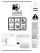
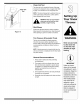
WARNING STOP CS00071 This symbol points out important safety instructions which, if not followed,could endangerthe personal safety and/or propertyof yourself and others. Read and follow all instructions in this manual before attemptingto operate this machine. Failure A chute clean-out tool is fastened to the top of the auger housingwith a mounting clip. The tool is designed to clear a chute assembly of ice and snow. This item is fastened with a cable tie at the ChuteClean-out Tool factory.
WARNING: Engine Exhaust, some of its constituents, and certain vehicle components contain or emit chemicals known to State of Californiato cause cancer and birth defects or other reproductiveharm. DANGER: This machine was built to be operated according to the rules for safe operation in this manual. As with any type of power equipment, carelessness or error on the part of the operator can result in serious injury. This machine is capable of amputating hands and feet and throwing objects.
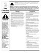
Operation Maintenance 1. Donot put hands or feet near rotatingparts, inthe auger/impellerhousingor chuteassembly.Contactwiththe rotatingparts can amputatehands andfeet. 2. The auger/impellercontrolleveris a safetydevice.Never bypassits operation.Doingso makesthe machineunsafe and may causepersonalinjury. 3. The controlleversmustoperate easilyin bothdirections and automaticallyreturnto the disengagedpositionwhen released. & Storage 1. Nevertamper withsafetydevices.Checktheir proper operationregularly. 2.
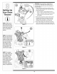
IMPORTANT:The snowthroweris shippedwith oil and WITHOUTGASOLINE.After assembly,referto separateenginemanualfor properfueland engineoil recommendations. 1. Observethe lowerarea of the snowthrowerto be surebothcables are alignedwith roller guidesbefore pivotinghandleupward, a. Pull up and backon upperhandleas shownin Figure1.Align upper handlewith the lowerhandle, b. Tightenhandknobs securingupperhandleto lowerhandle, 2.
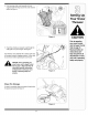
4, Finishsecuringchute controlassemblyto chute support bracketwith wingnut and hexscrew removed earlier,See Figure4, Figure 4 Prior to operating your snow thrower, refer to Auger Control Test on page 13.
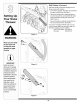
Drift Cutters i (If Equipped) Driftcutters shouldbe usedwhenoperatingthe snow throwerin heavy drift conditions, • On modelsso equipped,drift cuttersare assembledto the augerhousinginverted,See Figure7, • Removethecarriagebolts by unthreadingthe hex nuts whichsecurethem,and reinstallthe drift cutters facingforwardbeforeoperatingthe snow thrower.
Clean-Out Tool Theclean-outtool is mountedto the rear of the auger housingand is designedto cleara cloggedchute.Refer to page 11for instructionson howto properlyuseit. Clean-Out Tool NOTE: This itemis fastenedwith a cabletie to the rear of the augerhousingat the factory.Cutthe cabletie beforeoperatingthe snowthrower. g Your Snow clean snowand ice fromthe chute WARNING:Neveruseyour handsto assemblyor augerhousing. ,_ Skid Shoes Positionthe skid shoesbasedon surfaceconditions.
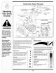
Know Your Snow Thrower f Drive Control .Shift Lever Four-Way Chute ControFM HeatedHandles Jger Control Switch (en option)lHeadlig Wheel Steering Control Electric Start Gas Ca Oil EngineControls RecoilStarter Handle ElectricStarter Outlet Primer Ignition Key WARNING Read, understand, and follow all instrucLionsand warnings on the machine and in this manual before Choke Control Clean-Out tool 1 If Equipped Throttle Control J operating. Figure 11 Use extreme care when handling gasoline.
• Tochangethe directionin which snowis thrown, squeezethe buttonon thejoy-stickand pivot the joy-stickto the rightor to the left. Auger Control f AUGER CONTROL • Tochangethe angle/distancewhich snow isthrown, pivotthejoy-stickforwardor backward. Wheel Steering Controls The left and rightwheelsteeringcontrolsare locatedon the undersideof the handles.Squeezethe rightcontrolto turn right; squeezethe left control to turnleft.
Gas & Oil Fill-Up Servicethe enginewith gasolineand oil as instructedin the separateenginemanualpackedwith your unit, Read instructionscarefully. !iii i iii i ii!i/Starting iiii WARNING 7, Whendisconnectingtheextensioncord, always unplugtheend at thethree-prongwalloutlet before unpluggingthe oppositeend from the snowthrower. Recoil Starter The Engine 1, Attachsparkplug wireto sparkplug.
2. Ina well-ventilatedarea,startthe snowthrower engineas instructedon the previouspage.Make sure the throttleis set in the FASTposition. NOTE: Keepthe keyin a safe place.Theengine cannot startwithoutthe ignitionkey. Recoil Starter 3. Whilestandingin theoperator'sposition(behindthe snowthrower),engagethe auger. 1. With enginerunning,pull starter ropewith a rapid, continuousfull arm strokethreeor fourtimes. Pulling the starterropewill producea loud clatteringsound, which is notharmfulto engine. 4.
Shift Cable If the full rangeof speeds(forwardand reverse)cannot be achieved,referto the figureto the left and adjustthe shiftcable as follows: 1, Placethe shiftleverin the fastest forwardspeed position, 2, Loosenthe hex nuton the shiftcable indexbracket, See Figure13. /// 3. Pivotthe bracketdownwardto take up slack in the cable, 4, Retightenthe hex nut, 5. Checkforcorrectadjustmentbeforeoperatingthe snowthrower.
2. With the drivecontrol released,there mustbe 1/8" clearancebetweenthe frictionwheeland the drive pulleyin all positionsof theshift lever. 3. With the drivecontrolengaged,the frictionwheelmust contactthe drive pulley.Referto Figure28 on page 18. 4. If adjustmentis necessary,loosenthe lowerhexnut on thedrive cableindexbracketand pivot the bracket upwardor downwardas necessary.Referto Figure15. Tightenthe lowerhexnut to securethe bracketwhen correctadjustmentis reached. 5.
,_ glassesduringoperationor while WARNING:Alwayswearsafety performinganyadjustmentsor repairs. Engine Referto the separateengine manualpackedwith your unitfor all enginemaintenance. Lubrication Gear (Hex) Shaft Oncea season,lubricatethe hexshaftwith a penetrating oil, but notgrease. Referto Figure17. Wheels At leastonce a season,removeboth wheels.Cleanand coat theaxles with a multipurposeautomotivegrease beforereinstallingwheels.
Auger Belt Replacement ! To removeand replaceyoursnow thrower'sauger belt, proceedas follows: 1. Removethe plasticbelt coveron the front of the engineby removingthe two self-tappingscrews. NOTE: Drainthe gasolinefrom the snowthrower,or placea pieceof plasticunderthe gas cap. ,J Figure 19 2. Carefullypivotthe snowthrowerup and forwardso that it restson the augerhousing.Removethe frame coverfrom the undersideof the snow throwerby removingfour self-tappingscrewswhich secureit. 3.
Augers . ;now Theaugersare securedto the spiralshaftwith two shearpinsand cotterpins, If the augershouldstrike a foreignobject or icejam, the snowthroweris designedso that the pinsmay shear, I Pin Spacers Bearing • If the augerswill notturn, checkto seeif the pins havesheared,One set of replacementshearpins hasbeen providedwith the snowthrower.
Friction Wheel Removal If the snowthrowerfails to drivewith the drivecontrol engaged,and performingthedrivecontrol cableadjustmenton page 12fails to correctthe problem,the friction wheelmay needto be replaced.Followthe instructions below.Examinethe frictionwheelfor signsof wearor crackingand replaceif necessary. • Placethe shiftleverin third Forward(F3) position. • Drainthe gasolinefrom the snowthrower,or placea pieceof plasticunderthe gas cap.
Observethe following,whenpreparingyoursnow thrower for off-seasonstorage: * Drainfuelinto an approvedcontaineroutdoors,away from any openflame.Allowengineto cool. Extinguish cigarettes,cigars,pipesand othersourcesof ignition priorto drainingfuel. Fuelleft in engineduring warm weatherdeterioratesand will causeseriousstarting problems. * If unitis to be storedover30 days,preparefor storage as instructedin the separateenginemanualpacked with yourunit.
Problem Ca use Enain e failsto sa t rt ChokenotnONposton Remedy : Move choketo ON post on 2. Sparkplugwire disconnected, 2. Connectwire to spark plug. 3 Fueltank emptyorStalefuel. 31 Fi!!tank with clean,fresh gasoiinel 5 Engine not primed, 41 ,Primeengineas instructedin OpeiatingYourSnowTh[owe[ Faulty sparkplug 5. Clean, adjust gap,or replace. &Blocked fUel linel 6. Clean fuel line, 7: Safetykey notin ignitionon enginel 7_Insert keyfu!lyinto the switch.
MANUFACTURER'S LIMITED WARRANTY The limitedwarrantyset forth belowis givenby MTDLLCwith respect to newmerchandisepurchasedand usedin the UnitedStatesand/or its territoriesand possessions,and by MTDProductsLimitedwith respectto newmerchandisepurchasedand usedin Canadaand/or its territoriesand possessions(eitherentity respectively,"MTD").
31AH5GLG 31AH5KLH 634-04145 634-04146 16 x 4.8 x 8 LH X-Trac 16 x 4.8 x 8 RH X-Trac 734-2038 734-2038 634-04173 634-04173 738-041 80 31AH6GLF 31AH6KLG 31AH6GLN 634-04145 634-04146 16 x 4.8 x 8 LH X-Trac 16 x 4.8 x 8 RH X-Trac 734-2038 734-2038 634-04173 634-04173 738-041 80 31AH5MLH 31AH51Q4 31AH5M LH 634-04136 634-04137 16 x 6.5 x 8 LH X-Trac 16 x 6.5 x 8 RH X-Trac 734-2031 734-2031 634-04174 634-04174 738-041 80 738-041 80 31BE6M LO 634-04136 634-04137 16 x 6.5 x 8 LH X-Trac 16 x 6.
\ / / ,_4_ \ 24 _J
REF PART NO. N ° DE NO. N° DE REF PIECE DESCRIPTION DESCRIPTION 1 2 710-1652 731-05353 Hex Wash Hd TT Scr. Belt Cover 1/4-20 x .625 Vis taraudee 1/4-20 x 0,625 Couvre-courroie 3 4 732-0708 711-1268B Cable Control Wire Drive Shaft Actuator 5 6 746-04229 732-0209 7 8 790-00207 684-04156 Drive Clutch Cable 44.83" Lg. Extension Spring .47 OD x 2.
\ jr 1 141 36 40 J 4 16 43 J 22 14 "12 21 %. 9 NOTE:Housing may not be exactly as shown. REMARQUE' L'habitacle peut _tre legerement different.
REF NO. N° DE RI_F 1 2 3 4 5 6 7 8 9 10 11 12 13 14 15 16 17 18 19 20 21 22 23 24 25 26 27 28 29 30 31 32 33 34 35 36 37 38 39 40 41 42 43 44 45 46 47 48 49 5O 51 52 53 54 55 56 57 58 59 6O 61 62 63 64 65 66 PART NO.
Model Numero StylesH, K, L, P & Q Number/ de modele 31AE6GKF500 * With heated grips only/Avec poignees chauffees seulement.
REF NO. N° DE REF 1 1 1 2 3 4 5 6 7 8 9 10 11 12 13 14 15 16 17 18 19 19 20 21 22 23 24 25 26 27 28 29 30 31 32 33 34 35 36 37 38 39 40 42 41 43 44 45 46 47 48 49 51 51 52 52 53 54 55 56 57 58 59 60 65 66 PART NO.
28 \ 4 \ 15\ 15 13 j 16 6 / 21 2 Way Chute Control/ Commande de la goulotte & 2 fonctions REF NO. N°DE R_:F 1 2 3 4 5 6 7 8 9 10 11 12 13 14 15 16 17 18 19 20 21 22 23 24 25 26 27 28 29 30 4 Way Chute Control/ Commande de la goulotte & 4 fonctions PART NO.