
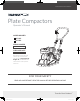
Operating Guide


M5 × 1
1
M10 × 70 × 2
8
Plate Compactor
»
Operator’s Manual
YC1160PM01 - 1703
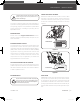
This plate compactor was partially assembled at the factory. To assemble your machine follow the below instructions.
ASSEMBLY
HANDLE
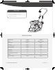
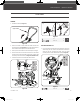
FOLDING WHEELS KIT
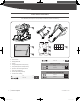
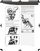
1. Unfold the handle. (See Figure 2a)
1. Line up the holes in the link plates and engine deck. Secure the
wheels using the nuts, washers, and bolts found in hardware
packet #2. Do not overtighten the bolts, leave the wheel
assembly so that it can be released with ease. (See Figure 3a)
2. Mount the handle as shown. Slide the handle ends into the
engine deck slots. (See Figure 2b). Secure with the at washers,
nuts and bolts found in packet #1 of the hardware kit.
3. Unwrap the throttle cable from around the top of the engine.
4. Unscrew bolt 5×35 from throttle control. Secure the throttle
control onto the upper handle with a at washer 5 and the bolt
5×35 that just were unscrewed. (See Figure 2c, illustration 1 & 2)
5. Fasten the throttle control cable with cable fasteners.
Figure 2a
Figure 2b
Figure 2c
Figure 3a
M10 × 30 × 2
2
1 2
M5 (×1)
M10 × 70 (×2)
Lower Handle
1 2
M5 (×1)
M10 × 70 (×2)
Lower Handle
Mounting Holes
M10 × 30 (×2)
Upper Handle
16
mm
15
mm
16
mm
15
mm
17
mm
18
mm
30
mm
13
mm
11
mm
16
mm
15
mm
29142US25M101.indd 8 2017/3/20 13:53:13