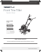
Save This Manual for Future Reference Front Tine Tiller Operator’s Manual MODEL NUMBER YT5328 SERIAL NUMBER PURCHASE DATE Both model number and serial number may be found on the main label (see Page 2, Figure 1). You should record both of them in a safe place for future use.
Your new YARDMAX ® front tine tiller offers quality construction, and is easy and safe to operate. With proper use and care, it is designed to give you many years of dependable service.
Front Tine Tiller » Operator’s Manual MODEL AND SERIAL NUMBERS Carefully read through this entire operator's manual before using your new unit. Pay attention to all cautions and warnings. This machine is a gasoline engine driven front tine tiller. It is a durable, versatile and efficient machine, and it is both easy and safe to operate. With proper use and care, it should give you many years of dependable service.
SUPPORT Have questions about your YARDMAX equipment? Call us at 847-327-0566 or 844-YARDMAX, email us at support@yardmax.com, or contact us via your favorite social media site. SPECIFICATIONS Model Number Engine LCT Displacement 98 cc Torque (ft-lbs, gross) 3.
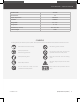
Front Tine Tiller Model Number YT5328 Tine Diameter 11" Depth Adjustments » Operator’s Manual 4 Positions Tine RPM 180 RPM Tilling Width 11" – 21" Tilling Depth 7" – 11" Dimensions (L × W × H) 48" × 24" × 40" Product Weight 95 lbs SYMBOLS The rating plate on your machine may show symbols. These represent important information about the product or instructions on its use. Read these instructions carefully. No smoking, sparks, or flames. Wear eye protection.
SAFETY GENERAL SAFETY RULES UNDERSTAND YOUR MACHINE Read this manual and labels affixed to the machine to understand its limitations and potential hazards. Be thoroughly familiar with the controls and their proper operation. Know how to stop the machine and disengage the controls quickly. Make sure to read and understand all the instructions and safety precautions as outlined in the Engine Manufacturer’s manual packed separately with your unit.
Front Tine Tiller Do not tamper with the engine in an effort to get it to run at higher speeds. The maximum engine speed is preset by the manufacturer and is within safety limits. See engine manual. Keep a Class B fire extinguisher on hand when operating this machine in dry areas as a precautionary measure. FUEL SAFETY Fuel is highly flammable, and its vapors can explode if ignited. Take precautions when using to reduce the chance of serious personal injury.
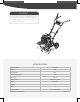
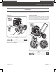
CONTENTS SUPPLIED Your YARDMAX front tine tiller comes partially assembled and contains the following: 10 1 2 3 4 5 7 11 8 12 9 13 HARDWARE KIT 6 Premium 4-Cycle 14 15 NET CONTENTS 8.45 OZ (0.25 L) 1. Upper Handlebar 2. Main Machine 15. Hardware Kit, Including: 1 M10 × 50 ×2 M8 × 45 ×2 M8 × 25 ×2 6. Outer Tine - Left M8 × 25 ×4 3 7. Lower Handlebar M8 × 25 ×2 4 M6 × 16 ×6 5 8 × 45 ×2 3. Outer Tine - Right 4. Inner Tine - Right 5. Inner Tine - Left 8.
Front Tine Tiller » Operator’s Manual ASSEMBLY This front tine tiller was partially assembled at the factory. To assemble your machine follow the below instructions. INNER TINE LOWER HANDLEBAR Align the holes in the lower handlebar with the holes in the support bracket. Insert the M8×45 bolts, spring washers, flat washers into the lower holes. Insert M8×25 bolts and screw big washers and M8 nuts from other side. Tighten M8×45 bolts and M8 nuts.
11 mm HANDLEBAR ADJUSTING PLATE Align the two lower holes in each adjusting plate with the holes in the lower handlebar. Insert M8×25 bolts and screw big washer, M8 nuts tightly. (See Figure 4) ×2 13 mm Adjusting Hole Adjusting Hand Knob 11 mm ×2 17 mm2 1 13 mm 18 mm Bolt Hole 17 mm 3 30 mm 18 mm 30 mm Handlebar Adjusting Plate M8×25 (×2) 1 Figure 5a 2 M8 × 25 ×2 4 The upper adjusting hand knobs can be used in one of three hole positions for handlebar height adjustment.
Front Tine Tiller » Operator’s Manual TINE SHIELD DEPTH STAKE Assemble the tine shields using six M6×16 bolts, flat washers, and M6 lock nuts. (See Figure 6) Insert the depth stake into the depth stake holder tube.(See Illustration 1, Figure 8a) Adjust the depth stake into the desired depth of tilling (See Figure 8b), then lock it with 8×32 pin and clevis pin.
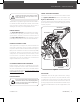
KNOW YOUR MACHINE FEATURES AND CONTROLS Drive Control Lever Handlebar Gas Tank Muffler Air Filter Depth Stake Transport Wheel Tine Shield Inner Tine Outer Tine Choke Control Throttle Control Recoil Starter Handle Engine ON/OFF Switch Oil Tank Cap/Dipstick 11 | Know Your Machine YT5328PM02 - 1807
Front Tine Tiller HANDLEBAR Unscrew this lever, move the handle up or down. Fasten the lever. (See Figure 4b) » Operator’s Manual TINE SHIELD Adjustable to protect small plants from being buried. 3-POSITION ADJUSTABLE HANDLE BARS RECOIL STARTER HANDLE The Recoil Starter Handle is used to start the engine. THROTTLE CONTROL DRIVE CONTROL LEVER Squeeze the lever against the hand grip to engage the tines. Release to disengage tines.
OPERATION ADD OIL TO ENGINE IMPORTANT: DO NOT OVERFILL! This equipment and/or its engine may include evaporative emissions control system components, required to meet EPA and/or CARB regulations, that will only function properly when the fuel tank has been filled to the recommended level. Overfilling may cause permanent damage to evaporative emissions control system components. Filling to the recommended level ensures a vapor gap required to allow for fuel expansion.
Front Tine Tiller 4. Pull the recoil starter until the engine starts. Return the recoil to the home position after each pull. Repeat the steps as needed. Once engine has started, set the throttle to the FAST position before you operate the unit. Rapid retraction of the starter cord (kickback) will pull your handand arm toward the engine faster than you can let go. Broken bones, fractures, bruises, or sprains could result.
MAINTENANCE Maintaining your YARDMAX front tine tiller will ensure long life to the machine and its components. Grease Fitting Screw PREVENTIVE MAINTENANCE Air Went Screw 1. Turn off the engine and disengage all command levers. The engine must be cool. 2. Keep the engine’s throttle lever in its SLOW position and remove the spark plug wire from the spark plug and secure. 3. Inspect the general condition of the front tine tiller.
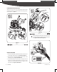
Front Tine Tiller » Operator’s Manual 11 mm REPLACING THE BELT 1. Remove the one bolt in the upper belt guard and four bolts in the lower belt guard to expose the belt assembly. (See Figure 13a) Transmission Pulley 13 mm 2. Loosen the two stud bolts that fix both belt guide rods. (See Figure 13b, Illustration 1) 3. Remove the belt from both the engine pulley and transmission pulley.
STORAGE If the front tine tiller will not be used for a period longer than 30 days, follow the steps below to prepare your unit for storage. 1. Drain the fuel tank completely. Stored fuel containing ethanol or MTBE can start to go stale in 30 days. Stale fuel has high gum content and can clog the carburetor and restrict fuel flow. 2. Start the engine and run until it stops. This helps prevent gum deposits from forming inside the carburetor and possible engine damage.
Front Tine Tiller Problem Engine runs erratically Engine overheats Engine will not stop when throttle control is positioned at stop, or engine speed does not increase properly when throttle control is adjusted. Cause » Operator’s Manual Remedy 1. Spark plug wire is loose 1. Connect and tighten spark plug wire 2. Unit running with Choke lever in CLOSE position 2. Move choke lever to OPEN position 3. Blocked fuel line or stale fuel 3. Clean fuel line. Fill tank with clean, fresh gasoline 4.
PARTS DIAGRAM 19 | Parts Diagram YT5328PM02 - 1807
Front Tine Tiller » Operator’s Manual PARTS LIST No. Description QTY. No. Description QTY.
No. 21 | Description QTY. No. Description QTY.
Front Tine Tiller YT5328PM02 - 1807 » Operator’s Manual Parts List | 22
yardmax.com Tame the Great Outdoors 847-327-0566 or 844-YARDMAX | ® info@yardmax.