
Full Product Manual
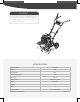

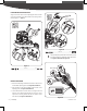

UPPER HANDLEBAR
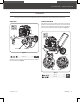
1. Remove two adjusting hand knobs, at washers and nuts from
the handlebar adjusting plates. (See Figure 5a, Illustration 1)
2. Align the holes in the upper handlebar with the holes in the
adjusting plates. (See Figure 5a, Illustration 2)
3. Insert M8×25 bolts in the lower holes, screw big washer and
M8 nuts. Insert adjusting hand knobs into the one of three
upper holes, screw big washer and M8 nuts. Tighten all the
four M8 nuts. (See Figure 5a, Illustration 3)
2
1
Adjusting Hand Knob
3
Bolt Hole
Adjusting Hole
M8×25 (×2)
Figure 5a
Figure 5b
17
mm
18
mm
30
mm
13
mm
11
mm
× 2
M8 × 25 × 2
4
The upper adjusting hand knobs can be used in one of
three hole positions for handlebar height adjustment.
( See Figure 5a, Illustration 2 & Figure 5b)
Normal Positon
Lower Positon
Upper Positon
ADJUSTABLE
HANDLE BARS
3-POSITION
1
2
Handlebar Adjusting Plate
M8×25 (×4)Bolt Hole
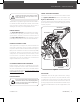
HANDLEBAR ADJUSTING PLATE
Align the two lower holes in each adjusting plate with the holes
in the lower handlebar. Insert M8×25 bolts and screw big washer,
M8 nuts tightly. (See Figure 4)
M8 × 25 × 4
3
Figure 4
17
mm
18
mm
30
mm
13
mm
11
mm
× 2
9
YT5328PM02 - 1807
|
Assembly