
Full Product Manual
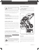


Driven Shaft
M10×50 (×2)
Inner Tine
2
1
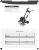
Lower Handlebar
Bolt Hole M8×45 (×2)
M8×25 (×2)
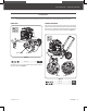
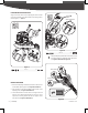
This front tine tiller was partially assembled at the factory. To assemble your machine follow the below instructions.
ASSEMBLY
LOWER HANDLEBARINNER TINE
Align the holes in the lower handlebar with the holes in the support
bracket. Insert the M8×45 bolts, spring washers, at washers into the
lower holes. Insert M8×25 bolts and screw big washers and M8 nuts
from other side. Tighten M8×45 bolts and M8 nuts. (See Figure 3)
Assemble two inner tines with gearbox shafts using two M10×50
bolts and M10 nuts. (See Figure 2)
Figure 3
Figure 2
17
mm
18
mm
30
mm
13
mm
11
mm
× 2
M8 × 45 × 2
2
M8 × 25 × 2
M10 × 50 × 2
1
16
mm
× 2
8
Front Tine Tiller
»
Operator’s Manual
YT5328PM02 - 1807
Assembly
|