AC Servo Drives Σ -V Series USER'S MANUAL INDEXER Module Model: SGDV-OCA03A Overview 1 Specifications 2 SERVOPACK Installation 3 Wiring and Connection 4 Parameter Setting and Functions 5 Program Table 6 Serial Command Communications 7 Operation of Digital Operator 8 Troubleshooting 9 Appendix MANUAL NO.
Copyright © 2009 YASKAWA ELECTRIC CORPORATION All rights reserved. No part of this publication may be reproduced, stored in a retrieval system, or transmitted, in any form, or by any means, mechanical, electronic, photocopying, recording, or otherwise, without the prior written permission of Yaskawa. No patent liability is assumed with respect to the use of the information contained herein.
About this Manual This manual describes information required for designing, trial operating, adjusting and maintaining the INDEXER Module for Σ-V Series SERVOPACKs. Be sure to refer to this manual and perform design and maintenance to select devices correctly. Keep this manual in a location where it can be accessed for reference whenever required. Description of Technical Terms The following table shows the meanings of terms used in this manual.
• Parameter Notation The following two types of notations are used for parameter digit places and settings. Example Notation Example for Pn000 Pn000㧩㨚 㧜㧜㧜㧜 Notation Method Digit Notation Meaning Set Value Notation Notation Method Meaning Indicates that digit 1 of the Pn000.0 = x Indicates digit 1 parameter (Pn000) is x. of the parameter (Pn000). or n. x Indicates that digit 2 of the Pn000.1 = x Indicates digit 2 parameter (Pn000) is x. of the parameter (Pn000). or n. x Digit 1 Pn000.
Safety Information The following conventions are used to indicate precautions in this manual. Failure to heed precautions provided in this manual can result in serious or possibly even fatal injury or damage to the products or to related equipment and systems. WARNING CAUTION PROHIBITED MANDATORY Indicates precautions that, if not heeded, could possibly result in loss of life or serious injury.
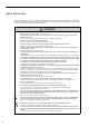
Safety Precautions These safety precautions are very important. Read them before performing any procedures such as checking products on delivery, storage and transportation, installation, wiring, operation and inspection, or disposal. Be sure to always observe these precautions thoroughly. WARNING • Never touch any rotating motor parts while the motor is running. Failure to observe this warning may result in injury.
Storage and Transportation CAUTION • Do not store or install the product in the following locations. Failure to observe this caution may result in fire, electric shock, or damage to the product.
Wiring CAUTION • Be sure to wire correctly and securely. Failure to observe this caution may result in motor overrun, injury, or malfunction. • Do not connect a commercial power supply to the U, V, or W terminals for the servomotor connection. Failure to observe this caution may result in injury or fire. • Securely connect the main circuit power supply terminal screws, control power supply terminal screws, and servomotor connection terminal screws. Failure to observe this caution may result in fire.
Operation CAUTION • Always use the servomotor and SERVOPACK in one of the specified combinations. Failure to observe this caution may result in fire or malfunction. • Conduct trial operation on the servomotor alone with the motor shaft disconnected from the machine to avoid accidents. Failure to observe this caution may result in injury. • During trial operation, confirm that the holding brake works correctly. Furthermore, secure system safety against problems such as signal line disconnection.
Disposal CAUTION • When disposing of the products, treat them as ordinary industrial waste. General Precautions Observe the following general precautions to ensure safe application. • The products shown in illustrations in this manual are sometimes shown without covers or protective guards. Always replace the cover or protective guard as specified first, and then operate the products in accordance with the manual.
Warranty (1) Details of Warranty Warranty Period The warranty period for a product that was purchased (hereinafter called “delivered product”) is one year from the time of delivery to the location specified by the customer or 18 months from the time of shipment from the Yaskawa factory, whichever is sooner. Warranty Scope Yaskawa shall replace or repair a defective product free of charge if a defect attributable to Yaskawa occurs during the warranty period above.
(3) Suitability for Use 1. It is the customer’s responsibility to confirm conformity with any standards, codes, or regulations that apply if the Yaskawa product is used in combination with any other products. 2. The customer must confirm that the Yaskawa product is suitable for the systems, machines, and equipment used by the customer. 3. Consult with Yaskawa to determine whether use in the following applications is acceptable.
Applicable Standards North American Safety Standards (UL) Model UL∗ Standards (UL File No.) SERVOPACK • SGDV UL508C (E147823) Servomotor • • • • • UL1004 (E165827) SGMJV SGMAV SGMPS SGMGV SGMSV ∗ Underwriters Laboratories Inc. Note: Applicable when the INDEXER Module is attached to the SERVOPACKs for the command option attachable type.
Contents About this Manual . . . . . . . . . . . . . . . . . . . . . . . . . . . . . . . . . . . . . . . . . . . . . . . . . . . . . . . . iii Safety Precautions. . . . . . . . . . . . . . . . . . . . . . . . . . . . . . . . . . . . . . . . . . . . . . . . . . . . . . . . vi Warranty. . . . . . . . . . . . . . . . . . . . . . . . . . . . . . . . . . . . . . . . . . . . . . . . . . . . . . . . . . . . . . . . xi Applicable Standards . . . . . . . . . . . . . . . . . . . . . . . . . . . . . . . . . . . . . .
Chapter 5 Parameter Setting and Functions . . . . . . . . . . . . . . . . . . . . . . . .5-1 5.1 Parameter Configurations . . . . . . . . . . . . . . . . . . . . . . . . . . . . . . . . . . . . . . . 5-2 5.2 Restrictions on SGDV SERVOPACK Parameters . . . . . . . . . . . . . . . . . . . . . 5-3 5.3 Sequence I/O Signals . . . . . . . . . . . . . . . . . . . . . . . . . . . . . . . . . . . . . . . . . . 5-5 5.3.1 Servo ON Signal (/S-ON) . . . . . . . . . . . . . . . . . . . . . . . . . . . . . . . . . . . . .
Chapter 7 Serial Command Communications . . . . . . . . . . . . . . . . . . . . . . .7-1 7.1 CN12 Connector Specifications . . . . . . . . . . . . . . . . . . . . . . . . . . . . . . . . . . . 7-2 7.2 Settings . . . . . . . . . . . . . . . . . . . . . . . . . . . . . . . . . . . . . . . . . . . . . . . . . . . . . 7-3 7.2.1 Block Diagram . . . . . . . . . . . . . . . . . . . . . . . . . . . . . . . . . . . . . . . . . . . . . . . . . . . . . . . . . . 7-3 7.2.2 Setting the Axis Address . . . . . . . . . . .
Chapter 10 Appendix. . . . . . . . . . . . . . . . . . . . . . . . . . . . . . . . . . . . . . . . .10-1 10.1 10.2 10.3 10.4 10.5 10.6 Parameter List for INDEXER Module. . . . . . . . . . . . . . . . . . . . . . . . . . . . . 10-2 Parameter List for Command Option Attachable Type SERVOPACKs . . . 10-9 Monitor Modes . . . . . . . . . . . . . . . . . . . . . . . . . . . . . . . . . . . . . . . . . . . . . 10-26 Utility Functions . . . . . . . . . . . . . . . . . . . . . . . . . . . . . . . . . . . . . . . .
1 Overview This chapter gives an overview of the INDEXER Module and describes how to check parts upon delivery. 1.1 Checking Products on Delivery . . . . . . . . . . . . . . . . . . . . . . . . . . . . . . . . . 1-2 1.2 Nameplate and Model Designation . . . . . . . . . . . . . . . . . . . . . . . . . . . . . . 1-3 Overview 1.3 Nameplate Location . . . . . . . . . . . . . . . . . . . . . . . . . . . . . . . . . . . . . . . . .
1 Overview 1.1 Checking Products on Delivery (1) When the INDEXER Module is Not Connected to the SERVOPACK 1. Mount the INDEXER Module to the SERVOPACK as described in the enclosed Σ-V Series 2. INDEXER Module Installation Guide (TOBP C720829 02). For the location of the nameplate, refer to 1.3 Nameplate Location. Check the nameplate to confirm that the product is the one that was ordered. For the nameplate, refer to 1.2 Nameplate and Model Designation.
1.2 Nameplate and Model Designation Nameplate and Model Designation Nameplate Example Option Module model number Name OPTION MODULE MODEL SGDV-OCA03A 840204-9-1 D0093A102110001 SGDV YASKAWA ELECTRIC CORPORATION Manufacturing number Nameplate Model Designation SGDV – OC A03 A Series SGDV Σ-V Series 1st + 2nd digits: Module Type Module Code OC Command option module 6th digit: Design Revision Order 3rd + 4th + 5th digits: Interface Specifications Interface Code INDEXER A03 Overview 1.
1 Overview 1.3 Nameplate Location Nameplate (Model no.
2 Specifications This chapter gives an overview and describes the specifications of the INDEXER Module. 2.1 Product Overview . . . . . . . . . . . . . . . . . . . . . . . . . . . . . . . . . . . . . . . . . . . . 2-2 2.1.1 Main Functions . . . . . . . . . . . . . . . . . . . . . . . . . . . . . . . . . . . . . . . . . . . . . . . . . . . . . . . 2-2 2.1.2 Features of Firmware Versions . . . . . . . . . . . . . . . . . . . . . . . . . . . . . . . . . . . . . . . . . . 2-3 2.2 General Specifications . . .
2 Specifications 2.1.1 Main Functions 2.1 Product Overview The INDEXER Module is a single-axis positioning device that is equipped with a program table operation function. The INDEXER Module is mounted to the side of the SERVOPACK. The INDEXER Module has two reference methods: digital I/O and serial commands. Digital I/O is structured as a program table (Mode 0) or homing/JOG speed table (Mode 1).
2.1 Product Overview INDEXER Module Serial Current control CPU Speed control Local I/O Position control DO Profiler operation DI Dual-port RAM SGDV SERVOPACK M Counter ENC RS422/485 Block Diagram Features of Firmware Versions The table below lists the differences between firmware versions for the INDEXER Module. Some functions are included in every version, and have upward compatibility. Firmware Features Version 1 Version 3 Fully-closed loop control Cannot be supported.
2 Specifications 2.2 General Specifications This table lists the general specifications of the INDEXER Module. Applicable SERVOPACK Σ-V Series SGDV- Placement Attached to the SERVOPACK Power Power Supply Method Specifications Supplied from the control power supply of the SGDV SERVOPACK. Operating Conditions Surrounding Air/Storage Temperature 0°C to +55°C/ -20°C to +85°C Ambient/Storage Humidity 90% RH or less (with no condensation) Vibration/Shock Resistance 4.9 m/s2 / 19.
2.3 Part Names of the INDEXER Module Part Names of the INDEXER Module The following figure shows the part names of the INDEXER Module. With front cover open Reserved (Do not use.) Reserved (Do not use.) LED (red) LED (green) I/O signal connector (CN11) for sequence I/O signals Serial command communications connector (CN12) Specifications 2.
2 Specifications 2.4 LED Indicators The following table shows the meaning of the LED indicators.
3 SERVOPACK Installation This chapter describes how to install the SERVOPACK. 3.1 SERVOPACK Installation Environment and Applicable Standards . . . . . . 3-2 3.1.1 Installation Environment . . . . . . . . . . . . . . . . . . . . . . . . . . . . . . . . . . . . . . . . . . . . . . . 3-2 3.1.2 Installation Conditions for Applicable Standards . . . . . . . . . . . . . . . . . . . . . . . . . . . . . 3-2 3.2 SERVOPACK Installation . . . . . . . . . . . . . . . . . . . . . . . . . . . . . . . . . . . . .
3 SERVOPACK Installation 3.1.1 Installation Environment 3.1 SERVOPACK Installation Environment and Applicable Standards SERVOPACK installation environment and applicable standards are as follows. 3.1.1 Installation Environment Surrounding air temperature: 0°C to 55°C Ambient humidity: 90% RH or less (with no condensation) Altitude: 1,000 m or less Vibration resistance: 4.9 m/s2 Shock resistance: 19.
3.2 SERVOPACK Installation 3.2 SERVOPACK Installation 3.2.1 Orientation The SERVOPACK is available in models that are base-mounted, models that are rack-mounted, and models that are duct-ventilated. In any case, mount the SERVOPACK with a vertical orientation. Firmly secure the SERVOPACK to the mounting surface, using either two to four mounting holes depending on the SERVOPACK capacity.
3 SERVOPACK Installation 3.2.2 Installation Standards 3.2.2 Installation Standards Observe the standards for mounting SERVOPACKs in control panels, including those for the mounting SERVOPACKs side by side in one control panel as shown in the following illustration. • SERVOPACK Mounting Orientation Mount the SERVOPACK vertically to the base, with the front panel (the side with the panel operator display) facing out.
3.3 EMC Installation Conditions EMC Installation Conditions This section describes the recommended installation conditions that satisfy EMC guidelines for each model of the SGDV SERVOPACK. The conditions required for the standard type (base-mounted) of SERVOPACK are described. Refer to this section for other SERVOPACK models such as the rack-mounted types as well. This section describes the EMC installation conditions satisfied in test conditions prepared by Yaskawa.
3 SERVOPACK Installation Three-phase 200 V • SGDV-AE1A ( = R70, R90, 1R6, 2R8, 3R8, 5R5, 7R6) + SGDV-OCA03A • SGDV-AE5A ( = R70, R90, 1R6, 2R8, 3R8, 5R5, 7R6) + SGDV-OCA03A Shield box Brake power supply Brake Core L1, L2, L3 Clamp U, V, W Core Core Noise filter 3 One turn CN2 PE CN1 CN8 Core Core Two turn Clamp 1 INDEXER Module 4 Core L1C, L2C Clamp Surge absorber Servomotor One turn Core Core Clamp Power supply: Three-phase 200 VAC 5 Clamp One turn SERVOPACK E
3.
3 SERVOPACK Installation Three-phase 200 V • SGDV-AE1A ( = 180, 200, 330) + SGDV-OCA03A • SGDV-AE5A ( = 180, 200, 330) + SGDV-OCA03A Shield box Brake power supply L1, L2, L3 Core Clamp U, V, W Noise filter 3 PE CN1 CN8 Core Core Two turn Clamp 1 Servomotor INDEXER Module 4 Core CN2 Clamp L1C, L2C Surge absorber 3-8 Cable Name Encoder One turn CN11 CN12 2 Host Safety Host Host controller unit controller controller Symbol Brake One turn Core Clamp Power supply: T
3.
3 SERVOPACK Installation Three-phase 400 V • SGDV-DE1A ( = 1R9, 3R5, 5R4, 8R4, 120, 170) + SGDV-OCA03A • SGDV-DE5A ( = 1R9, 3R5, 5R4, 8R4, 120, 170) + SGDV-OCA03A Noise filter*2 Brake power supply One turn Clamp Core Servomotor One turn One turn PE CN1 CN8 Core Core Two turn Clamp 1 4 Core CN2 Surge absorber 3 Brake L1, L2, L3 Clamp Noise filter*3 U, V, W 24 V, 0 V Clamp SERVOPACK Core Control power supply 24 VDC*1 Core 6 Power supply: Three-phase 400 VAC Clamp Su
3.
4 Wiring and Connection This chapter describes examples of how a system is configured using the INDEXER Module and how the I/O signals are connected. For details on the main circuit, encoders, safety devices, and regenerative resistors, refer to the following manual. For more information on safe and stable usage of the servo system, be sure to read the precautions in the section labeled, " IMPORTANT," in the following manuals.
4 Wiring and Connection 4.1.1 Connecting to SGDV-FE1A SERVOPACK 4.1 System Configuration Diagram Examples of basic servo system configurations are shown for each SERVOPACK type. 4.1.1 Connecting to SGDV-FE1A SERVOPACK Power supply: Single-phase 100 VAC R T Molded-case circuit breaker (MCCB) Protects the power supply line by shutting the circuit OFF when overcurrent is detected. Noise filter Used to eliminate external noise from the power line.
4.1 System Configuration Diagram 4.1.2 Connecting to SGDV-AE1A SERVOPACK (1) Using a Three-phase, 200 V Power Supply Power supply Three-phase 200 VAC R S T Molded-case circuit breaker (MCCB) Protects the power supply line by shutting the circuit OFF when overcurrent is detected. Digital operator Noise filter SGDV- AE1A SERVOPACK Used to eliminate external noise from the power line. INDEXER Module Sequence I/O signal cable Magnetic contactor Host controller Turns the servo ON and OFF.
4 Wiring and Connection 4.1.2 Connecting to SGDV-AE1A SERVOPACK (2) Using a Single-phase, 200 V Power Supply The Σ-V Series SERVOPACK for a 200-V power supply input has input specifications for a three-phase power supply, but some models can also be used with a single-phase 200-V power supply. For details, refer to Σ-V Series User's Manual Design and Maintenance Rotational Motor/Command Option Attachable Type (SIEP S800000 60).
4.1 System Configuration Diagram 4.1.3 Connecting to SGDV-DE1A SERVOPACK Power supply Three-phase 400 VAC RST Molded-case circuit breaker (MCCB) Protects the power supply line by shutting the circuit OFF when overcurrent is detected. Digital operator INDEXER Module SGDV- DE1A SERVOPACK Noise filter Used to eliminate external noise from the power line. Sequence I/O signal cable Host controller Connection cable for digital operator Magnetic contactor Turns the servo ON and OFF.
4 Wiring and Connection 4.1.4 Connecting to SGDV-FE5A SERVOPACK 4.1.4 Connecting to SGDV-FE5A SERVOPACK Power supply: Single-phase 100 VAC R T Molded-case circuit breaker (MCCB) Protects the power supply line by shutting the circuit OFF when overcurrent is detected. Noise filter Used to eliminate external noise from the power line. Digital operator SGDV- FE5A SERVOPACK INDEXER Module Sequence I/O signal cable Magnetic contactor Host controller Turns the servo ON and OFF.
4.1 System Configuration Diagram 4.1.5 Connecting to SGDV-AE5A SERVOPACK (1) Using a Three-phase, 200 V Power Supply Power supply Three-phase 200 VAC R S T Molded-case circuit breaker (MCCB) Protects the power supply line by shutting the circuit OFF when overcurrent is detected. Noise filter Used to eliminate external noise from the power line. Digital operator SGDV- AE5A SERVOPACK INDEXER Module Sequence I/O signal cable Magnetic contactor Host controller Turns the servo ON and OFF.
4 Wiring and Connection 4.1.5 Connecting to SGDV-AE5A SERVOPACK (2) Using a Single-phase, 200 V Power Supply The Σ-V Series SERVOPACK for a 200-V power supply input has input specifications for a three-phase power supply, but some models can also be used with a single-phase 200-V power supply. For details, refer to Σ-V Series User's Manual Design and Maintenance Linear Motor/Command Option Attachable Type (SIEP S800000 66).
4.1 System Configuration Diagram 4.1.6 Connecting to SGDV-DE5A SERVOPACK Power supply Three-phase 400 VAC RST Molded-case circuit breaker (MCCB) Protects the power supply line by shutting the circuit OFF when overcurrent is detected. Digital operator INDEXER Module SGDV- DE5A SERVOPACK Noise filter Used to eliminate external noise from the power line. Sequence I/O signal cable Host controller Connection cable for digital operator Magnetic contactor Turns the servo ON and OFF.
4 Wiring and Connection 4.2.1 I/O Signal Names and Functions 4.2 I/O Signal Connections This section describes the names and functions of I/O signals. Also terminal layout and connection examples by control method are shown. 4.2.1 I/O Signal Names and Functions The following table shows the names and functions of I/O signals. Provide an external power supply; the SERVOPACK and INDEXER Module do not have an internal 24-V power supply.
4.2 I/O Signal Connections (2) Output Signals Signal Name Pin No. Name ALM+ 3 ALM- 4 /WARN+ (/SO1+) 1 /WARN(/SO1-) 2 /BK+ (/SO2+) 23 /BK(/SO2-) 24 /S-RDY+ (/SO3+) 25 /S-RDY(/SO3-) 26 FG Connector Shell Function Servo Alarm Output Servo Alarm: Turns OFF when an error is detected. Warning Signal Output Error/Warning: ON for 2 seconds when an error has occurred. ON continuously while a warning is being detected.
4 Wiring and Connection 4.2.1 I/O Signal Names and Functions Signal Name Pin No. Function +24V/COM 1 Power Supply for Sequence Signals. Voltage range: 24 VDC ± 10% /MODE 0/1 3 This pin switches between Mode 0 and Mode 1. ON: Mode 0 (program table operation) OFF: Mode 1 (JOG speed table operation or homing) Mode 0: /START-STOP; /HOME 5 Mode 1: Mode 0: 4-12 /PGMRES; /JOGP 7 /SEL0; /JOGN 9 /SEL1; /JOG0 Mode 1: When ON, starts or restarts program table operation.
4.2 I/O Signal Connections (4) CN11 Output Signals Pin No.
4 Wiring and Connection 4.2.2 Interface Circuits 4.2.2 Interface Circuits This section shows examples of SERVOPACK I/O signal connection to the host controller. (1) Interfaces with Sequence Input Circuits The sequence input circuit interface connects through a relay or open-collector transistor circuit. Select a lowcurrent relay otherwise a faulty contact will result. INDEXER Module and SERVOPACK 24 VDC 50 mA min. INDEXER Module and SERVOPACK 24 VDC 50 mA min. +24 V/COM 3.3 k Ω +24 V/COM 3.
4.2 I/O Signal Connections (2) Interfaces with Output Circuits The SERVOPACK signals use the following types of output circuits. Construct an input circuit on the host controller side to match the output circuit. • Connecting to a Photocoupler Output Circuit Connect a photocoupler output circuit through a relay or line receiver circuit.
4 Wiring and Connection 4.2.3 Example of I/O Signal Connections 4.2.3 Example of I/O Signal Connections The following diagram shows a typical connection example. Photocoupler output Max. operating voltage: 30 VDC Max. operating current: 50 mA DC SGDV SERVOPACK CN1 Control power supply *3 for sequence signal +24 VIN +24 V /SI1 /ALM-RST 6 3.
4.2 I/O Signal Connections SGDV SERVOPACK CN10 (Sinking or sourcing) CN11 1 CN11 3.
4 Wiring and Connection 4.3.1 Communications Specifications 4.3 Serial Command Communications Connector (CN12) Serial commands can be used to perform operations such as positioning, setting parameters and program tables, monitoring, and other operations. RS-422 or RS-485 Host controller 4.3.1 Communications Specifications The following table shows the communications specifications of the CN12 connector.
4.3 Serial Command Communications Connector (CN12) 4.3.2 Communications Connector (1) Connector Model INDEXER Module-end Connector 10214-52A2PL 14P Solder Type 10114-3000PE Case Manufacturer 10314-52A0-008 Sumitomo 3M Limited Connector Signal Names Pin No.
4 Wiring and Connection 4.3.4 Connection Examples 4.3.4 Connection Examples (1) Full-duplex Wiring RS-422 or RS-485 port INDEXER Module Signal Name Signal Name Pin No. RXD TXD 1 /RXD /TXD 2 TXD RXD 3 /TXD /RXD 4 0V GND 5 FG /RXD 6 RT 7 TXD 8 /TXD 9 RXD 10 GND 14 * Case FG To next axis Pin No. 1 2 3 4 14 FG Full-duplex Wiring ∗ Connect (short) the RT and /RXD pins in the last axis. Note: Cable length: 50 m max.
4.3 Serial Command Communications Connector (CN12) RS-422/RS-485 Interface The maximum total length for RS-422 or RS-485 cable is 50 m. Use the minimum length of cable that is needed. The INDEXER Module’s communications circuits are not insulated. If communications errors occur because of noise, use noise suppression methods such as shielded cable or ferrite cores.
4 Wiring and Connection 4.4 Power Loss in the INDEXER Module Power loss in the INDEXER Module is shown below. The INDEXER Module’s power is supplied from the SERVOPACK. INDEXER Module Specifications Item Specifications Min. operating voltage 5.05 V Max. operating voltage 5.25 V Max. operating current 500 mA Max. power loss 2.6 W For the SERVOPACK power losses at the rated output, refer to the following manuals. • 3.
5 Parameter Setting and Functions This chapter describes the use of the I/O signals in the SGDV SERVOPACK and INDEXER Module (I/O signals in the CN1 and CN11 connectors) as well as the procedure for setting the related parameters for the intended purposes. The following sections can be used as references for this chapter. • Lists of CN1 and CN11 I/O signals: Refer to 4.2.1 I/O Signal Names and Functions. • List of parameters: Refer to 10.1 Parameter List for INDEXER Module. 5.1 Parameter Configurations .
5 Parameter Setting and Functions 5.1 Parameter Configurations Parameters are comprised of the types shown in the following table. Refer to Chapter 10. Type 5-2 Parameter No. Description Function Selection Parameters Pn000 to Pn010 PnB1F Select basic and application functions such as the type of control mode or the stop method when an alarm occurs. Servo Gain and Other Parameters Pn100 to Pn170 Set numerical values such as speed and position loop gains.
5.2 Restrictions on SGDV SERVOPACK Parameters 5.2 Restrictions on SGDV SERVOPACK Parameters The following parameters are set automatically when an INDEXER Module is installed on an SGDV SERVOPACK. Do not change these parameters because they are reserved for system use. Also, the SGDV SERVOPACK will be set for position control. It is not necessary to set parameters related to speed control or torque control, so those parameters should not be changed.
5 Parameter Setting and Functions Parameter No. Digit Pn512 Pn517 Pn522 ∗ 5-4 Description Setting Description 0 Output Signal Inversion for CN1-1 or -2 Terminals 0 or 1 The INDEXER Module sets a value matched to PnB1C and PnB51. 1 Output Signal Inversion for CN1-23 or -24 Terminals 0 or 1 The INDEXER Module sets a value matched to PnB1D and PnB51. 2 Output Signal Inversion for CN1-25 or -26 Terminals 0 or 1 The INDEXER Module sets a value matched to PnB1E and PnB51.
5.3 Sequence I/O Signals 5.3 Sequence I/O Signals This section explains sequence I/O signals. In this section, the word “open” or “close” shown in parentheses in parameter descriptions indicates that the contact is open or closed. 5.3.1 Servo ON Signal (/S-ON) This sets the servo ON signal (/S-ON) that determines whether the servomotor power is ON or OFF. Type Connector Pin No. Name Input /S-ON Setting Meaning ON Servomotor power is ON. Servomotor can be operated. OFF Servomotor power is OFF.
5 Parameter Setting and Functions 5.3.2 Overtravel (2) Changing Input Signal Settings The settings of the input signals for overtravel can be changed with the parameters below. Parameter Meaning When Enabled 0 [Factory setting] When input signal is OFF (open), forward run is prohibited (forward overtravel). 1 When input signal is ON (close), forward run is prohibited (forward overtravel). 2 Forward run is always prohibited (forward overtravel). 3 Forward run is always enabled.
5.3 Sequence I/O Signals 5.3.3 Servo Alarm Output Signal (ALM) and Alarm Code Output Signals (/ALO1, /ALO2, and /ALO3) This section describes signals that are output when the SERVOPACK detects errors and resetting methods. (1) Servo Alarm Output Signal (ALM) This signal is output when the SERVOPACK detects an error. Configure an external circuit so that this alarm output turns OFF the main circuit power supply for the SERVOPACK whenever an error occurs. Type Output Connector Pin No.
5 Parameter Setting and Functions 5.3.4 Braking Signal (/BK) The setting of the /ALM-RST signal can be changed with the parameter below. Parameter PnB52 Meaning 0 [Factory setting] Resets alarms by switching input signal from OFF (open) to ON (close). 1 Resets alarms by switching input signal from ON (close) to OFF (open). 2 After restart Does not reset alarms. (Signal is ignored.) 3 5.3.4 When Enabled Braking Signal (/BK) • Inverting the polarity of the brake output signal (/BK), i.e.
5.3 Sequence I/O Signals 5.3.5 Servo Ready Output Signal (/S-RDY) This signal is turned ON when the SERVOPACK is ready to accept the servo ON (/S-ON) signal. The /S-RDY signal is turned ON under the following conditions. • The main circuit power supply is ON. • No hard wire base block state • No servo alarms Type Output Signal Name Connector Pin No. /S-RDY Setting Meaning ON (close) SERVOPACK is ready to accept the servo ON signal (/S-ON).
5 Parameter Setting and Functions 5.3.7 Positioning Completed Output Signal (/INPOSITION) 5.3.7 Positioning Completed Output Signal (/INPOSITION) This signal indicates that servomotor positioning has been completed. The signal is output when the motor stops, even if the current position has not reached the target position.
5.3 Sequence I/O Signals 5.3.8 Programmable Output Signals (/POUT0 to /POUT7) The basic use and wiring procedure for the programmable outputs (/POUT0 to /POUT7) are given below. The programmable output signals can be changed by the user through the program table’s POUT bits or the POUT serial command. (1) Signal Specifications Type Signal Name Output Connector Pin No.
5 Parameter Setting and Functions 5.3.9 Encoder Signal Outputs 5.3.9 Encoder Signal Outputs The encoder signals can be used to monitor the servomotor’s speed and position. However, the INDEXER Module manages the servomotor’s speed and position so it is not necessary to use the encoder signals to monitor the speed and position from the host controller. If an absolute encoder is used, the absolute position data is sent only once when the power is turned ON. Normally, do not use this signal.
5.4 Settings According to Device Characteristics 5.4 Settings According to Device Characteristics This section describes the procedure for setting parameters according to the dimensions and performance of the equipment used. 5.4.1 Setting Reference Units Reference units are the position and distance units that are used between the host controller and INDEXER Module. A reference unit is the minimum unit for positioning. The electronic gear ratio converts encoder pulse units into reference units.
5 Parameter Setting and Functions 5.4.1 Setting Reference Units (3) Setting Speeds in Reference Units Calculate the positioning speed. Reference unit: 0.01 mm Desired positioning speed: 15 m/min 15000 mm/min 0.01 mm = 1500000 reference units/min Thus, the positioning speed setting is 1500 [1000 reference units/min]. Specify the positioning speed and registration speed in the program table in SPD and RSPD. Specify the JOG speed in the JOG speed table in JSPD.
5.4 Settings According to Device Characteristics Using the parameters below, set the acceleration and deceleration, and set the average movement time of position references.
5 Parameter Setting and Functions 5.4.2 Moving Mode and Coordinate Settings 5.4.2 Moving Mode and Coordinate Settings Use the following parameters to set the moving mode and coordinates. Parameter Meaning When Enabled 0 Sets coordinates to linear type. [Factory setting] PnB20 PnB21 PnB23 PnB25 1 Sets coordinates to rotary type. Moving mode is set as shortest path. 2 Sets coordinates to rotary type. Moving mode is set as always forward. 3 Sets coordinates to rotary type.
5.4 Settings According to Device Characteristics (2) When the Coordinates are the Rotary Type When using a rotary type coordinates such as with a rotary table, set PnB20 to 1 (shortest path), to 2 (forward), or to 3 (reverse). Then set the end point of rotational coordinates in PnB21 and the starting point of rotational coordinates in PnB23. The software limit function will be disabled.
5 Parameter Setting and Functions 5.4.3 Setting Home Position 5.4.3 Setting Home Position Set the origin or the difference between the reference coordinates and absolute encoder position (the absolute encoder offset) for parameter PnB25.
5.4 Settings According to Device Characteristics 5.4.4 Backlash Compensation This parameter can be set to compensate for positioning offset caused by the backlash of gears. Backlash Compensation PnB50 Setting Range Setting Unit Factory Setting When Enabled -1000 to 1000 Reference unit 0 Immediately Specify the direction for compensation with the sign and the quantity of the compensation with a numeric value. If the sign is positive, compensation will be applied for forward positioning.
5 Parameter Setting and Functions 5.4.6 Fully-closed Loop Control 5.4.6 Fully-closed Loop Control For more information on the settings for fully-closed loop control, refer to Σ-V Series User’s Manual Design and Maintenance Rotational Motor/Command Option Attachable Type (SIEP S800000 60). When using the fully-closed loop control with an INDEXER Module, some restrictions apply to the setting for parameter Pn20A (External Encoder Pitches.
6 Program Table The chapter describes how to set and operate a program table. 6.1 Program Table . . . . . . . . . . . . . . . . . . . . . . . . . . . . . . . . . . . . . . . . . . . . . . 6-2 6.1.1 Mode Switch Signal (/MODE 0/1) . . . . . . . . . . . . . . . . . . . . . . . . . . . . . . . . . . . . . . . . 6-2 6.1.2 Input Signals for Program Table Operation . . . . . . . . . . . . . . . . . . . . . . . . . . . . . . . . . 6-2 6.1.3 Program Table Step Selection . . . . . . . . . . . . . . . . . . . . . .
6 Program Table 6.1.1 Mode Switch Signal (/MODE 0/1) 6.1 Program Table This section explains program table. In this section, the word “open” or “close” shown in parentheses in parameter descriptions indicates that the contact is open or closed. 6.1.1 Mode Switch Signal (/MODE 0/1) If the /MODE 0/1 input signal is active, the mode is set to program table operation mode (Mode 0). (1) Signal Specifications Type Connector Pin No.
6.1 Program Table (2) Related Parameters Make the settings for program table operation with the parameters below. Parameter Meaning When Enabled Starts program table operation when /START-STOP signal is ON 0 (close). [Factory setting] Stops program table operation when /START-STOP signal is OFF (open). PnB04 Starts program table operation when /START-STOP signal is OFF (open). Stops program table operation when /START-STOP signal is ON (close).
6 Program Table 6.1.3 Program Table Step Selection 6.1.3 Program Table Step Selection Use the 8-bit selection signals (/SEL0 to /SEL7) to specify PGMSTEP 0 to 255.
6.1 Program Table 6.1.4 Program Table Settings This section explains the program table settings. If the edited program table is saved to flash memory, it will be saved even after the control power supply is turned OFF. Use one of the following methods to save the program table to flash memory. • Execute the PGMSTORE serial command • Select “Save Program Table” from SigmaWin+ • Use the FnB03 utility function* to save program tables *The function FnB03 is available for the following software versions.
6 Program Table 6.1.4 Program Table Settings Item RSPD Function Registration speed Description 1 to 99999999: Registration speed [1000 reference units/min] The factory setting is 1000. 1 to 99999999: Acceleration [1000 (reference units/min)/ms] ACC Acceleration “:”: Continues with acceleration specified in the most previously executed program step. If “:” is set for the first step in program operation, the last acceleration enabled before the start of program operation (e.g.
6.1 Program Table Item Function Description Set the condition to use to determine when the program step has been completed. For example, with the factory setting of IT0, the pass condition is met 0 ms after /INPOSITION becomes active. When the pass condition is met, the PGMSTEP that was specified for NEXT will be executed if the number of execution times specified for LOOP has been reached. If the number of execution times specified for LOOP has not been reached, execution is repeated again.
6 Program Table 6.1.5 Examples of EVENT Conditions Note 1. An error (E53E) will occur and program table operation will be stopped if a new positioning command is received during positioning. To restart, turn the /START-STOP signal OFF and then ON again. The execution will be started from the next step when restarting. 2. When the target position (POS) is +INFINITE or -INFINITE and the registration distance (RDST) is “-”, the Speed can be changed by executing the next PGMSTEP.
6.1 Program Table 6.1.6 Program Table Operation (1) Starting and Stopping the Program If the /START-STOP signal becomes active when program table operation has been canceled, /SEL0 to /SEL7 will be latched and the program will be executed from the PGMSTEP specified with /SEL0 to /SEL7. Speed t /START-STOP Canceled Operating Latched /SEL0 to /SEL7 If the /START-STOP returns to inactive state, the program will be stopped and the motor will stop (positioning will be stopped).
6 Program Table 6.1.7 Status Changes in Program Table Operation (2) Resetting the Program The program will be canceled if the /PGMRES signal becomes active while the program is stopped (when the /PGMRES signal is on the rising edge and the /START-STOP signal is inactive.) Operating /START-STOP Canceled /PGMRES 6.1.7 Stopped Canceled Rising edge Status Changes in Program Table Operation There are three different statuses for program table operation. The initial status is “canceled.
6.1 Program Table 6.1.8 Input Signal Timing Specifications for Program Table Operation The following figures show the timing specifications of program table input signals. /MODE 0/1 /START-STOP 4 ms min. 0 ms min. /PGMRES /START-STOP 4 ms min. 4 ms min. /START-STOP /SEL0 to /SEL7 2 ms min. 4 ms min. • When /SEL0 to /SEL7 are specified in EVENT /SEL0 to /SEL7 0 ms min. 4 ms min., EVENT time max.
6 Program Table 6.1.9 Response Times after Turning ON the /START-STOP Signal 6.1.9 Response Times after Turning ON the /START-STOP Signal The response times after turning ON the /START-STOP signal are shown below. /START-STOP Motor movement /INPOSITION /POUT0 to 7 tM tI tP Time ∗ 6-12 Normal Under Special Conditions* tM 2 ms to 6 ms 2 ms to 16 ms tI 2 ms to 8 ms 2 ms to 14 ms tp 2 ms to 6 ms 2 ms to 10 ms Special Conditions • Program is stopped due to error.
6.1 Program Table 6.1.10 Program Table Examples This section provides examples of program tables.
6 Program Table 6.1.
6.
6 Program Table 6.1.
6.1 Program Table (6) Using INFINITE PGMSTEP POS SPD RDST RSPD ACC DEC POUT EVENT LOOP NEXT 0 +INFINITE 15000 – 1000 : : NNNNNNNN T2000 1 1 1 +INFINITE 30000 – 1000 : : :::::::: SEL0TO 1 2 2 STOP 30000 – 1000 : : :::::::: IT0 1 3 3 A+400000 30000 – 1000 : : :::::::: SEL1TO 1 0 PGMSTEP 2 PGMSTEP 0 PGMSTEP 0 PGMSTEP 3 PGMSTEP 1 PGMSTEP 2 PGMSTEP 3 PGMSTEP 1 2s 2s Speed /START-STOP /SEL0 /SEL1 /INPOSITION (7) Using Registration Refer to 6.
6 Program Table 6.1.10 Program Table Examples (8) Using Continuous Stop Function PGMSTEP POS SPD RDST RSPD ACC DEC POUT EVENT LOOP NEXT 0 +INFINITE 1080000 – – 1080 1080*1 NNNNNNNA T2000 1*2 1 1 S+45000 1000*3 – – 1080*4 1080 1*2 END NNNNNNAN SEL5T0 ∗1. When using the continuous stop function, the Deceleration (DEC) specified in the preceding program step is disabled. The servomotor decelerates at the set rate in the program step specified by the continuous stop function.
6.2 Registration 6.2 Registration Positioning is performed for the specified distance and specified speed from the position where the /RGRT signal is latched. Speed Registration distance Registration speed t /RGRT Registration Timing Specifications The following figure shows the latch timing specifications. /RGRT Latch operation • Shifting to registration operation 8 ms max. Speed t /RGRT Program Table 6.2.
6 Program Table 6.2.2 Registration Input Setting 6.2.2 Registration Input Setting Parameter PnB12 sets the logic for the /RGRT Registration Latch Signal. (1) Signal Specifications Type Signal Name Input /RGRT Connector Pin No. Setting Meaning ON (close) The current position has reached the latch position. OFF (open) The current position has not reached the latch position, or has passed the latch position. CN1-12 (2) Related Parameters The /RGRT signal can be set with the parameter below.
6.2 Registration The second and later latch signals are ignored. Speed t /START-STOP /RGRT The /RGRT latch signal can also be input while the program is stopped. Speed Registration target position t /START -STOP /RGRT Even if the program is stopped during registration operation, the registration operation will be restarted if the program is restarted.
6 Program Table 6.3 ZONE Table Settings ZONE signals indicate regions defined in the ZONE table. ZONE signals are allocated to the regions using the ZONE table. Outputs /POUT0 to /POUT4 must be specified as ZONE signals in order to use ZONE signals. If the edited ZONE table is saved to flash memory, it will be saved even after the control power supply is turned OFF. Use one of the following methods to save the ZONE table to flash memory.
6.3 ZONE Table Settings Note 1. The “---” symbols indicate an inactive signal status. 2. ZONE ID: ZONE Number ZONE N: Negative side ZONE boundary position ZONE P: Positive side ZONE boundary position Z0 to Z4: If the programmable output signals (/POUT0 to /POUT4) are specified as ZONE signals, /POUT0 = Z0, /POUT1 = Z1, /POUT2 = Z2, /POUT3 = Z3, and /POUT4 = Z4. 3. The status of outputs Z0 to Z4 is defined for each ZONE ID. 4.
6 Program Table 6.4.1 Mode Switch Input Signal (/MODE 0/1) 6.4 Homing/JOG Speed Table 6.4.1 Mode Switch Input Signal (/MODE 0/1) If the /MODE 0/1 input signal is inactive, the mode is set to Mode 1 (homing/JOG speed table operation mode). (1) Signal Specifications Type Connector Pin No.
6.4 Homing/JOG Speed Table (2) Related Parameters The homing/JOG speed table operation signal can be set with the following parameters. Parameter PnB04 Meaning When Enabled 0 Starts homing when input signal is ON (close). [Factory setting] 1 2, 3 Starts homing when input signal is OFF (open). Does not start homing. 0 Executes JOG operation in forward direction when input signal is ON [Factory setting] (close). PnB05 1 2, 3 Executes JOG operation in forward direction when input signal is OFF (open).
6 Program Table 6.4.3 Parameters Related to Homing 6.4.3 Parameters Related to Homing Set the homing parameters with the parameters listed in the following table.
6.5 Homing Homing Homing starts when the /HOME signal becomes active. Homing stops if the /HOME signal becomes inactive again. If the /HOME signal becomes active again while the homing is stopped, homing will be restarted from the point where it was interrupted. The homing will be canceled if operation is switched to JOG speed table mode with the /JOGP signal or / JOGN signal, or the mode is switched with the /MODE 0/1 signal while the homing is stopped.
6 Program Table 6.6.1 Example of JOG Speed Table Operation 6.6 JOG Speed Table Operation The /JOGP signal executes forward operation and the /JOGN signal executes reverse operation. The /JOG0 to /JOG3 signals select the speed. 6.6.1 Example of JOG Speed Table Operation The following diagram shows an example of JOG Speed Table operation.
6.6 JOG Speed Table Operation JOG Speed Table A total of 16 speeds can be set for JSPD0 to JSPD15. If the edited JOG speed table is saved to flash memory, it will be saved even after the control power supply is turned OFF. Use one of the following methods to save the JOG speed table to flash memory.
6 Program Table 6.6.3 Input Conditions for Homing and JOG Speed Table Operation 6.6.3 Input Conditions for Homing and JOG Speed Table Operation The following table shows the functions of the signals related to homing and JOG speed table operation.
7 Serial Command Communications This chapter describes the INDEXER Module’s serial command communications. 7.1 CN12 Connector Specifications . . . . . . . . . . . . . . . . . . . . . . . . . . . . . . . . . 7-2 7.2 Settings . . . . . . . . . . . . . . . . . . . . . . . . . . . . . . . . . . . . . . . . . . . . . . . . . . . 7-3 7.2.1 Block Diagram . . . . . . . . . . . . . . . . . . . . . . . . . . . . . . . . . . . . . . . . . . . . . . . . . . . . . . . 7-3 7.2.2 Setting the Axis Address . . . . . . . .
7 Serial Command Communications 7.1 CN12 Connector Specifications The following table shows the specifications of the CN12 connector. Item Specifications Interface Full duplex (RS-422 or RS-485) or half duplex (RS-485) (Set the appropriate wiring method with parameter PnB00.) Synchronization Start-stop synchronization (ASYNC) Bit Rate 9600, 19200, or 38400 bps (Selectable with parameter PnB01.
7.2 Settings 7.2 Settings This section explains the settings for the INDEXER Module’s serial commands. 7.2.1 Block Diagram The following block diagram shows the basic connections for multi-axis control. Host controller #1 #2 SGDV SGDV CN12 CN12 M M Up to 16 axes can be connected. For details on wiring, refer to 4.3 Serial Command Communications Connector (CN12). 7.2.2 Setting the Axis Address Axis addresses can be set with parameter Pn010 (axis address selection).
7 Serial Command Communications (cont’d) Parameter 0 PnB02 7.3 Meaning When Enabled Does not return OK response. Immediately 1 Returns OK response. [Factory setting] Command/Response Format The following diagram shows the command/response format. Command (Host controller → INDEXER Module) Axis no. Command character string Delimiter Response (Host controller ← INDEXER Module) Axis no.
7.4 Global Commands 7.4 Global Commands Global commands are commands that are sent to all axes at the same time. Command (Host controller → INDEXER Module) “*” Command character string Response (Host controller ← INDEXER Module) Delimiter Example: *SVON [CR] *ST [CR] *PUN [CR] No response returned. The axis number setting “*” is the global address and addresses all axes. No echoback or response is returned when the global address is used.
7 Serial Command Communications 7.5 Echoback Response Time The following diagram shows the response time from the command transmission until the echoback. Stop bit Command tE High impedance High impedance Echoback Start bit tE Min. PnB00 (Protocol) Settings 1: Full-duplex wiring is used for communications method. Echoback is performed for each character. − 1 Bit rate × 2 tE Max.
7.6 Response Data Details 7.6 Response Data Details There are positive responses and negative responses. The positive response indicates normal operation and the negative response indicates an error. 7.6.1 Positive Responses There two kinds of positive responses, responses that return data (for commands such as PRM) and responses that do not return data (for commands such as SVON).
7 Serial Command Communications 7.7.1 Basic Operation Commands 7.7 Serial Commands The axis number and delimiter are attached to actual serial commands, but are omitted here. Some data in responses (such as parameters, table numbers, and monitored data) is expressed numerically. The presence/absence of the sign and the number of digits are correct in the numerical data shown in these examples, but the sign and numerical value will vary in actual applications. 7.7.
7.7 Serial Commands 7.7.2 Control Commands The following table shows the control commands. Control Commands Serial Command Function/Description Positive Response Target Position Specification (Absolute Position) Setting range: −99999999 ≤ nnnnnnnn ≤ +99999999 [Reference units] Specifies the target position as an absolute position. Speed POS (±) nnnnnnnn POSA (±) nnnnnnnn (The + sign can be omitted.
7 Serial Command Communications 7.7.2 Control Commands Control Commands (cont’d) Serial Command Function/Description Positive Response Acceleration Specification Setting range: 1 ≤ nnnnnnnn ≤ +99999999 [1000 (reference units/min)/ms] Speed reference V ACCnnnnnnnn t1 t2 t3 Time t4 Acceleration = V [× 1000 reference units/min] t2 - t1 [ms] Deceleration = V [× 1000 reference units/min] t4 - t3 [ms] OK Note: The acceleration setting in parameter PnB29 can also be used.
7.7 Serial Commands Control Commands (cont’d) Serial Command Positive Response Function/Description Positioning Start (Absolute Position) Setting range: −99999999 ≤ nnnnnnnn ≤ +99999999 [Reference units] Specifies the absolute position nnnnnnnn as the target position and starts positioning at the same time. This command is equivalent to the following combination: POSA + nnnnnnnn → ST ST (±) nnnnnnnn STA (±) nnnnnnnn (The + sign can be omitted.
7 Serial Command Communications 7.7.2 Control Commands Control Commands (cont’d) Serial Command Function/Description Positive Response Registration Distance Specification Setting range: 0 ≤ nnnnnnnn ≤ 99999999 [Reference units] Specifies the registration distance that is used in the RS, RSnnnnnnnn, RSAnnnnnnnn, and RSInnnnnnnn commands.
7.7 Serial Commands Control Commands (cont’d) Serial Command Function/Description Positive Response Positioning Start with Registration Starts positioning with the speed specified by the SPD command and the target position specified by the POS, POSA, or POSI command. If the /RGRT signal goes ON during positioning, that position is latched and the motor will move the specified relative distance from the latched position.
7 Serial Command Communications 7.7.2 Control Commands Control Commands (cont’d) Serial Command Positive Response Function/Description Positioning Start with Registration (Relative Distance) Setting range: −99999999 ≤ nnnnnnnn ≤ +99999999 [Reference units] RSI (±) nnnnnnnn (The + sign can be omitted.) Specifies the relative distance nnnnnnnn as the target position and starts registration positioning at the same time.
7.7 Serial Commands Control Commands (cont’d) Serial Command Positive Response Function/Description JOG Forward/Reverse with Registration Setting range: 1 ≤ nnnnnnnn ≤ 99999999 [1000 reference units/min] The specified speed and direction cannot be changed while jogging is in progress. Error E53E will occur if the speed or direction is changed during operation.
7 Serial Command Communications 7.7.2 Control Commands Control Commands (cont’d) Serial Command Positive Response Function/Description Homing Start Starts homing. When homing has been stopped with the HOLD command, homing will be restarted (the hold will be cleared) when the ZRN command is executed again. The parameters for homing are specified in parameters PnB31 to PnB39. ZRN PnB31 Homing Method PnB32 Homing Direction PnB33 to PnB39 PnB31 = 0: No homing.
7.7 Serial Commands Control Commands (cont’d) Serial Command Positive Response Function/Description Origin (Incremental Encoder) Absolute Encoder Offset (Absolute Encoder) PnB25 Setting Range Setting Unit -99999999 to +99999999 Reference unit Parameter PnB32 0 Meaning 0 [Factory setting] PnB31 Factory Setting When Enabled After restart When Enabled Does not execute homing. 1 /DEC and phase C are used for homing. 2 Only /DEC is used for homing. 3 Only phase C is used for homing.
7 Serial Command Communications 7.7.2 Control Commands Control Commands (cont’d) Serial Command Function/Description Positive Response Coordinates Setting Note: It can be dangerous to execute this command carelessly to switch the coordinates of the reference position. After executing this command, confirm that the reference position and the new coordinates are in agreement before starting operation.
7.7 Serial Commands Control Commands (cont’d) Serial Command Positive Response Function/Description Positioning Interruption Interrupts the current positioning. The remainder of the positioning is put on hold. When the HOLD command has interrupted a positioning initiated by an ST, STnnnnnnnn, STAnnnnnnnn, or STInnnnnnnn command, the positioning can be restarted by executing the ST command.
7 Serial Command Communications 7.7.2 Control Commands Control Commands (cont’d) Serial Command Positive Response Function/Description Even if a new target position is specified before the HOLD command is executed, the remaining distance will be canceled and the new target position will be used instead. Speed POSIz SPDx POSIy ST ST HOLD x (y1) (z) t Remaining distance cancelled HOLD When the speed setting has been changed, the new setting will be used when positioning is restarted.
7.7 Serial Commands Control Commands (cont’d) Serial Command Function/Description Positive Response POUT Specification Specifies the operation of programmable output signals /POUT0 to /POUT7.
7 Serial Command Communications 7.7.3 Parameter Edit Commands 7.7.3 Parameter Edit Commands The following table shows the Parameter Edit Commands. Parameter Edit Commands Serial Command Function/Description Parameter Read Reads a parameter.
7.7 Serial Commands Parameter Edit Commands (cont’d) Serial Command Function/Description Positive Response Parameter Initialization Resets all parameters to their factory settings. After executing PRMINIT, turn the control power supply OFF and ON.
7 Serial Command Communications 7.7.4 Program Table Setup Commands 7.7.4 Program Table Setup Commands The following table shows the Program Table Setup Commands. Program Table Setup Commands Serial Command Function/Description Positive Response Program Table Save PGMSTORE Saves the program table in flash memory. Once PGMSTORE is executed, the program table will be retained after the control power supply is turned OFF.
7.7 Serial Commands Program Table Setup Commands (cont’d) Serial Command Function/Description Program Table RDST Read RDSTTsss Reads the RDST value (registration distance). sss: Program step (PGMSTEP) Positive Response RDSTT123 = 12345678 [CR] [LF] RDSTT123 = -[SP] [SP] [SP] [SP] [SP] [SP] [SP] [CR] [LF] Program Table RDST Write RDSTTsss = nnnnnnnn Sets the RDST value (registration distance).
7 Serial Command Communications 7.7.4 Program Table Setup Commands Program Table Setup Commands (cont’d) Serial Command Function/Description Positive Response Program Table POUT Write Sets the POUT value (programmable output signal). sss: Program step (PGMSTEP) POUTTsss = nnnnnnnn Settings: N: Inactive A: Active Z: Zone table “:”: Continues the previously executed program step’s specification.
7.7 Serial Commands Program Table Setup Commands (cont’d) Serial Command Function/Description Positive Response Program Table LOOP Write LOOPTsss = nnnnn Sets the LOOP value (number of repetitions). sss: Program step (PGMSTEP) OK Setting: 1 ≤ nnnnn ≤ 99999 Program Table NEXT Read NEXTTsss Reads the NEXT value (link destination).
7 Serial Command Communications 7.7.5 Program Table Operation Commands 7.7.5 Program Table Operation Commands The following table shows the Program Table Operation Commands. Program Table Operation Commands Serial Command Function/Description Positive Response Program Table Operation Start STARTsss Starts program table operation from program step sss.
7.7 Serial Commands 7.7.6 Zone Table Setup Commands The following table shows the Zone Table Setup Commands. Zone Table Setup Commands Serial Command Function/Description Positive Response Zone Table Save ZONESTORE Saves the zone table in flash memory. Once ZONESTORE is executed, the zone table will be retained OK after the control power supply is turned OFF. Because the zone table is stored in flash memory, this command must not be executed frequently.
7 Serial Command Communications 7.7.7 JOG Speed Table Setup Commands 7.7.7 JOG Speed Table Setup Commands The following table shows the JOG Speed Table Setup Commands. JOG Speed Table Setup Commands Serial Command Function/Description Positive Response JOG Speed Table Save JSPDSTORE Saves the JOG speed table in flash memory. Once JSPDSTORE is executed, the jog speed table will be retained after the control power supply is turned OFF.
7.7 Serial Commands 7.7.8 Monitor and Utility Function Commands The following table shows the Monitor and Utility Function Commands. Monitor and Utility Function Commands Serial Command ALM ALMn ERR Function/Description Positive Response Alarm or Warning Read One of the following responses is returned depending on the status. • ALM [SP] A.xxx [SP] [CR] [LF] (The “xxx” is the SERVOPACK’s alarm/warning code.) • ALM [SP] ExxA [SP] [CR] [LF] (ExxA is the INDEXER Module’s alarm code.
7 Serial Command Communications 7.7.
7.
7 Serial Command Communications 7.7.8 Monitor and Utility Function Commands Monitor and Utility Function Commands (cont’d) Serial Command LOOP MONn Function/Description Program Table Operation LOOP Pass Through Monitor Monitor Read (1 ≤ n ≤ 11) Positive Response LOOP = 12345 [CR] [LF] See following description of the responses for STS to RDST. See following description of STS to RDST. STS = 1010101 [CR] [LF] Bit 0: ON (1) when the /INPOSITION (positioning completed) signal is active.
7.
8 Operation of Digital Operator This chapter describes how to operate the digital operator when an INDEXER Module is installed. For details on the basic operation of the digital operator, refer to the following manuals.
8 Operation of Digital Operator 8.1.1 Functions List 8.1 Overview 8.1.1 Functions List The table below shows whether functions of the digital operator can or cannot be used when an INDEXER Module is installed. This chapter describes the operating procedures for the functions indicated with the thick-bordered frame in the table below. For details on functions other than those indicated by the thick-bordered frame, refer to Σ-V Series User’s Manual Operation of Digital Operator (SIEP S800000 55).
8.1 Overview Reading the Screen 㧮㧮ޓޓޓޓޓ㧙㧼㧳㧹ޓ㧱㨐㨕㨠㧙 㧼㧻㧿㧜㧜㧜㧩㧵㧗㧝㧞㧟㧠㧡㧢㧣㧤 㧼㧻㧿㧜㧜㧝㧩㧭㧗㧝㧞㧟㧠㧡㧢㧣㧤 㧼㧻㧿㧜㧜㧞㧩㧗㧵㧺㧲㧵㧺㧵㨀㧱 㧼㧻㧿㧜㧜㧟㧩㧿㨀㧻㧼 • The SERVOPACK status is always displayed at the top left of the screen ( c ). BB: Base blocked RUN: Servomotor is ON A. : Alarm/warning is in effect ( is the alarm/warning code).
8 Operation of Digital Operator 8.2.1 Utility Functions 8.2 Operation of Utility Functions 8.2.1 Utility Functions The following table shows whether utility functions can be set or not with the digital operator. Fn No. Function Remarks and Reference This utility function cannot be used. Execute FnB0D instead.
8.2 Operation of Utility Functions (cont’d) Fn No. Function Possible/ Not Possible Remarks and Reference FnB04 ZONE table edit/save { 8.2.3 FnB05 JOG speed table edit/save { 8.2.4 FnB06 Program table initialization { 8.2.5 FnB07 ZONE table initialization { 8.2.6 FnB08 JOG speed table initialization { 8.2.7 FnB09 Absolute encoder origin setting { 8.2.8 FnB0A INDEXER status monitor { 8.2.9 FnB0B INDEXER parameter setting initialization { 8.2.
8 Operation of Digital Operator 8.2.2 Program Table Edit/Save (FnB03) 8.2.2 Program Table Edit/Save (FnB03) This function edits and saves program tables. Saving a program table to flash memory after editing it ensures that the data will be retained even after the control power has been turned off. Codes Displayed on the Program Table Editing Screen For details on how to read the screen, refer to 8.1.3 Reading the Screen.
8.2 Operation of Utility Functions (cont’d) Step Display after Operation Keys Operation 㧮㧮ޓޓޓޓޓ㧙㧼㧳㧹ޓ㧱㨐㨕㨠㧙 6 On pressing the key, the setting is entered and the cursor returns to the program table article and program step side. 㧭㧯㧯㧜㧜㧞㧩㧦 㧭㧯㧯㧜㧜㧟㧩㧦 㧭㧯㧯㧜㧜㧠㧩㧦 㧭㧯㧯㧜㧜㧡㧩㧜㧜㧜㧜㧝㧜㧜㧜 7 Repeat steps 3 to 6 to set the program table. On completing the setting of all the program tables to be used, save the program tables to flash memory by following the procedure in (4) Saving Program Tables.
8 Operation of Digital Operator 8.2.2 Program Table Edit/Save (FnB03) (3) Details on How to Set Table Settings Details on the setting method for step 5 in 8.2.2 (2) Editing Program Table are shown below.
8.2 Operation of Utility Functions ACC: Acceleration Move cursor 㧭㧯㧯㧜㧜㧜㧩㧝㧞㧟㧠㧡㧢㧣㧤 Change acceleration 㧭㧯㧯㧜㧜㧜㧩㧝㧟 㧟㧠㧡㧢㧣㧤 㧭㧯㧯㧜㧜㧜㧩㧝㧞 㧟㧠㧡㧢㧣㧤 If the value becomes less than 1, “:” is displayed. Note: For details on the acceleration, refer to 6.1.4 (1) Program Table Functions. DEC: Deceleration Move cursor 㧰㧱㧯㧜㧜㧜㧩㧝㧞㧟㧠㧡㧢㧣㧤 Change deceleration 㧰㧱㧯㧜㧜㧜㧩㧝㧟 㧟㧠㧡㧢㧣㧤 㧰㧱㧯㧜㧜㧜㧩㧝㧞 㧟㧠㧡㧢㧣㧤 If the value becomes less than 1, “:” is displayed. Note: For details on the deceleration, refer to 6.1.
8 Operation of Digital Operator 8.2.2 Program Table Edit/Save (FnB03) LOOP: Number of Executions Move cursor Change number of executions 㧸㧻㧻㧼㧜㧜㧜㧩㧜㧜㧜㧜㧝 㧸㧻㧻㧼㧜㧜㧜㧩㧜㧜㧜㧜㧝 㧸㧻㧻㧼㧜㧜㧜㧩㧜㧝㧜㧜㧝 Note: For details on the number of executions, refer to 6.1.4 (1) Program Table Functions. NEXT: PGMSTEP to be Executed Next Move cursor 㧺㧱㨄㨀㧜㧜㧜㧩㧜㧜㧜㧜㧜 Change next PGMSTEP to be executed 㧺㧱㨄㨀㧜㧜㧜㧩㧜㧜㧜㧜㧜 㧺㧱㨄㨀㧜㧜㧜㧩㧜㧜㧞㧡㧡 If the value becomes less than 0, “END” is displayed.
8.2 Operation of Utility Functions 8.2.3 ZONE Table Edit/Save (FnB04) This function edits and saves ZONE tables. Saving a ZONE table to flash memory after editing it ensures that the data will be retained even after the control power has been turned off. Codes Displayed on the ZONE Table Editing Screen For details on how to read the screen, refer to 8.1.3 Reading the Screen.
8 Operation of Digital Operator 8.2.3 ZONE Table Edit/Save (FnB04) (cont’d) Step 7 Display after Operation Keys Operation Repeat steps 3 to 6 to set the ZONE table. On completing the setting of all the ZONE tables to be used, save the ZONE tables to flash memory by following the procedure in (3) Saving ZONE Tables. Method for Moving the Cursor The values within the frames in the figure below are the ZONE table numbers displayed at the digital operator.
8.2 Operation of Utility Functions (cont’d) Step Display after Operation 㧮㧮ޓޓޓޓ㧙㨆㧻㧺㧱ޓ㧱㨐㨕㨠㧙 4 㧿㨠㨛㨞㨕㨚㨓ޓ㨚㨛㨣㧚㧚㧚 㧼㨘㨑㨍㨟㨑ޓ㨣㨍㨕㨠㧚 㧮㧮ޓޓޓޓ㧙㨆㧻㧺㧱ޓ㧱㨐㨕㨠㧙 5 㨆㧼㧜㧜㧜㧩㧗㧜㧜㧜㧜㧜㧜㧜㧜 㨆㧼㧜㧜㧝㧩㧗㧜㧜㧜㧜㧜㧜㧜㧜 㨆㧼㧜㧜㧞㧩㧗㧜㧜㧜㧜㧜㧜㧜㧜 Keys Operation Press the key to start saving the ZONE table to flash memory.* Do not turn off the control power supply until saving has been completed normally. When saving to flash memory has been completed normally, the display returns to the ZONE table editing screen.
8 Operation of Digital Operator 8.2.4 JOG Speed Table Edit/Save (FnB05) 8.2.4 JOG Speed Table Edit/Save (FnB05) This function edits and saves JOG speed tables. Saving a JOG speed table to flash memory after editing it ensures that the data will be retained even after the control power has been turned off. For details on how to read the screen, refer to 8.1.3 Reading the Screen. (1) Preparation The following conditions must be met to save and edit JOG speed tables.
8.2 Operation of Utility Functions (3) Saving JOG Speed Tables The operating procedure for saving JOG speed tables is shown below. Step Display after Operation Keys Operation 㧮㧮ޓޓޓޓ㧙㧶㧿㧼㧰ޓ㧱㨐㨕㨠㧙 1 㧶㧿㧼㧰㧜㧜㧜㧩㧜㧜㧜㧜㧝㧜㧜㧜 㧶㧿㧼㧰㧜㧜㧝㧩㧜㧜㧜㧜㧝㧜㧜㧜 Display the JOG speed table editing screen. 㧶㧿㧼㧰㧜㧜㧞㧩㧜㧜㧜㧜㧝㧜㧜㧜 㧶㧿㧼㧰㧜㧜㧟㧩㧜㧜㧜㧜㧝㧜㧜㧜 㧮㧮ޓޓޓޓ㧙㧶㧿㧼㧰ޓ㧱㨐㨕㨠㧙 2 㧿㨀㧻㧾㧱ޓ㧶㧿㧼㧰ޓ㨀㧭㧮㧸㧱㧫 Press the screen.
8 Operation of Digital Operator 8.2.5 Program Table Initialization (FnB06) 8.2.5 Program Table Initialization (FnB06) This function initializes the program tables and restores the settings on shipment from the factory. (1) Preparation The following conditions must be met to initialize the program table. • The write-prohibited setting (Fn010) must not be set to write-protect parameters. • The program must not be running or on hold.
8.2 Operation of Utility Functions 8.2.6 ZONE Table Initialization (FnB07) This function initializes ZONE tables and restores the settings on shipment from the factory. (1) Preparation The following conditions must be met to initialize ZONE tables. • The write-prohibited setting (Fn010) must not be set to write-protect parameters. • The ZONE tables must not being saved by any other means than using the digital operator. • The RES command must not being executed.
8 Operation of Digital Operator 8.2.7 JOG Speed Table Initialization (FnB08) 8.2.7 JOG Speed Table Initialization (FnB08) This function initializes JOG speed tables and restores the factory settings. (1) Preparation The following conditions must be met to initialize JOG speed tables. • The write-prohibited setting (Fn010) must not be set to write-protect parameters. • The JOG speed tables must not being saved by any other means than using the digital operator. • The RES command must not being executed.
8.2 Operation of Utility Functions 8.2.8 Absolute Encoder Origin Setting (FnB09) This utility function replaces the current position with a specified position. Also updates PnB25 with the absolute position offset value to achieve the position specified by this utility function. DANGER • This function replaces the coordinates of the reference position and is therefore very dangerous. After executing this function, check that the new coordinates match the reference position before starting operation.
8 Operation of Digital Operator 8.2.8 Absolute Encoder Origin Setting (FnB09) (cont’d) Step Display after Operation Keys Operation 㧮㧮ޓޓޓޓޓ㧙㧲㨁㧺㧯㨀㧵㧻㧺㧙 6 㧲㨚㧮㧜㧤ޓ㧶㧿㧼㧰ޓ㧵㨚㨕㨠 㧲㨚㧮㧜㧥ޓ㨆㧿㧱㨀 㧲㨚㧮㧜㧭ޓ㧹㨛㨚㨕㨠㨛㨞 Press the key to return to the Utility Function Mode main menu. 㧲㨚㧮㧜㧮ޓ㧼㨞㨙ޓ㧵㨚㨕㨠 7 8-20 Check that the current distributed position (PUN) and the current (actual) motor position (PFB) have changed to the specified positions by executing FnB0A.
8.2 Operation of Utility Functions 8.2.9 INDEXER Status Monitor (FnB0A) This function shows the internal status of the INDEXER Module, such as the current position and input/output signals. (1) Preparation None (2) Operating Procedure Step Display after Operation 㧮㧮ޓޓޓޓޓ㧙㧲㨁㧺㧯㨀㧵㧻㧺㧙 1 㧲㨚㧮㧜㧥ޓ㨆㧿㧱㨀 㧲㨚㧮㧜㧭ޓ㧹㨛㨚㨕㨠㨛㨞 㧲㨚㧮㧜㧮ޓ㧼㨞㨙ޓ㧵㨚㨕㨠 㧲㨚㧮㧜㧯ޓ㧭㧸㧹ޓ㧾㨑㨟㨑㨠 Keys Operation Press the key to open the Utility Function Mode main menu, and move the cursor with the keys to select FnB0A.
8 Operation of Digital Operator 8.2.
8.
8 Operation of Digital Operator 8.2.10 INDEXER Parameter Setting Initialization (FnB0B) 8.2.10 INDEXER Parameter Setting Initialization (FnB0B) This function restores the factory settings and initializes the parameters of both the SERVOPACK and the INDEXER Module. • Always carry out initialization of the parameter settings in the servo OFF status. It cannot be done in the servo ON status. • To bring the settings into effect, always turn the SERVOPACK power supply off and back on after this operation.
8.2 Operation of Utility Functions 8.2.11 INDEXER Alarm Reset (FnB0C) This function resets alarms at both the SERVOPACK and INDEXER Module, and clears the alarm history at the INDEXER Module. • INDEXER Module alarms are not reset by the “ALARM RESET” button of the digital operator. To reset INDEXER Module alarms, execute alarm resetting with FnB0C. • Eliminate the causes of alarms before resetting them. • The INDEXER Module alarm history is not cleared with Fn006.
8 Operation of Digital Operator 8.2.11 INDEXER Alarm Reset (FnB0C) (cont’d) Step Display after Operation Keys Operation 㧮㧮ޓޓޓޓޓ㧙㧲㨁㧺㧯㨀㧵㧻㧺㧙 6 㧲㨚㧮㧜㧮ޓ㧼㨞㨙ޓ㧵㨚㨕㨠 㧲㨚㧮㧜㧯ޓ㧭㧸㧹ޓ㧾㨑㨟㨑㨠 㧲㨚㧮㧜㧰ޓ㧵㨚㨐㨑㨤㨑㨞ޓ㧭㧸㧹 㧲㨚㧜㧜㧜ޓ㧭㨘㨙ޓ㧴㨕㨟㨠㨛㨞㨥 8-26 Press the key to return to the Utility Function Mode main menu.
8.2 Operation of Utility Functions 8.2.12 INDEXER Alarm History Display (FnB0D) This function displays the history of alarms that have occurred at the SERVOPACK and INDEXER Module.
9 Troubleshooting This chapter describes troubleshooting. 9.1 Troubleshooting . . . . . . . . . . . . . . . . . . . . . . . . . . . . . . . . . . . . . . . . . . . . 9-2 9.1.1 List of Alarms for Command Option Attachable Type SERVOPACKs . . . . . . . . . . . . 9-2 9.1.2 INDEXER Module Alarm Displays and Troubleshooting . . . . . . . . . . . . . . . . . . . . . . . 9-9 9.2 Warning Displays . . . . . . . . . . . . . . . . . . . . . . . . . . . . . . . . . . . . . . . . . . 9-12 9.2.
9 Troubleshooting 9.1.1 List of Alarms for Command Option Attachable Type SERVOPACKs 9.1 Troubleshooting When an alarm has been detected, the SERVOPACK stops the servomotor, and suspends motor operation. When the SERVOPACK detects an alarm, the motor is stopped in accordance with the “alarm stopping method” described below, and the alarm status is displayed. Status Displays SERVOPACK Panel Display The SERVOPACK alarm code is displayed.
9.1 Troubleshooting A.041 Alarm Name Encoder Output Pulse Setting Error Meaning The encoder output pulse setting Rotational (pulse unit) (Pn212) is outside the allowable setting range or does not motors satisfy the setting conditions. Linear motors The encoder output resolution setting (Pn281) is outside the allowable setting range or does not satisfy the setting conditions. Servomotor Alarm Code Output Alarm Stop Reset /ALO1 /ALO2 /ALO3 Method Gr.1 N/A A.
9 Troubleshooting 9.1.1 List of Alarms for Command Option Attachable Type SERVOPACKs Alarm Display A.710 Alarm Name Overload: High Load Meaning The motor was operating for sevRotational eral seconds to several tens of seconds under a torque largely motors exceeding ratings. Linear motors A.720 A.730 A.731 Overload: Low Load Dynamic Brake Overload The motor was operating continuRotational ously under a torque largely motors exceeding ratings.
9.1 Troubleshooting Alarm Name External Encoder Error A.8A1* of Module Meaning Servomotor Alarm Code Output Alarm Stop Reset /ALO1 /ALO2 /ALO3 Method Gr.1 Available External Encoder Error A.8A2* of Sensor (Incremental) External encoder is faulty. Gr.1 Available External Encoder Error A.8A3* of Position (Absolute) The external encoder position data is incorrect. Gr.1 OFF OFF Avail- OFF able (open) (open) (open) A.8A5* Encoder Overspeed The overspeed from the external encoder occurred. Gr.
9 Troubleshooting 9.1.1 List of Alarms for Command Option Attachable Type SERVOPACKs Alarm Display A.C90 A.C91 A.C92 A.CA0 Alarm Name Encoder Communications Error Encoder Communications Position Data Error Encoder Communications Timer Error Encoder Parameter Error Meaning Communications between the Rotational SERVOPACK and the encoder is motors not possible. Linear motors Rotational An encoder position data calculamotors tion error occurred.
9.1 Troubleshooting Alarm Name Meaning Servomotor Alarm Code Output Alarm Stop Reset /ALO1 /ALO2 /ALO3 Method Motor-load Position Error Pulse Overflow Position error between motor and load is excessive when fully-closed position control is used. Gr.2 Available A.d30 Position Data Overflow The position feedback data exceeded ±1879048192. Gr.1 N/A A.E00 Command Option Module IF Initialization Timeout Error Communications initialization failed between the SERVOPACK and the command option module.
9 Troubleshooting 9.1.1 List of Alarms for Command Option Attachable Type SERVOPACKs Alarm Display 9-8 Alarm Name Meaning Servomotor Alarm Code Output Alarm Stop Reset /ALO1 /ALO2 /ALO3 Method A.Eb1 Safety Device Signal Input Timing Error There is an error in the timing of the safety function input signal. Gr.1 A.ED1 Command Option Module IF Command Timeout Error Processing of reference from the command option module was not completed. Gr.2 A.
9.1 Troubleshooting 9.1.2 INDEXER Module Alarm Displays and Troubleshooting The INDEXER Module alarm list and the corresponding corrective actions are shown below. E12A E13A E14A E15A E16A Panel Display Alarm Name Meaning Corrective Action Servomotor Stop Method Alarm Reset Refer to 9.1.1. Refer to 9.1.1. A. SERVOPACK Alarm Activation Alarm A SERVOPACK alarm occurred. A.AEF Firmware Execution Alarm The firmware processing time was too long. • Upgrade the firmware version.
9 Troubleshooting 9.1.2 INDEXER Module Alarm Displays and Troubleshooting Serial Command Negative Response Panel Display Alarm Name A.E00 A.AEF Initial Communication Alarm between INDEXER Module and SERVOPACK (Detected only when control power supply is turned ON.) E17A A.C90 or A.040 E18A E19A E1AA E1BA Meaning Corrective Action The INDEXER Module failed in initialization of communications with the SERVOPACK when the control power was turned ON.
Serial Command Negative Response E1CA E1DA E1EA E1FA E21A E22A E23A Alarm Name Meaning Corrective Action Servomotor Stop Method Alarm Reset A.AEF Zone Table Checksum Alarm (Detected only when control power supply is turned ON.) The zone table stored in flash memory was not recorded properly. (This alarm can occur if the control power supply is turned OFF while the zone table is being saved or initialized.) • Initialize the zone table with the ZONEINIT command or FnB07.
9 Troubleshooting 9.2.1 List of Warnings for Command Option Attachable Type SERVOPACKs 9.2 Warning Displays When a warning has been detected, the SERVOPACK displays the warning status as shown below, and continues motor operation. Status Displays 9.2.1 SERVOPACK Panel Display The SERVOPACK's warning code is displayed. LED Red LED: Flashing Digital Operator When a warning occurs, the warning code is displayed at the top left of the screen.
9.2 Warning Displays (cont’d) Warning Display Warning Name Meaning Warning Code Output /ALO1 /ALO2 /ALO3 OFF (open) OFF (open) ON (close) ON (close) OFF (open) ON (close) This warning occurs when an error occurred in communications between the SERVOPACK and command option module. OFF (open) ON (close) ON (close) A.
9 Troubleshooting 9.2.2 INDEXER Module Error Displays and Troubleshooting 9.2.2 INDEXER Module Error Displays and Troubleshooting Negative responses (error responses) to input signals, serial commands, or operations from the Digital Operator are known as errors. When an error occurs, the display and signal output will remain for 2 seconds. The servo will not be turned OFF when an error occurs. Status Displays SERVOPACK Panel Display “A.A9F” is displayed for 2 seconds.
9.2 Warning Displays (cont’d) E44E E46E E47E E48E E49E E4AE E4BE E4CE Panel Display Error Name Meaning Corrective Action A.A9F Canceled Program Table Error There was a request to start program table operation even though an E19A or E1BA Eliminate the cause of the alarm. alarm occurred when the control power supply was turned ON. A.A9F Canceled JOG Speed Table Error There was a request to start JOG speed table operation even though an E1FA or E22A alarm Eliminate the cause of the alarm.
9 Troubleshooting 9.2.2 INDEXER Module Error Displays and Troubleshooting (cont’d) Serial Command Negative Response E4DE E4EE E4FE A.A9F A.A9F A.A9F Error Name Meaning Corrective Action The specified target position exceeds the position reference of forward software limit set in PnB21. • Check the target position specification. • Check the forward software limit in PnB21. • Check the moving mode (rotary or linear) set in PnB20.
9.2 Warning Displays (cont’d) Panel Display Error Name Meaning Corrective Action Send the move reference request only after turning the servo ON by turning ON the /S-ON signal, setting PnB0E = 2 so that the The servo is not ON. /S-ON signal is always ON, or • There was a positioning request or other move reference request in servo OFF status. executing the SVON command. There are two possibilities. The servo went OFF during program table • The program can be canceled operation.
9 Troubleshooting 9.2.2 INDEXER Module Error Displays and Troubleshooting (cont’d) Serial Command Negative Response E5DE E5EE E5FE E61E E62E E63E 9-18 Panel Display A.A9F A.A9F A.A9F A.A9F A.A9F A.A9F Error Name Meaning Corrective Action Homing Method Unspecified Error The homing method is not specified. • Homing Start was requested (/HOME signal Specify the homing method in was turned ON or ZRN command was exe- PnB31. cuted) without setting the homing method.
9.3 Troubleshooting Malfunction Based on Operation and Conditions 9.3 Troubleshooting Malfunction Based on Operation and Conditions Troubleshooting for the malfunctions based on operation and condition is provided in this section. Be sure to turn OFF the servo system before troubleshooting items outlined in bold in the table. (1) Rotational Servomotors Problem Probable Cause Investigative Actions Corrective Actions The control power supply is not ON.
9 Troubleshooting (cont’d) Problem Probable Cause Dynamic Brake Does Not Operate Dynamic brake drive circuit fault (cont’d) Corrective Actions – There is a defective component in the dynamic brake circuit. Replace the SERVOPACK. Check the servomotor speed waveform. Reduce the load so that the moment of inertia ratio becomes within the allowable value, or increase the load level or lower the tuning level for the tuning-less level setting (Fn200). Check the mounting status of the servomotor.
9.3 Troubleshooting Malfunction Based on Operation and Conditions (cont’d) Servomotor Vibrates at Frequency of Approx. 200 to 400 Hz (cont’d) High Rotation Speed Overshoot on Starting and Stopping Absolute Encoder Position Difference Error (The position saved in the host controller when the power was turned OFF is different from the position when the power is next turned ON.
9 Troubleshooting (cont’d) Problem Probable Cause Investigative Actions Corrective Actions Check the external power supply Correct the external power supply (+24 V) voltage for the input signal. (+24 V) voltage. Forward or reverse run prohibited signal is input. Overtravel (OT) Forward or reverse run prohibited signal is malfunctioning. Check if the overtravel limit switch Correct the overtravel limit switch. operates properly.
9.3 Troubleshooting Malfunction Based on Operation and Conditions (cont’d) Problem Probable Cause Investigative Actions Corrective Actions Noise interference due to improper encoder cable specifications The encoder cable must be tinned annealed copper shielded twistedpair or shielded multi-core twistedpair cable with a core of 0.12 mm2 min. Use the specified encoder cable. Noise interference due to length of encoder cable Check the encoder cable length.
9 Troubleshooting (2) Linear Servomotors Problem Probable Cause Investigative Actions Corrective Actions The control power supply is not ON. Check voltage between control power supply terminals. Correct the control power circuit. The main circuit power supply is not ON. Check the voltage between power supply terminals. Correct the power circuit.
9.3 Troubleshooting Malfunction Based on Operation and Conditions (cont’d) Probable Cause A SERVOPACK fault occurred. Linear Servomotor Moves Without Reference Input DB (dynamic brake) Does Not Operate Investigative Actions – Replace the SERVOPACK. Linear scale counting up direction and motor moving coil forward direction do not agree. Check the directions. Change the setting of Pn080.1 (Motor Phase Selection). Match the linear scale direction and moving coil direction.
9 Troubleshooting (cont’d) Problem Abnormal Noise from Linear Servomotor (cont’d) Linear Servomotor Vibrates at about 200 to 400 Hz High Speed Overshoot on Starting and Stopping 9-26 Probable Cause Investigative Actions Corrective Actions Noise interference because the linear scale connection cables are damaged Check the linear scale connection cables to see if they are not damaged or bent.
9.3 Troubleshooting Malfunction Based on Operation and Conditions (cont’d) Problem Linear Scale Position Difference Error (The position saved in the host controller when the power was turned OFF is different from the position when the power is next turned ON.
9 Troubleshooting (cont’d) Problem Overtravel (OT) (cont’d) Probable Cause Incorrect linear servomotor stop method selection Investigative Actions Check Pn001.0 and Pn001.1 when Select a linear servomotor stop the linear servomotor power is OFF. method other than “coast to stop.” Check Pn001.0 and Pn001.1 when in force control.
9.3 Troubleshooting Malfunction Based on Operation and Conditions (cont’d) Servomotor Overheated Probable Cause Investigative Actions Corrective Actions Ambient operating temperature is too high. Measure the linear servomotor ambient operating temperature. Reduce the ambient operating temperature to 40°C max. Linear servomotor surface is dirty. Check visually. Clean dust and oil from linear servomotor surface.
10 Appendix This chapter presents the parameters, monitor mode, utility functions and serial command list. 10.1 Parameter List for INDEXER Module . . . . . . . . . . . . . . . . . . . . . . . . . . 10-2 10.2 Parameter List for Command Option Attachable Type SERVOPACKs . 10-9 10.3 Monitor Modes . . . . . . . . . . . . . . . . . . . . . . . . . . . . . . . . . . . . . . . . . . 10-26 10.4 Utility Functions . . . . . . . . . . . . . . . . . . . . . . . . . . . . . . . . . . . . . . . . . . 10-27 10.
10 Appendix 10.1 Parameter List for INDEXER Module The following table shows the INDEXER Module’s parameters. In this section, the word “open” or “close” shown in parentheses in parameter descriptions indicates that the contact is open or closed. Parameter No. Name Serial Communication Protocol Setting Range Setting Unit Factory Setting When Enabled Reference 0 to 9 – 1 After restart 7.2.3 Setting Meaning 0 Full-duplex wiring is used for communications method.
10.1 Parameter List for INDEXER Module (cont’d) Name Setting Range Setting Unit Factory Setting When Enabled Reference 0 to 3 – 0 After restart 6.1.2, 6.4.2 /START-STOP; /HOME Meaning Setting PnB04 Mode 0 0 Starts homing when input signal is ON (close). 1 Starts program table operation when /START-STOP signal is OFF (open). Stops program table operation when /START-STOP signal is ON (close). Starts homing when input signal is OFF (open). Does not start program table operation.
10 Appendix (cont’d) Parameter No. Name /SEL2; /JOG1 Setting PnB08 When Enabled Reference 0 to 3 – 0 After restart 6.1.2, 6.4.2 Meaning Mode 1 0 When input signal is ON (close), program table selection signal /SEL2 becomes active. When input signal is ON (close), JOG speed table selection signal /JOG1 becomes active. 1 When input signal is OFF (open), program table selection signal /SEL2 becomes active. When input signal is OFF (open), JOG speed table selection signal /JOG1 becomes active.
10.1 Parameter List for INDEXER Module (cont’d) Name Setting Range Setting Unit Factory Setting When Enabled Reference 0 to 3 – 0 After restart 6.1.2 After restart 5.3.1 0 After restart 5.3.2 0 After restart 5.3.2 – 0 After restart 6.4.2 – 0 After restart 6.2.2 /SEL7 Setting PnB0D Meaning 0 When input signal is ON (close), program table selection signal /SEL7 becomes active. 1 When input signal is OFF (open), program table selection signal /SEL7 becomes active.
10 Appendix (cont’d) Parameter No. Name /INPOSITION PnB13 10-6 5.3.7 0 After restart 5.3.8 After restart 5.3.8 After restart 5.3.8 After restart 5.3.8 After restart 5.3.8 After restart 5.3.8 After restart 5.3.8 After restart 5.3.8 Meaning – Meaning 0 When programmable output signal /POUT0 is active, photocoupler becomes ON (close). 1 When programmable output signal /POUT0 is active, photocoupler becomes OFF (open).
10.1 Parameter List for INDEXER Module (cont’d) Parameter No. Name /WARN When Enabled Reference 0 to 1 – 0 After restart 5.3.6 – 0 After restart 5.3.4 – 0 After restart 5.3.5 – 0 After restart 5.3.2 Meaning 0 When an error/warning occurs, photocoupler becomes ON (close). 1 When an error/warning occurs, photocoupler becomes OFF (open). /BK 0 to 1 Setting Meaning 0 When braking signal /BK is ON (close), brake is released.
10 Appendix (cont’d) Parameter No. Name Setting Range Setting Unit Factory Setting When Enabled Reference PnB2D /INPOSITION Width 1 to 99999 Reference unit 1 Immediately 5.3.7, 6.1.4 PnB2F /NEAR Width 1 to 99999 Reference unit 1 Immediately 6.1.4 0 to 3 – 0 After restart 6.4.3, 7.7.2 – 0 Immediately 6.4.3, 7.7.2 Homing Method Setting PnB31 Meaning 0 Does not execute homing. 1 /DEC and phase C are used for homing. 2 Only /DEC is used for homing.
10.2 Parameter List for Command Option Attachable Type SERVOPACKs 10.2 Parameter List for Command Option Attachable Type SERVOPACKs Parameter No. Setting Range Units Factory Setting When Enabled Classification 0000 to 00B3 − 0000 After restart Setup Name Basic Function Select Switch 0 4th 3rd 2nd 1st digit digit digit digit n. Direction Selection (Rotational Servomotors) 0 Sets CCW as forward direction. 1 Sets CW as forward direction.
10 Appendix (cont’d) Parameter No. Name Application Function Select Switch 2 Setting Range Units Factory Setting When Enabled Classification 0000 to 4113 − 0000 After restart Setup 4th 3rd 2nd 1st digit digit digit digit n. Reserved (Do not change.) Reserved (Do not change.) Absolute Encoder Usage (Rotational Servomotors) Pn002 0 Uses absolute encoder as an absolute encoder. 1 Uses absolute encoder as an incremental encoder.
10.2 Parameter List for Command Option Attachable Type SERVOPACKs (cont’d) Parameter No. Setting Range Units Factory Setting When Enabled Classification 0000 to 005F − 0002 Immediately Setup Name Application Function Select Switch 6 4th 3rd 2nd 1st digit digit digit digit n.
10 Appendix (cont’d) Parameter No. Setting Range Units Factory Setting When Enabled Classification 0000 to 005F − 0000 Immediately Setup Name Application Function Select Switch 7 4th 3rd 2nd 1st digit digit digit digit n.
10.2 Parameter List for Command Option Attachable Type SERVOPACKs (cont’d) Parameter No. Setting Range Units Factory Setting When Enabled Classification 0000 to 7121 − 4000 After restart Setup Name Application Function Select Switch 8 4th 3rd 2nd 1st digit digit digit digit n. Lowered Battery Voltage Alarm/Warning Selection (Rotational Servomotors) 0 Outputs alarm (A.830) for lowered battery voltage. 1 Outputs warning (A.930) for lowered battery voltage. Reserved (Do not change.
10 Appendix (cont’d) Parameter No. Setting Range Units Factory Setting When Enabled Classification 0000 to 1111 − 0000 After restart Setup Name Application Function Select Switch B 4th 3rd 2nd 1st digit digit digit digit n. Parameter Display Selection 0 Setup parameters 1 All parameters Alarm Gr.2 Stop Method Selection Pn00B 0 Stops the motor by setting the speed reference to "0". 1 Same setting as Pn001.
10.2 Parameter List for Command Option Attachable Type SERVOPACKs (cont’d) Parameter No. Setting Range Units Factory Setting When Enabled Classification 0000 to 0001 – 0000 After restart Setup Name Application Function Select Switch D 4th 3rd 2nd 1st digit digit digit digit n. Stand-alone Mode (Test Operation) Selection Pn00D 0 Enables connection with the command option module. 1 Disables connection with the command option module. Reserved (Do not change.) Reserved (Do not change.
10 Appendix (cont’d) Parameter No. Setting Range Units Factory Setting When Enabled Classification 0000 to 5334 − 0000 − − Name Application Function for Gain Select Switch 4th 3rd 2nd 1st digit digit digit digit n. Mode Switch Selection Pn10B 0 Uses internal torque reference as the condition (Level setting: Pn10C). (Rotational servomotors) Uses internal force reference as the condition (Level setting: Pn10C).
10.2 Parameter List for Command Option Attachable Type SERVOPACKs (cont’d) Parameter No. Setting Range Units Factory Setting When Enabled Classification 0000 to 0052 − 0000 Immediately Tuning Name Automatic Gain Changeover Related Switch 1 4th 3rd 2nd 1st digit digit digit digit n. Gain Switching Selection Switch 0 Disables automatic gain selection. 1 Reserved (Do not change.
10 Appendix (cont’d) Parameter No. Name Setting Range Units Factory Setting When Enabled Classification Pn146 Vibration Suppression 1 Frequency B 10 to 2500 0.1 Hz 700 Immediately Tuning Pn147 Model Following Control Speed Feedforward Compensation 0 to 10000 0.1% 1000 Immediately Tuning Pn148 2nd Model Following Control Gain 10 to 20000 0.1/s 500 Immediately Tuning Pn149 2nd Model Following Control Gain Compensation 500 to 2000 0.
10.2 Parameter List for Command Option Attachable Type SERVOPACKs (cont’d) Parameter No. Setting Range Units Factory Setting When Enabled Classification 0000 to 2411 − 1401 − − Name Tuning-less Function Related Switch 4th 3rd 2nd 1st digit digit digit digit When Enabled Classification After restart Setup Control Method during Speed Control When Enabled Classification 0 Uses as speed control. Uses as speed control and uses the host controller for position control.
10 Appendix (cont’d) Parameter No. Setting Range Name Units Factory Setting When Enabled Classification 4th 3rd 2nd 1st digit digit digit digit n. Reserved (Do not change.) Reserved (Do not change.) Pn22A*1 Reserved (Do not change.) Speed Feedback Selection at Fully-closed Loop Control 0 Uses the motor encoder speed. 1 Uses external encoder speed. Pn281 Encoder Output Resolution 1 to 4096 Edge/ pitch 20 After restart Setup Pn282*2 Linear Scale Pitch 0 to 65536 0.
10.2 Parameter List for Command Option Attachable Type SERVOPACKs (cont’d) Parameter No. Name Setting Range Units Factory Setting When Enabled Classification – – 30 – – Pn382*2 Reserved (Do not change.) Pn383*2 JOG Speed 0 to 10000 1 mm/s 50 Immediately Setup Pn384*2 Vibration Detection Level 0 to 5000 1 mm/s 10 Immediately Tuning Pn385 Motor Max. Speed 1 to 100 100 mm/s 50 After restart Setup Pn400 Reserved (Do not change.) – – 30 – – 0 to 65535 0.
10 Appendix (cont’d) Parameter No. Pn40F Pn410 Pn412 Pn423 Pn424 Pn425 Pn456 Setting Range Units Factory Setting When Enabled Classification 100 to 5000 1 Hz 5000 Immediately Tuning 50 to 100 0.01 50 Immediately Tuning 0 to 65535 0.
10.
10 Appendix (cont’d) Parameter No. Pn52F Setting Range Units Factory Setting – − 0FFF – – 0000 to 0005 − 0000 Immediately Setup Name Reserved (Do not change.) Program JOG Operation Related Switch n.
10.2 Parameter List for Command Option Attachable Type SERVOPACKs (cont’d) Parameter No. Pn586*2 Setting Range Units Factory Setting When Enabled Classification 0 to 100 1%/ maxvel 0 Immediately Setup 0000 to 0001 − 0000 Immediately Setup Depends on SERVOPACK Capacity∗4 10 W 0 Immediately Setup Name Motor Running Air-cooling Ratio Polarity Detection for Absolute Scale Selection 4th 3rd 2nd 1st digit digit digit digit n.
10 Appendix 10.3 Monitor Modes The following list shows monitor modes available. Un No.
10.4 Utility Functions 10.4 Utility Functions The following table lists the available utility functions. Fn No.
10 Appendix (cont’d) Fn No.
10.5 Alphabetical List of Serial Commands 10.5 Alphabetical List of Serial Commands The following table lists the usable serial commands in alphabetical order. For more details on the serial commands, refer to 7.7 Serial Commands. ABSPGRES Function Reference Absolute Encoder Reset 7.7.8 ACCnnnnnnnn Acceleration Specification 7.7.2 ACCTsss Program Table ACC Read 7.7.4 ACCTsss= Program Table ACC Write 7.7.4 ALM Alarm or Warning Read 7.7.8 ALMn Alarm History Read 7.7.
10 Appendix Serial Command 10-30 Function Reference OUT2 INDEXER Module Output Signal Monitor (CN11) 7.7.8 OUT2TESTbbbbbbbbb INDEXER Module Output Signal Specification (CN11) 7.7.8 PER or MON2 Position Error Monitor 7.7.8 PFB or MON7 Current (Actual) Motor Position Monitor 7.7.8 PGMINIT Program Table Initialization 7.7.4 PGMRES Program Table Operation Reset 7.7.5 PGMSTEP Program Step (PGMSTEP) Monitor 7.7.8 PGMSTORE Program Table Save 7.7.4 PGTYPE Encoder Model Code Display 7.
10.5 Alphabetical List of Serial Commands Function Reference Positioning Start (Relative Position) 7.7.2 STOP Program Table Operation Interruption 7.7.5 STS or MON6 Status Flag Monitor 7.7.8 SVOFF Servo OFF 7.7.1 SVON Servo ON 7.7.1 SVTYPE SERVOPACK Model Code Display 7.7.8 SVVER SERVOPACK Firmware Version Display 7.7.8 SVYSPEC SERVOPACK Special Specification No. Display 7.7.8 TREF or MON5 Internal Torque Reference Monitor 7.7.8 TRMppp= Temporary Parameter Write 7.7.
10 Appendix 10.6 Parameter Equivalence List for INDEXER Modules for SGDV SERVOPACKs and INDEXER Modules for SGDH SERVOPACKs The equivalence list for INDEXER Modules (SGDV-OCA03A) for SGDV SERVOPACKs and INDEXER Modules (NS600) for SGDH SERVOPACKs is presented below. Parameter Name 10-32 SGDV-OCA03A Parameter No. NS600 Parameter No.
10.6 Parameter Equivalence List for INDEXER Modules for SGDV SERVOPACKs and INDEXER Modules for SGDH SERVOPACKs (cont’d) NS600 Parameter No.
Index Index Symbols * (global address) - - - - - - - - - - - - - - - - - - - - - - - - - - - - - - - - - 7-5 +24V/COM - - - - - - - - - - - - - - - - - - - - - - - - - - - - - - - - - - - - 4-12 +24VIN - - - - - - - - - - - - - - - - - - - - - - - - - - - - - - - - - - - - - - - 4-10 A absolute encoder - - - - - - - - - - - - - - - - - - - - - - - - - - - - - 7-17, 7-18 offset - - - - - - - - - - - - - - - - - - - - - - - - - - - - - - - - - - - - - - 5-18 origin setting - - - - - - - - - - - - - - - - -
Index clearing the alarm history - - - - - - - - - - - - - - - - - - - - - - - - 8-25 parameter setting initialization - - - - - - - - - - - - - - - - - - - - 8-24 resetting alarms - - - - - - - - - - - - - - - - - - - - - - - - - - - - - - 8-25 status monitor - - - - - - - - - - - - - - - - - - - - - - - - - - - - - - - 8-21 INDEXER Module general specifications - - - - - - - - - - - - - - - - - - - - - - - - - - - 2-4 nameplate - - - - - - - - - - - - - - - - - - - - - - - - - - - - - - - - - - - 1-3 par
Index region indicating signal - - - - - - - - - - - - - - - - - - - - - - - - - - - - 6-22 registration - - - - - - - - - - - - - - - - - - - - - - - - - - - - - 6-17, 6-19, 6-20 JOG forward/reverse with registration - - - - - - - - - - - - - - - 7-15 positioning start with registration - - - - - - - - - - - - - - - - - - - 7-13 registration distance - - - - - - - - - - - - - - - - - - - - - 6-5, 6-20, 7-12 registration input setting - - - - - - - - - - - - - - - - - - - - - - - - - 6-20 registration latc
Revision History The revision dates and numbers of the revised manuals are given on the bottom of the back cover. MANUAL NO. SIEP C720829 02C Published in Japan September 2010 09-7 WEB revision number Revision number Date of original publication Date of publication Date of Publication January 2012 October 2010 Rev. No. WEB Rev. No. 3 0 2 2 September 2010 1 June 2010 December 2009 July 2009 0 1 – – – 2 -1 Section Revised Content – SIEP C720829 02C<2>-2, available on the Web.
AC Servo Drives Σ-V Series USER'S MANUAL INDEXER Module IRUMA BUSINESS CENTER (SOLUTION CENTER) 480, Kamifujisawa, Iruma, Saitama 358-8555, Japan Phone 81-4-2962-5151 Fax 81-4-2962-6138 YASKAWA AMERICA, INC. 2121 Norman Drive South, Waukegan, IL 60085, U.S.A. Phone (800) YASKAWA (800-927-5292) or 1-847-887-7000 Fax 1-847-887-7310 YASKAWA ELETRICO DO BRASIL LTDA.