AC Servo Drives Σ -V Series USER'S MANUAL Setup Rotational Motor SGDV SERVOPACK SGMJV/SGMAV/SGMPS/SGMGV/SGMSV/SGMCS Servomotors 1 2 3 4 1 MANUAL NO.
Copyright © 2007 YASKAWA ELECTRIC CORPORATION All rights reserved. No part of this publication may be reproduced, stored in a retrieval system, or transmitted, in any form, or by any means, mechanical, electronic, photocopying, recording, or otherwise, without the prior written permission of Yaskawa. No patent liability is assumed with respect to the use of the information contained herein.
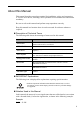
About this Manual This manual describes procedures required for installation, wiring, and connecting Σ-V Series servo drives, including a JOG operation for servomotors not connected to machinery. Be sure to refer to this manual and perform setup operations correctly. Keep this manual in a location where it can be accessed for reference whenever required. Description of Technical Terms The following table shows the meanings of terms used in this manual.
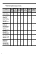
Manuals Related to the Σ-V Series Refer to the following manuals as required.
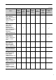
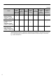
Name Selecting Ratings Models System and and Specifi- Design Peripheral cations Devices Σ-V Series User’s Manual MECHATROLINK-III Command (SIEP S800000 63) (Will be available soon.
Name Selecting Ratings Models System and and Specifi- Design Peripheral cations Devices (cont’d) Trial Panels Operation Maintenance Trial and and and Operation Wiring Inspection Servo Adjustment Σ-V Series Indexer Module Installation Guide (TOBP C720829 02) 9 9 9 Σ-V Series Feedback Option Module Installation Guide (TOBP C720829 03) 9 9 9 Σ Series Digital Operator Safety Precautions (TOBP C730800 00) 9 ∗ Refer to these manuals for troubleshooting of problems which may occur during setup.
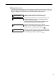
Safety Information The following conventions are used to indicate precautions in this manual. Failure to heed precautions provided in this manual can result in serious or possibly even fatal injury or damage to the products or to related equipment and systems. WARNING CAUTION PROHIBITED Indicates precautions that, if not heeded, could possibly result in loss of life or serious injury.
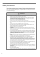
Safety Precautions These safety precautions are very important. Read them before performing any procedures such as checking products on delivery, storage and transportation, installation, wiring, operation and inspection, or disposal. Be sure to always observe these precautions thoroughly. WARNING • Never touch any rotating motor parts while the motor is running. Failure to observe this warning may result in injury.
WARNING • Provide an appropriate braking device on the machine side to ensure safety. The holding brake on a servomotor with a brake is not a braking device for ensuring safety. Failure to observe this warning may result in injury. • Do not come close to the machine immediately after resetting a momentary power loss. The machine may restart unexpectedly. Take appropriate measures to ensure safety against an unexpected restart. Failure to observe this warning may result in injury.
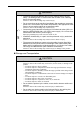
Storage and Transportation (cont’d) CAUTION • If disinfectants or insecticides must be used to treat packing materials such as wooden frames, pallets, or plywood, the packing materials must be treated before the product is packaged, and methods other than fumigation must be used. Example: Heat treatment, where materials are kiln-dried to a core temperature of 56°C for 30 minutes or more.
Wiring CAUTION • Be sure to wire correctly and securely. Failure to observe this caution may result in motor overrun, injury, or malfunction. • Do not connect a commercial power supply to the U, V, or W terminals for the servomotor connection. Failure to observe this caution may result in injury or fire. • Securely connect the main circuit power supply terminals and servomotor connection terminals. Failure to observe this caution may result in fire.
Wiring (cont’d) CAUTION • Do not reverse the polarity of the battery when connecting it. Failure to observe this caution may result in damage to the battery, the SERVOPACK, or cause an explosion. • Wiring or inspection must be performed by a technical expert. • Use a 24 VDC power supply with double insulation or reinforced insulation. • Failures caused by incorrect wiring or wrong voltage application in the brake circuit may damage the equipment or cause an accident resulting in death or injury.
Operation (cont’d) CAUTION • When using JOG operations (Fn002) origin search operations (Fn003), or EasyFFT operations (Fn206), the dynamic brake function does not work for reverse overtravel or forward overtravel. Take necessary precautions. Failure to observe this caution may result in damage to the product. • When using the servomotor for a vertical axis, install safety devices to prevent workpieces from falling due to alarms or overtravels.
Maintenance and Inspection CAUTION • Do not disassemble the SERVOPACK. Failure to observe this caution may result in electric shock or injury. • Do not attempt to change wiring while the power is ON. Failure to observe this caution may result in electric shock or injury. • When replacing the SERVOPACK, resume operation only after copying the previous SERVOPACK parameters to the new SERVOPACK. Failure to observe this caution may result in damage to the product.
Warranty (1) Details of Warranty Period of Warranty The period of warranty for a product that was purchased (hereafter “delivered product”) is one year from the time of delivery to the location specified by the customer or 18 months from the time of shipment from the Yaskawa factory, whichever is sooner. Scope of Warranty Yaskawa shall replace or repair a defective product free of change if a defect attributable to Yaskawa occurs during the period of warranty above.
(3) Suitability for Use 1. It is the customer’s responsibility to confirm conformity with any standards, codes, or regulations that apply if the Yaskawa product is used in combination with any other products. 2. The customer must confirm that the Yaskawa product is suitable for the systems, machines, and equipment used by the customer. 3. Consult with Yaskawa to determine whether use in the following applications is acceptable.
Applicable Standards North American Safety Standards (UL) UL∗ Standards (UL File No.) Model SERVOPACK • SGDV UL508C (E147823) Servomotor • • • • • UL1004 (E165827) SGMJV SGMAV SGMPS SGMGV SGMSV ∗ Underwriters Laboratories Inc.
CONTENTS About this Manual . . . . . . . . . . . . . . . . . . . . . . . . . . . . . . . . . . . . . . . . . . . . . . . . . iii Safety Precautions . . . . . . . . . . . . . . . . . . . . . . . . . . . . . . . . . . . . . . . . . . . . . . . viii Warranty . . . . . . . . . . . . . . . . . . . . . . . . . . . . . . . . . . . . . . . . . . . . . . . . . . . . . . . xv Applicable Standards . . . . . . . . . . . . . . . . . . . . . . . . . . . . . . . . . . . . . . . . . . . . . xvii 1 Overview of Setup . . .
4 Safety Function . . . . . . . . . . . . . . . . . . . . . . . . . . . . . . . . . . . . . . . . . . 4-1 4.1 4.2 4.3 4.4 4.5 Outline . . . . . . . . . . . . . . . . . . . . . . . . . . . . . . . . . . . . . . . . . . . . . . . . . . . . . . . . . . . . . Hard Wire Base Block (HWBB) Function . . . . . . . . . . . . . . . . . . . . . . . . . . . . . . . . . . . Safety Function Signal (CN8) Names and Functions . . . . . . . . . . . . . . . . . . . . . . . . . Precautions When Not Using the Safety Function .
1 Overview of Setup Overview of Setup This chapter describes how to set up the Σ-V series of servo drives.
1 Overview of Setup This chapter describes the flow of the setup procedure from installation until a JOG operation. A panel operator, a digital operator, and SigmaWin+, (which is an engineering tool that can be used with a PC) are available to set up a servo drive. The panel operator is included with the SERVOPACK of analog pulse models, and the digital operator and SigmaWin+ are sold separately.
2 Installation This chapter describes how to install the servomotor and the SERVOPACK. 2.1 Installation Environment and Applicable Standards . . . . . . . . . 2-2 2.1.1 Servomotor Installation Environment . . . . . . . . . . . . . . . . . . . . . . 2-2 2.1.2 SERVOPACK Installation Environment . . . . . . . . . . . . . . . . . . . . 2-3 2.1.3 Installation Conditions for Applicable Standards . . . . . . . . . . . . . . 2-4 2.2 Servomotor Installation . . . . . . . . . . . . . . . . . . . . . . . . . . . . .
2 Installation 2.1.1 Servomotor Installation Environment 2.1 Installation Environment and Applicable Standards The installation environment and the applicable standards for servomotors and SERVOPACKs are described in this section. 2.1.
2.1 Installation Environment and Applicable Standards SERVOPACK Installation Environment Surrounding air temperature: 0 to 55°C Ambient humidity: 90% RH or less (with no condensation) Altitude: 1,000 m or less Vibration resistance: 4.9 m/s2 Shock resistance: 19.6 m/s2 Installation Precautions • Mounting in a Control Panel To prevent the temperature around the SERVOPACK from exceeding 55°C, take into account the size of the control panel, the layout of the SERVOPACK, and the cooling method.
2 Installation 2.1.3 Installation Conditions for Applicable Standards 2.1.
2.2 Servomotor Installation 2.2 Servomotor Installation 2.2.1 Orientation Servomotors can be installed either horizontally or vertically. Servomotors with gears can be installed only horizontally, depending on gear lubrication conditions. Refer to Σ-V Series Product Catalog (KAEP S800000 42) for details.
2 Installation 2.2.3 Connecting Servomotor to Machine 2.2.3 Connecting Servomotor to Machine The end of the motor shaft is coated with anticorrosive paint. Thoroughly remove the paint prior to installation. Align the shaft of the servomotor with the shaft of the machine, and then couple the shafts. Install the servomotor so that alignment accuracy falls within the following range. Vibration will damage the bearings or encoders if the shafts are not properly aligned.
2.2 Servomotor Installation Protective Structure The servomotor protective structure* is described below. Model Without Gears With Gears IP65 IP55 SGMPS IP55 IP67 (Optional) IP55 SGMGV IP67 − SGMSV IP67 (SGMSV-70 servomotor only: IP22) − SGMCS-02 to -35 IP42 (expect for gaps on the rotating section of the shaft) − SGMCS-45 to -2Z IP44 − SGMJV, SGMAV ∗ Except through shaft section. The protective structure specifications can be satisfied only when using a specified cable.
2 Installation 2.2.5 Other Precautions 2.2.5 Other Precautions Handling Oil and Water If the servomotor is used in a location that is subject to water or oil mist, use a servomotor with an oil seal to seal the through shaft section. Precautions on using a servomotor with an oil seal are described below. • Put the oil surface under the oil seal lip. • Use an oil seal in favorably lubricated condition.
2.3 SERVOPACK Installation 2.3 SERVOPACK Installation 2.3.1 Orientation The SERVOPACK is available in models that are base-mounted, models that are rack-mounted, and models that are duct-ventilated. In any case, mount the SERVOPACK with a vertical orientation. Firmly secure the SERVOPACK to the mounting surface, using either two or four mounting holes depending on the SERVOPACK capacity.
2 Installation 2.3.2 Installation Standards • Duct-ventilated Duct Air Flow 2.3.2 Installation Standards Observe the standards for mounting SERVOPACKs in control panels, including those for the mounting SERVOPACKs side by side in one control panel as shown in the following illustration. Note: For SERVOPACKs of command option attachable type, installation conditions may differ depending on the attached option module. For details, refer to the user’s manual for each option module.
2.3 SERVOPACK Installation • Mounting SERVOPACKs Side by Side in a Control Panel Fan 30 mm or more Fan 40 mm or more Width varies with SERVOPACK model 40 mm or more Leave sufficient space on each side and at the top and the bottom of each SERVOPACK. The width on each side varies in accordance with the models of the SERVOPACKS used.
2 Installation 2.4.1 SGDV-01A (Analog Pulse Model) 2.4 EMC Installation Conditions This section describes the recommended installation conditions that satisfy EMC guidelines for each model of the SGDV SERVOPACK. The conditions required for the standard type (base-mounted) of SERVOPACK are described. Refer to this section for other SERVOPACK models such as the rack-mounted types as well. This section describes the EMC installation conditions satisfied in test conditions prepared by Yaskawa.
2.
2 Installation 2.4.
2.
2 Installation 2.4.
2.4 EMC Installation Conditions Three-phase 400 V • SGDV-D01A ( = 1R9, 3R5, 5R4, 8R4, 120, 170) CN1 CN8 Core Core Clamp Clamp 1 2 Host controller Symbol ∗3.
2 Installation 2.4.1 SGDV-01A (Analog Pulse Model) Three-phase 400 V • SGDV-D01A ( = 210, 260, 280, 370) Brake Power Supply Noise filter*2 Power supply: Three-phase 400 VAC 6 Clamp SERVOPACK Control power supply 24 VDC*1 24 V, 0 V Noise filter*3 U, V, W L1, L2, L3 CN2 Surge absorber Regenerative resistor unit cable PE CN1 CN8 Clamp Clamp 1 ∗1. ∗2. ∗3.
2.
2 Installation 2.4.
2.
2 Installation 2.4.
2.
2 Installation 2.4.
2.4 EMC Installation Conditions Three-phase 400 V • SGDV-D11A ( = 210, 260, 280, 370) Brake Power Supply 6 Control power supply 24 VDC*1 Noise filter*3 SERVOPACK 24 V, 0 V U, V, W 3 L1, L2, L3 CN2 Surge absorber 7 Regenerative resistor cable MECHATROLINK-II controller 8 Clamp PE Encoder 4 CN6A, CN6B CN1 CN8 Clamp Clamp 1 Symbol ∗3. Servomotor B1, B2 Host controller ∗1. ∗2.
2 Installation 2.4.3 SGDV-21A (M-III Model) 2.4.
2.
2 Installation 2.4.
2.
2 Installation 2.4.
2.
2 Installation 2.4.3 SGDV-21A (M-III Model) Three-phase 400 V • SGDV-D21A ( = 210, 260, 280, 370) Brake Power Supply 6 Power supply: Three-phase 400 VAC 7 1 Symbol 2-32 Clamp Clamp Servomotor Encoder 4 CN6A, CN6B CN1 Host controller ∗3. Brake B1, B2 Clamp ∗1. ∗2.
2.4 EMC Installation Conditions 2.4.4 SGDV-E1A (Command Option Attachable Type) For SERVOPACKs of command option attachable type, EMC installation conditions may differ depending on the attached option module. For details, refer to the user’s manual for each option module.
3 Wiring and Connection This chapter describes how to set up the wiring and connections required for trial operation. For more information on the wiring and connection, refer to the following manuals.
3 Wiring and Connection 3.1 Precautions for Wiring CAUTION • Be sure to wire correctly and securely. Failure to observe this caution may result in motor overrun, injury, or malfunction. • Do not bundle or run the main circuit cables together with the I/O signal cables or the encoder cables in the same duct. Keep them separated by at least 30 cm. Failure to do so may result in malfunction.
3.2 System Configuration Diagram 3.2 System Configuration Diagram 3.2.1 Connecting to SGDV-01A SERVOPACK (Analog Pulse Model) SGDV-F01A Power supply Single-phase 100 VAC R T Molded-case circuit breaker (MCCB) Protects the power supply line by shutting the circuit OFF when overcurrent is detected. Digital operator SGDV- F01A SERVOPACK Noise filter Used to eliminate external noise from the power line. Magnetic contactor Turns the servo ON and OFF. Install a surge absorber.
3 Wiring and Connection 3.2.1 Connecting to SGDV-01A SERVOPACK (Analog Pulse Model) SGDV-A01A • Using a Three-phase, 200-V Power Supply Power supply Three-phase 200 VAC R S T Molded-case circuit breaker (MCCB) Protects the power supply line by shutting the circuit OFF when overcurrent is detected. Noise filter SGDV- A01A SERVOPACK Used to eliminate external noise from the power line. Digital operator Magnetic contactor Turns the servo ON and OFF. Install a surge absorber.
3.2 System Configuration Diagram • Using a Single-phase, 200-V Power Supply The Σ-V Series SERVOPACK for a 200-V power supply input has input specifications for a three-phase power supply, but some models can also be used with a singlephase 200-V power supply. For details, refer to Σ-V Series User's Manual Design and Maintenance Rotational Motor/Analog Voltage and Pulse Train Reference (SIEP S800000 45).
3 Wiring and Connection 3.2.1 Connecting to SGDV-01A SERVOPACK (Analog Pulse Model) SGDV-D01A Power supply Three-phase 400 VAC RST Molded-case circuit breaker (MCCB) Protects the power supply line by shutting the circuit OFF when overcurrent is detected. Noise filter Used to eliminate external noise from the power line. Magnetic contactor Turns the servo ON and OFF. Install a surge absorber.
3.2 System Configuration Diagram 3.2.2 Connecting to SGDV-11A SERVOPACK (M-II Model) SGDV-F11A Power supply Single-phase 100 VAC R T Molded-case circuit breaker (MCCB) Protects the power supply line by shutting the circuit OFF when overcurrent is detected. Noise filter Used to eliminate external noise from the power line. Magnetic contactor SGDV- F11A SERVOPACK Digital operator Turns the servo ON and OFF. Install a surge absorber.
3 Wiring and Connection 3.2.2 Connecting to SGDV-11A SERVOPACK (M-II Model) SGDV-A11A • Using a Three-phase, 200-V Power Supply Power supply Three-phase 200 VAC R S T Molded-case circuit breaker (MCCB) Protects the power supply line by shutting the circuit OFF when overcurrent is detected. Connect to the MECHATROLINK-II SGDV- A11A SERVOPACK Noise filter Used to eliminate external noise from the power line. Digital operator Magnetic contactor Turns the servo ON and OFF.
3.2 System Configuration Diagram • Using a Single-phase, 200-V Power Supply The Σ-V Series SERVOPACK for a 200-V power supply input has input specifications for a three-phase power supply, but some models can also be used with a singlephase 200-V power supply. For details, refer to Σ-V Series User's Manual Design and Maintenance Rotational Motor/MECHATROLINK-II Communications Reference (SIEP S800000 46).
3 Wiring and Connection 3.2.2 Connecting to SGDV-11A SERVOPACK (M-II Model) SGDV-D11A Power supply Three-phase 400 VAC RST Molded-case circuit breaker (MCCB) Protects the power supply line by shutting the circuit OFF when overcurrent is detected. Noise filter Used to eliminate external noise from the power line. SGDV- D11A SERVOPACK Magnetic contactor Connect to the MECHATROLINK-II Personal computer Connection cable for digital operator Turns the servo ON and OFF.
3.2 System Configuration Diagram 3.2.3 Connecting to SGDV-21A SERVOPACK (M-III Model) SGDV-F21A Power supply Single-phase 100 VAC R T Molded-case circuit breaker (MCCB) Protects the power supply line by shutting the circuit OFF when overcurrent is detected. Noise filter Used to eliminate external noise from the power line. SGDV- F21A SERVOPACK Magnetic contacator Turns the servo ON and OFF. Install a surge absorber. Digital operator Connect to the MECHATROLINK-III.
3 Wiring and Connection 3.2.3 Connecting to SGDV-21A SERVOPACK (M-III Model) SGDV-A21A • Using a Three-phase, 200-V Power Supply Power supply Three-phase 200 VAC R S T Molded-case circuit breaker (MCCB) Protcts the power supply line by shutting the circuit OFF when overcurrent is detected. Noise filter Used to eliminate external noise from the power line. SGDV- A21A SERVOPACK Connect to the MECHATROLINK-III. Magnetic contactor Turns the servo ON and OFF. Install a surge absorber.
3.2 System Configuration Diagram • Using a Single-phase, 200-V Power Supply The Σ-V Series SERVOPACK for a 200-V power supply input has input specifications for a three-phase power supply, but some models can also be used with a singlephase 200-V power supply. For details, refer to Σ-V Series User's Manual Design and Maintenance Rotational Motor/MECHATROLINK-III Communications Reference (SIEP S800000 64).
3 Wiring and Connection 3.2.3 Connecting to SGDV-21A SERVOPACK (M-III Model) SGDV-D21A Power supply Three-phase 400 VAC RST Molded-case circuit breaker MCCB) Protects the power supply line by shutting the circuit OFF when overcurrent is detected. Noise filter Used to eliminate external noise from the power line. Connect to the MECHATROLINK-III. SGDV- D21A SERVOPACK Magnetic contactor Personal computer Connection cable for digital operator Turns the servo ON and OFF.
3.2 System Configuration Diagram 3.2.4 Connecting to SGDV-E1A SERVOPACK (Command Option Attachable Type) SGDV-FE1A Power supply Single-phase 100 VAC R T Molded-case circuit breaker (MCCB) Protects the power supply line by shutting the circuit OFF when overcurrent is detected. Noise filter Used to eliminate external noise from the power line. SGDV- FE1A SERVOPACK Digital operator Option module*3 Magnetic contactor Turns the servo ON and OFF. Install a surge absorber.
3 Wiring and Connection 3.2.4 Connecting to SGDV-E1A SERVOPACK (Command Option Attachable Type) SGDV-AE1A • Using a Three-phase, 200-V Power Supply Power supply Three-phase 200 VAC R S T Molded-case circuit breaker (MCCB) Protects the power supply line by shutting the circuit OFF when overcurrent is detected. Noise filter Used to eliminate external noise from the power line. SGDV- AE1A SERVOPACK Digital operator Option module*3 Magnetic contactor Turns the servo ON and OFF.
3.2 System Configuration Diagram • Using a Single-phase, 200-V Power Supply The Σ-V Series SERVOPACK for a 200-V power supply input has input specifications for a three-phase power supply, but some models can also be used with a singlephase 200-V power supply. For details, refer to Σ-V Series User’s Manual Design and Maintenance Rotational Motor/Command Option Attachable Type (SIEP S800000 60).
3 Wiring and Connection 3.2.4 Connecting to SGDV-E1A SERVOPACK (Command Option Attachable Type) SGDV-DE1A Power supply Three-phase 400 VAC RST Molded-case circuit breaker (MCCB) Protects the power supply line by shutting the circuit OFF when overcurrent is detected. Noise filter Used to eliminate external noise from the power line. SGDV- DE1A SERVOPACK Digital operator Option module *4 Personal computer Magnetic contactor Turns the servo ON and OFF. Install a surge absorber.
3.3 Main Circuit Wiring 3.3 Main Circuit Wiring The names, specifications, and functions of the main circuit terminals required for trial operation are given below. 3.3.
3 Wiring and Connection 3.3.2 SERVOPACK Main Circuit Wire Size (cont’d) Name Terminal Symbols Model SGDV- Description If the regenerative capacity is insufR70F, R90F, 2R1F, 2R8F, ficient, connect an external regenerR70A, R90A, 1R6A, ative resistor (option) between B1/ 2R8A and B2.
3.3 Main Circuit Wiring Wire Types Use the following type of wire for main circuit. Cable Type Symbol Allowable Conductor Temperature °C Name IV 600 V polyvinyl chloride insulated wire 60 HIV 600 V grade heat-resistant polyvinyl chloride insulated wire 75 The following table shows the wire sizes and allowable currents for three wires. Use wires with specifications equal to or less than those shown in the table.
3 Wiring and Connection 3.3.2 SERVOPACK Main Circuit Wire Size Single-phase, 100 V External Terminal Name Main circuit power input terminals SERVOPACK Model SGDV- Terminal Symbols R70 L1, L2 Control power input terminals Servomotor connection terminals External regenerative resistor connection terminals R90 2R1 HIV1.25 HIV2.0 L1C, L2C HIV1.25 U, V, W HIV1.25 B1/ 2R8 HIV1.25 , B2 Ground terminal HIV2.
3.3 Main Circuit Wiring Three-phase, 400 V Main circuit power input terminals Terminal Symbols L1, L2, L3 Control power input terminals 24V, 0V Servomotor connection terminals U, V, W External regenerative resistor connection terminals B1/ , B2 (B1, B2) Ground terminal SERVOPACK Model SGDV1R9 3R5 5R4 8R4 120 170 210 260 280 370 HIV1.25 HIV2.0 HIV3.5 HIV HIV HIV 5.5 8.0 14.0 HIV1.25 HIV1.25 HIV1.25 HIV2.0 HIV 3.5 HIV5.5 HIV HIV 8.0 14.0 HIV 2.0 HIV3.5 HIV HIV 5.5 8.0 HIV2.
3 Wiring and Connection 3.3.3 Typical Main Circuit Wiring Examples 3.3.3 Typical Main Circuit Wiring Examples • Use a molded-case circuit breaker (1QF) or fuse to protect the main circuit. The SERVOPACK connects directly to a commercial power supply; it is not isolated through a transformer or other device. Always use a molded-case circuit breaker (1QF) or fuse to protect the servo system from accidents involving different power system voltages or other accidents. • Install a ground fault detector.
3.
3 Wiring and Connection 3.3.
3.3 Main Circuit Wiring Precautions When Using More Than One SERVOPACK This section shows an example of the wiring when more than one SERVOPACK is used and the precautions. • Wiring Example (Analog pulse model) Connect the alarm output (ALM) terminals for the three SERVOPACKs in series to enable alarm detection relay 1RY to operate. When the alarm occurs, the ALM output signal transistor is turned OFF.
3 Wiring and Connection 3.3.4 Wiring the Main Circuit Terminal Connector (Spring Type) • Precautions When using more than one SERVOPACK with a DC power supply, refer to these manuals here for the appropriate wiring, connections, and required settings.
3.3 Main Circuit Wiring Wiring Procedure 1. Remove the main circuit terminal connector from the SERVOPACK. Enlarged View 1㧚Press the lock. Lock 2. 2. Remove the main circuit terminal connector while pressing the lock. Main circuit terminal connector Strip the end of the wires. Applicable wire sizes: Refer to 3.3.2 SERVOPACK Main Circuit Wire Size. 8 to 9 mm 3. Open the wire terminal on the terminal connector housing with a tool, using the following methods.
3 Wiring and Connection 3.3.4 Wiring the Main Circuit Terminal Connector (Spring Type) Using a screwdriver Use a commercially available flat-blade screwdriver with a blade width of 3.0 to 3.5 mm. Insert the screwdriver into the slot and press down firmly to open the wire terminal. 4. 5. 6. 3-30 Insert the wire core into the opening, and then secure the wire into position by removing the opener or screwdriver to close the opening. Make all the required connections in the same way.
3.4 Connecting Regenerative Resistors 3.4 Connecting Regenerative Resistors This section describes how to connect regenerative resistors and set the regenerative resistor capacity. To learn how to select a regenerative resistor, and for detailed specifications, refer to Σ-V Series Product Catalog (KAEP S800000 42). For more information on how to set the capacity of regenerative resistors, refer to Σ-V Series User’s Manual Design and Maintenance (SIEP S800000 45/46/60/64).
3 Wiring and Connection 3.4.1 Connecting Regenerative Resistor SERVOPACKs: Model SGDV-3R8A, 5R5A, 7R6A, 120A, 180A, 200A, 330A, 1R9D, 3R5D, 5R4D, 8R4D, 120D, 170D Disconnect the wiring between the SERVOPACK’s B2 and B3 terminals and connect an external regenerative resistor between the B1/ and B2 terminals or between the B1 and B2 terminals. Note: Be sure to take out the lead wire between the B2 and B3 terminals.
3.4 Connecting Regenerative Resistors SERVOPACKs: Model SGDV-470A, 550A, 590A, 780A, 210D, 260D, 280D, 370D No built-in regenerative resistor is provided, so the external regenerative resistor is required. The regenerative resistor units are as follow: Main Circuit Power Supply Threephase 200 V Threephase 400 V Applicable SERVOPACK Model SGDV Applicable Regenerative Resistor Unit Resistance (Ω) Specifications 470A JUSP-RA04-E 6.
4 Safety Function This chapter describes the safety functions. 4.1 Outline . . . . . . . . . . . . . . . . . . . . . . . . . . . . . . . . . . . . . . . . . . . . 4-2 4.2 Hard Wire Base Block (HWBB) Function . . . . . . . . . . . . . . . . . 4-3 4.3 Safety Function Signal (CN8) Names and Functions . . . . . . . . 4-4 4.4 Precautions When Not Using the Safety Function . . . . . . . . . . 4-4 Safety Function 4.5 When Using the Safety Function . . . . . . . . . . . . . . . . . . . . . . .
4 Safety Function 4.1 Outline The safety function is incorporated in the SERVOPACK to reduce the risk associated with the machine by protecting workers from injury and by securing safe machine operation. Especially when working in hazardous areas inside the safeguard, as for machine maintenance, it can be used to avoid adverse machine movement.
4.2 Hard Wire Base Block (HWBB) Function Hard Wire Base Block (HWBB) Function The Hard Wire Base Block function (hereinafter referred to as HWBB function) is a safety function designed to baseblock the motor (shut off the motor current) by using the hardwired circuits: Each circuit for two channel input signals blocks the run signal to turn off the power module, and the motor current is shut off. (Refer to the diagram below.
4 Safety Function 4.3 Safety Function Signal (CN8) Names and Functions The following table shows the terminal layout of safety function signals (CN8). Signal Name Pin No.
4.5 When Using the Safety Function When Using the Safety Function Connect a safety device using the following procedure. 1. Remove the servomotor connection terminal connector while pressing the lock. Enlarged View 1. Press the lock. Lock 2. Servomotor connection terminal connector 2. Remove the servomotor connection terminal connector while pressing the lock.
4 Safety Function 3. Connect a safety device to CN8. Note: When not using the safety function, use the SERVOPACK with the safety function jumper connector inserted in CN8. If the SERVOPACK is used without the jumper connector inserted into CN8, no current will flow to the motor and no torque will be output. In this case, "Hbb" will be displayed on the Panel Operator or the Digital Operator.
5 Trial Operation (Checking Servomotor Operation) This chapter describes how to perform trial operation. 5.1 Outline . . . . . . . . . . . . . . . . . . . . . . . . . . . . . . . . . . . . . . . . . . . . 5-2 5.2 Inspection and Checking before Trial Operation . . . . . . . . . . . . 5-2 5.3 JOG Operation Using a Panel Operator . . . . . . . . . . . . . . . . . . 5-5 5.4 JOG Operation Using a Digital Operator . . . . . . . . . . . . . . . . . . 5-7 Trial Operation (Checking Servomotor Operation) 5.
5 Trial Operation (Checking Servomotor Operation) 5.1 Outline The trial operation described here is a JOG operation for servomotors not connected to machinery (without a load). The purpose of this trial operation is to check whether the SERVOPACK and servomotor are properly connected and whether the servomotor is operating normally. To conduct trial operation executed from the host controller for the servomotor without load, or for the servomotor connected to the machine, refer to the following manuals.
5.2 Inspection and Checking before Trial Operation An example of the circuit wiring Servomotor with brake SERVOPACK Power supply L1 L2 L3 L1C U V W M L2C CN2 ENC BK 24 VDC power supply or Brake power supply AC DC 24 VDC or 90 VDC A 24 VDC power supply is not included. Brake power supply Input voltage of 200 V: LPSE-2H01-E Input voltage of 100 V: LPDE-1H01-E Configure the relay circuit to apply the holding brake by the emergency stop.
5 Trial Operation (Checking Servomotor Operation) Installing the Servomotor and SERVOPACK Install the servomotor and SERVOPACK according to the installation conditions. Secure the mounting plate of the servomotor to the equipment. Do not connect any load to the shaft. • Be sure to secure the servomotor to the equipment, or the servomotor may turn over when it starts rotating. • Do not connect anything to the servomotor shaft.
5.3 JOG Operation Using a Panel Operator 5.3 JOG Operation Using a Panel Operator This section describes the procedure for executing a JOG operation using a panel operator. The panel operator is located under the front cover of the SERVOPACK (analog pulse models only). View with front cover open Panel operator 1 Display after operation Keys Operation Turn ON the power to the SERVOPACK. The forward run prohibited (P-OT) or reverse run prohibited (N-OT) message is displayed.
5 Trial Operation (Checking Servomotor Operation) (cont’d) Step Display after operation Keys Operation Press the Up Cursor Key to rotate the servomotor in the forward direction and press the Down Cursor Key to rotate it in reverse. The servomotor will operate while the key is being pressed. (The factory setting is 500 min-1.) Forward rotation 6 MODE/SET DATA/ Reverse rotation Confirm that the servomotor operation is correct.
5.4 JOG Operation Using a Digital Operator 5.4 JOG Operation Using a Digital Operator This section describes the procedure for executing a JOG operation using a digital operator. Connect the digital operator to the SERVOPACK CN3 connector. Σ-V series JUSP-OP05A-1-E Digital Operator Σ-III series JUSP-OP05A Digital Operator SGDV SERVOPACK Digital operator conversion conneotor Model: JZSP-CVS05-A3-E The digital operator can be connected or removed while the SERVOPACK power is ON.
5 Trial Operation (Checking Servomotor Operation) (cont’d) Step Display after operation −JOG− 04=00500 00=000000 02=000000 0D=00000000000 3 B P U U U B n3 n0 n0 n0 4 R P U U U UN −JOG− n304=00500 n000=000000 n002=000000 n00D=00000000000 Keys Operation Press the Key. The display changes to the execution display of Fn002. Press the Key. "RUN" is displayed as the status, and the servomotor power turns ON.
5.4 JOG Operation Using a Digital Operator (cont’d) Step Display after operation 8 㧮㧮ޓޓޓޓޓޓ㧙㧼㧾㧹㧛㧹㧻㧺㧙 㨁㨚㧜㧜㧜㧩 㧜㧜㧜㧜㧜 㨁㨚㧜㧜㧞㧩 㧜㧜㧜㧜㧜 㨁㨚㧜㧜㧤㧩 㧜㧜㧜㧜㧜㧜㧜㧜㧜㧜 㨁㨚㧜㧜㧰㧩 㧜㧜㧜㧜㧜㧜㧜㧜㧜㧜 Keys Operation Press the Key twice to return to the initial display (step 1). Alarm Display An alarm is automatically displayed if a problem occurs for some reason.
5 Trial Operation (Checking Servomotor Operation) 5.5 JOG Operation Using SigmaWin+ This section describes the procedure for executing a JOG operation using SigmaWin+. In the following example, test-run procedures are explained using the JOG operation window of Test Run on the main menu of SigmaWin+. Step Operation Display • Connect a computer. Use a connection cable to connect a SERVOPACK to a computer which has SigmaWin+ installed.
5.5 JOG Operation Using SigmaWin+ (cont’d) Step Operation Display (5) Once SigmaWin+ is started, the connection window is displayed. Note: is used for operation with no SERVOPACK connected. Click to search for the connected SERVOPACK. Connection Window Select only Σ-V Search Condition Setting Window (7) Select the SERVOPACK to be connected. Click . (Place the cursor over the SERVOPACK to be connected, and then click on it.) The main window of SigmaWin+ will then open.
5 Trial Operation (Checking Servomotor Operation) (cont’d) Step Operation • Run test operation. (1) Select Test Run first, and then select Jog (J) from the menu on the main window. Display Test Run (R) → Jog (J) Main Window (2) Warnings for the JOG operation window will be displayed. Read them and click . 3 Warnings for the JOG Operation Window (3) The JOG operation window is open.
5.5 JOG Operation Using SigmaWin+ (cont’d) Step Operation Display • Set the JOG speed The motor speed is set to 500 [min-1]. Click if you need to change it. 4 • Servo ON Click . The display changes from Servo OFF to Servo ON and is lit in green.
5 Trial Operation (Checking Servomotor Operation) (cont’d) Step Operation Display • Start JOG operation. When you click the servomotor will rotate in the forward direction. When 6 you click it will rotate in reverse. Confirm that the servomotor operation is correct. At the same time, carefully inspect the servomotor’s condition and check the following points in particular. If a problem is found, correct it.
Revision History The revision dates and numbers of the revised manuals are given at the bottom of the back cover. MANUAL NO. SIEP S800000 43B Published in Japan November 2008 07- 4 1 Date of publication Date of Publication April 2007 November 2008 Rev. No. Section – 1 2 Revised Contents First edition All chapters Completely revised Back Cover Revision: Address – June 2009 Revison number Date of original publication Based on Japanese user’s manual, SIJPS80000043F<5> published in May 2009.
英文 No.9-5(A5) モーションコントロール事業部用 AC Servo Drives Σ -V Series USER'S MANUAL Setup Rotational Motor IRUMA BUSINESS CENTER (SOLUTION CENTER) 480, Kamifujisawa, Iruma, Saitama 358-8555, Japan Phone 81-4-2962-5696 Fax 81-4-2962-6138 YASKAWA ELECTRIC AMERICA, INC. 2121 Norman Drive South, Waukegan, IL 60085, U.S.A. Phone (800) YASKAWA (800-927-5292) or 1-847-887-7000 Fax 1-847-887-7370 YASKAWA ELETRICO DO BRASIL LTDA.