Manual No. I63E-EN-01 Manual No. I63E-EN-01 VS mini J7 USER’S MANUAL OMRON YASKAWA MOTION CONTROL B.V. – Wegalaan 65 – 2132 JD Hoofddorp – The Netherlands phone: + 31 (0) 23 568 74 00 – fax: + 31 (0) 23 568 74 88 – www.omronyaskawa.com Note: Specifications subject to change without notice. Manual No.
Thank you for choosing this VARISPEED J7-series product. Proper use and handling of the product will ensure proper product performance, will lengthen product life, and may prevent possible accidents. Please read this manual thoroughly and handle and operate the product with care. 1. To ensure safe and proper use of the OMRON-YASKAWA Inverters, please read this USER’S MANUAL (Cat. No. I63-EN-01) to gain sufficient knowledge of the devices, safety information, and precautions before actual use. 2.
Notice OMRON-YASKAWA products are manufactured for use according to proper procedures by a qualified operator and only for the purposes described in this manual. The following conventions are used to indicate and classify precautions in this manual. Always heed the information provided with them. Failure to heed precautions can result in injury to people or damage to property. ! DANGER Indicates an imminently hazardous situation which, if not avoided, will result in death or serious injury.
General Precautions Observe the following precautions when using the VARISPEED Inverters and peripheral devices. This manual may include illustrations of the product with protective covers removed in order to describe the components of the product in detail. Make sure that these protective covers are on the product before use. Consult your OMRON-YASKAWA representative when using the product after a long period of storage. ! WARNING ! WARNING Do not touch the inside of the Inverter.
Transportation Precautions ! Caution Do not hold by front cover or panel , instead, hold by the radiation fin (heat sink) while transporting the product. Doing so may result in injury. ! Caution Do not pull on the cables. Doing so may result in damage to the product or malfunction. ! Caution Use the eye-bolts only for transporting the Inverter. Using them for transporting the machinery may result in injury or malfunction.
Operation and Adjustment Precautions ! WARNING Turn ON the input power supply only after mounting the front cover, terminal covers, bottom cover, Operator, and optional items. Not doing so may result in electrical shock. ! WARNING Do not remove the front cover, terminal covers, bottom cover, Operator, or optional items while the power is being supplied. Doing so may result in electrical shock or damage to the product. ! WARNING Do not operate the Operator or switches with wet hands.
Maintenance and Inspection Precautions ! WARNING ! WARNING Do not touch the Inverter terminals while the power is being supplied. Maintenance or inspection must be performed only after turning OFF the power supply, confirming that the CHARGE indicator (or status indicators) is turned OFF, and after waiting for the time specified on the front cover. Not doing so may result in electrical shock. ! WARNING Maintenance, inspection, or parts replacement must be performed by authorized personnel.
Contents of Warning • For CIMR-J7AZ20P1 to 20P7 (0.1 to 0.75 kW) and CIMR-J7AZB0P1 to B0P4 (0.1 to 0.4 kW): • For CIMR-J7AZ21P5 to A4P0 (1.5 to 4.0 kW), CIMR-J7AZB0P7 to B1P5 (0.75 to 1.5 kW), and CIMR-J7AZ40P2 to 44P0 (0.2 to 3.7 kW): Checking Before Unpacking Checking the Product On delivery, always check that the delivered product is the VARISPEED J7 Inverter that you ordered. Should you find any problems with the product, immediately contact your nearest local sales representative.
Maximum Applicable Motor Capacity 0P1 0P2 0P4 0P7 1P5 2P2 4P0 0.1 (0.1) kW 0.25/0.37 (0.2) kW 0.55 (0.4) kW 1.1 (0.75) kW 1.5 (1.5) kW 2.2 (2.2) kW 4.0 (4.0) kW Note The figures in parentheses indicate capacities for motors used outside Japan. Voltage Class 2 B 4 Three-phase 200-V AC input (200-V class) Single-phase 200-V AC input (200-V class) Three-phase 400-V AC input (400-V class) Checking for Damage Check the overall appearance and check for damage or scratches resulting form transportation.
Warranty and Limitations of Liability WARRANTY OMRON-YASKAWA’s exclusive warranty is that the products are free from defects in materials and workmanship for a period of one year (or other period if specified) from date of sale by OMRON-YASKAWA. OMRON-YASKAWA MAKES NO WARRANTY OR REPRESENTATION, EXPRESS OR IMPLIED, REGARDING NONINFRINGEMENT, MERCHANTABILITY, OR FITNESS FOR PARTICULAR PURPOSE OF THE PRODUCTS.
Disclaimers CHANGE IN SPECIFICATIONS Product specifications and accessories may be changed at any time based on improvements and other reasons. It is our practice to change model numbers when published ratings or features are changed, or when significant construction changes are made. However, some specifications of the products may be changed without any notice. When in doubt, special model numbers may be assigned to fix or establish key specifications for your application on your request.
XII
Table of Contents CHAPTER 1 Overview. . . . . . . . . . . . . . . . . . . . . . . . . . . . . . . . . . . . . . 1 1-1 Function . . . . . . . . . . . . . . . . . . . . . . . . . . . . . . . . . . . . . . . . . . . . . . . . . . . . . . . . 2 1-2 Nomenclature. . . . . . . . . . . . . . . . . . . . . . . . . . . . . . . . . . . . . . . . . . . . . . . . . . . . 3 CHAPTER 2 Design . . . . . . . . . . . . . . . . . . . . . . . . . . . . . . . . . . . . . . . . 5 2-1 Installation . . . . . . . . . . . . . .
Table of Contents CHAPTER 7 Communications . . . . . . . . . . . . . . . . . . . . . . . . . . . . . . 89 7-1 RS-422/485 Communications Unit . . . . . . . . . . . . . . . . . . . . . . . . . . . . . . . . . . 90 7-2 Inverter Settings. . . . . . . . . . . . . . . . . . . . . . . . . . . . . . . . . . . . . . . . . . . . . . . . . 93 7-3 Message Communications Basic Format. . . . . . . . . . . . . . . . . . . . . . . . . . . . . . 98 7-4 DSR Message and Response . . . . . . . . . . . . . . . . . . . .
CHAPTER 1 Overview 1-1 Function . . . . . . . . . . . . . . . . . . . . . . . . . . . . . . . . . . . . . . . . . . . . . . . . . . . . . . 2 1-2 Nomenclature. . . . . . . . . . . . . . . . . . . . . . . . . . . . . . . . . . . . . . . . . . . . . . . . . .
Function 1-1 Chapter 1-1 Function The compact simple VARISPEED J7-Series Inverter ensures greater ease of use than any conventional model. The VARISPEED J7 Inverter meets EC Directives and UL/cUL standard requirements for worldwide use. VARISPEED J7 Inverter Models The following 3-phase and single-phase 200-V AC-class, and 3-phase 400-V AC-class J7AZ models are available.
Nomenclature 1-2 Chapter 1-2 Nomenclature Panel Digital operator Function display LEDs Selected function is lit (see the functions below). Its data is displayed on data display. Data display Operation key Display selection key Switch functions among function display LEDs. Press to run the motor. The RUN light is ON while running. Alarm LED Enter key Enter data when setting constants. After selecting constant no. at PRGM mode, data are displayed.
Nomenclature Chapter 1-2 Digital Operator Indicators (Setting/Monitor item indicators) Data display Keys Appearance FREQ adjuster Name Data display Function Displays relevant data items, such as frequency reference, output frequency, and parameter set values. FREQ adjuster Sets the frequency reference within a range between 0 Hz and the maximum frequency. FREF indicator The frequency reference can be monitored or set while this indicator is lit.
CHAPTER 2 Design 2-1 2-2 Installation . . . . . . . . . . . . . . . . . . . . . . . . . . . . . . . . . . . . . . . . . . . . . . . . . . . . 6 2-1-1 Dimensions . . . . . . . . . . . . . . . . . . . . . . . . . . . . . . . . . . . . . . . . . . . . 6 2-1-2 Installations Conditions. . . . . . . . . . . . . . . . . . . . . . . . . . . . . . . . . . . 8 Wiring . . . . . . . . . . . . . . . . . . . . . . . . . . . . . . . . . . . . . . . . . . . . . . . . . . . . . . .
Installation 2-1 Chapter 2-1 Installation 2-1-1 Dimensions CIMR-J7AZ20P1 to CIMR-J7AZ20P7 (0.1 to 0.75 kW) 3-phase 200-V AC Input 128 118 CIMR-J7AZB0P1 to CIMR-J7AZB0P4 (0.1 to 0.4 kW) Single-phase 200-V AC Input t 5 D1 6 56 8.5 D 68 Rated voltage 3-phase 200 V AC Single-phase 200 V AC 6 Model CIMR-J7AZ20P1 20P2 20P4 20P7 B0P1 B0P2 B0P4 Dimensions (mm) D D1 t 70 10 3 70 10 3 102 42 5 122 62 5 70 10 3 70 10 3 112 42 5 Weight (kg) Approx. 0.5 Approx. 0.5 Approx. 0.8 Approx. 0.9 Approx.
Installation Chapter 2-1 CIMR-J7AZ21P5 to CIMR-J7AZ22P2 (1.5 to 2.2 kW) 3-phase 200-V AC Input CIMR-J7AZB0P7 to CIMR-J7AZB1P5 (0.75 to 1.5 kW) Single-phase 200-V AC Input CIMR-J7AZ40P2 to CIMR-J7AZ42P2 (0.2 to 2.2 kW) 3-phase 400-V AC Input 128 118 Two, 5-dia. holes 5 5 D1 6 8.
Installation Chapter 2-1 CIMR-J7AZ24P0 (4.0 kW) 3-phase 200-V AC Input CIMR-J7AZ44P0 (4.0 kW) 3-phase 400-V AC Input 128 118 Two, 5-dia. holes 5 D1 128 6 8.5 5 D 140 Rated voltage 3-phase 200 V AC 3-phase 400 V AC 2-1-2 Model CIMR-J7AZ24P0 44P0 Dimensions (mm) D D1 161 71 161 71 Weight (kg) Approx. 2.1 Approx. 2.1 Installations Conditions ! WARNING Provide an appropriate stopping device on the machine side to secure safety. (A holding brake is not a stopping device for securing safety.
Installation Chapter 2-1 Installation Direction and Dimensions Install the Inverter under the following conditions. • Ambient temperature for operation (panel-mounting): -10°C to 50°C • Humidity: 95% or less (no condensation) Install the Inverter in a clean location free from oil mist and dust. Alternatively, install it in a totally enclosed panel that is completely protected from floating dust.
Wiring 2-2 Chapter 2-2 Wiring ! WARNING Wiring must be performed only after confirming that the power supply has been turned OFF. Not doing so may result in electrical shock. ! WARNING Wiring must be performed by authorized personnel. Not doing so may result in electrical shock or fire. ! WARNING Be sure to confirm operation only after wiring the emergency stop circuit. Not doing so may result in injury.
Wiring 2-2-1 Chapter 2-2 Removing and Mounting the Covers It is necessary to remove the front cover, optional cover, top protection cover, and thebottom protection cover from the Inverter to wire the terminal block. Follow the instructions below to remove the covers from the Inverter. To mount the covers, take the opposite steps. Removing the Front Cover • Loosen the front cover mounting screws with a screwdriver.
Wiring 2-2-2 Chapter 2-2 Terminal Block Before wiring the terminal block, be sure to remove the front cover, top protection cover, and the bottom protection cover.
Wiring Chapter 2-2 Main Circuit Terminals Symbol R/L1 Name Power Supply input terminals Description CIMR-J7AZ2_: 3-phase 200 to 230 V AC CIMR-J7AZB_: Single-phase 200 to 240 V AC CIMR-J7AZ4_: 3-phase 380 to 460 V AC Note Connect single-phase input to terminals R/L1 and S/L2. Motor output terminals 3-phase power supply output for driving motors.
Wiring Chapter 2-2 Control Circuit Terminals Symbol Input S1 Output Name Forward/Stop Function Forward at ON. Stops at OFF.
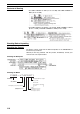
Wiring Selecting Frequency Reference Input Method Chapter 2-2 By using SW7, NPN or PNP input can be selected as shown below. 24V NPN SW7 GND S1 to S1 to 55 3.3k 0.1µ 360 SC GND 24V PNP SW7 GND S1 to55 S1 to 3.3k 0.1µ 24VVDC 24 DC (+10%) (+10%) 360 SC GND Selecting Frequency Reference Input Method By using SW8, frequency reference voltage or current input can be selected. Parameter settings are required together with the selection of the frequency reference input method.
Wiring 2-2-3 Chapter 2-2 Standard Connections DC reactor (optional) Noise Filter 3-phase 200 V AC Single-phase 200 V AC (see note 1) 3-phase 400 V AC Multi-function contact output Forward/Stop NO Multi-function input 1 (S2) NC Multi-function input 2 (S3) Common Multi-function input 3 (S4) Multi-function input 4 (S5) Sequence input common Frequency reference power supply 20 mA at +12 V FREQ adjuster Analog monitor output Analog monitor output common Frequency reference input Frequency reference
Wiring 2-2-4 Chapter 2-2 Wiring around the Main Circuit Wire Size, Terminal Screw, Screw Tightening Torque, and Molded-case Circuit Breaker Capacities For the main circuit and ground, always use 600-V polyvinyl chloride (PVC) cables. If any cable is long and may cause voltage drops, increase the wire size according to the cable length.
Wiring Chapter 2-2 Single-phase 200-V AC Model Model CIMR-J7AZ- Terminal symbol Terminal screw Terminal torque (N•m) Wire size (mm2) B0P1 R/L1, S/L2, T/L3, –, +1, +2, U/T1, V/T2, W/T3 M3.5 0.8 to 1.0 0.75 to 2 ReCircuit commended breaker wire size capacity (A) (mm2) 2 5 B0P2 R/L1, S/L2, T/L3, –, +1, +2, U/T1, V/T2, W/T3 M3.5 0.8 to 1.0 0.75 to 2 2 5 B0P4 R/L1, S/L2, T/L3, –, +1, +2, U/T1, V/T2, W/T3 M3.5 0.8 to 1.0 0.
Wiring Chapter 2-2 Wiring on the Input Side of the Main Circuit Installing a Molded-case Circuit Breaker Always connect the power input terminals (R/L1, S/L2, and T/L3) and power supply via a molded case circuit breaker (MCCB) suitable to the Inverter. • Install one MCCB for every Inverter used. • Choose an appropriate MCCB capacity according to the Circuit breaker capacity column in the table on the previous page.
Wiring Chapter 2-2 Connecting Input Power Supply to the Terminal Block Input power supply can be connected to any terminal on the terminal block because the phase sequence of input power supply is irrelevant to the phase sequence (R/L1, S/L2, and R/L3).
Wiring Chapter 2-2 Wiring on the Output Side of the Main Circuit Connecting the Terminal Block to the Load Connect output terminals U/T1, V/T2, and W/T3 to motor lead wires U, V, and W. Check that the motor rotates forward with the forward command. Switch over any two of the output terminals to each other and reconnect if the motor rotates in reverse with the forward command. Never Connect a Power Supply to Output Terminals Never connect a power supply to output terminals U/T1, V/T2, or W/T3.
Wiring Chapter 2-2 Countermeasures against Induction Noise As described previously, a Noise Filter can be used to prevent induction noise from being generated on the output side. Alternatively, cables can be routed through a grounded metal pipe to prevent induction noise. Keeping the metal pipe at least 30 cm away from the signal line considerably reduces induction noise. Power supply MCCB CIMR-J7AZ Metal pipe VARISPEED 30 cm min.
Wiring Chapter 2-2 Ground Wiring • Always use the ground terminal with the following ground resistance: 200-V Inverter: 100 W or less 400-V Inverter: separate ground,10 W or less • Do not share the ground wire with other devices such as welding machines or power tools. • Always use a ground wire that complies with technical standards on electrical equipment and minimize the length of the ground wire. Leakage current flows through the Inverter.
Wiring Chapter 2-2 Harmonics ■ Definiton Harmonics consist of electric power produced from AC power and alternating at frequencies that are integral multiples of the frequency of the AC power. The following frequencies are harmonics of a 60- or 50-Hz commercial power supply.
Wiring Causes of Harmonics Generation Chapter 2-2 Usually, electric machines have built-in circuitry that converts commercial AC power supply into DC power. Such AC power, however, contains harmonics due to the difference in current flow between DC and AC. Obtaining DC from AC Using Rectifiers and Capacitors DC voltage is obtained by converting AC voltage into a pulsating one-side voltage with rectifiers and smoothing the pulsating one-side voltage with capacitors.
Wiring Chapter 2-2 Countermeasures with Reactors against Harmonics Generation DC/AC Reactors The DC reactor and AC reactor suppress harmonics and currents that change suddenly and greatly. The DC reactor suppresses harmonics better than the AC reactor. The DC reactor used with the AC reactor suppresses harmonics more effectively. The input power factor of the Inverter is improved by suppressing the harmonics of the input current of the Inverter.
Wiring 2-2-5 Chapter 2-2 Wiring Control Circuit Terminals A control signal line must be 50 m maximum and separated from power lines. The frequency reference must be input into the Inverter through shielded, twisted-pair wires. Wiring of Control I/O Terminals Wire each control I/O terminal under the following conditions. Wires and Tightening Torque Multi-function Contact Output (MA, MB, and MC) Terminal Tightening Wire Wire size screw size torque N•m M3 0.5 to 0.6 Single wire 0.5 to 1.
Wiring Chapter 2-2 Wiring Method 1. Loosen the terminal screws with a thin-slotted screwdriver. 2. Insert the wires from underneath the terminal block. 3. Tighten each terminal screw firmly to a torque specified in the previous tables. Note 1. Always separate the control signal line from the main circuit cables and other power cables. 2. Do not solder the wires to the control circuit terminals. The wires may not contact well with the control circuit terminals if the wires are soldered. 3.
Wiring 2-2-6 Chapter 2-2 Conforming to EC Directive The following description provides the wiring method of the Inverter to meet DC Directive requirements. If the following requirements are not satisfied, the whole equipment incorporating the Inverter will need further confirmation.
Wiring Chapter 2-2 Wiring the Power Supply Make sure that the Inverter and Noise Filter are grounded together. • Always connect the power input terminals (R/L1, S/L2, and T/L3) and power supply via a dedicated Noise Filter. • Reduce the length of the ground wire as much as possible. • Locate the Noise Filter as close as possible to the Inverter. Make sure that the cable length between the Noise Filter and the Inverter does not exceed 40 cm. • The following Noise Filters are available.
Wiring Grounding the Shield Chapter 2-2 In order to ground the shield securely, it is recommended that a cable clamp be directly connected to the ground plate as shown below. Ground plate Cable clamp Cable Shield LVD Conformance • Always connect the Inverter and power supply via a molded case circuit breaker (MCCB) suitable to the Inverter for protecting the Inverter from damage that may result from short-circuiting. • Use one MCCB per Inverter. • Select a suitable MCCB from the following table.
Wiring Chapter 2-2 400-V Models Inverter Model CIMR-J7AZ40P2 40P4 40P7 41P5 42P2 44P0 NF30 MCCB (Mitsubishi Electric) Type Rated current (A) 5 5 5 10 10 20 To satisfy LVD (Low-voltage Directive) requirements, the system must be protected by a molded case circuit breaker (MCCB) when a short-circuit occurs. A single MCCB may be shared with more than one Inverter or with other machines.
CHAPTER 3 Preparing for Operation and Monitoring 3-1 Nomenclature. . . . . . . . . . . . . . . . . . . . . . . . . . . . . . . . . . . . . . . . . . . . . . . . . . 34 3-2 Outline of Operation . . . . . . . . . . . . . . . . . . . . . . . . . . . . . . . . . . . . . . . . . . . .
Nomenclature 3-1 Chapter 3-1 Nomenclature Indicators Setting/Monitor item indicators Data display FREQ adjuster Keys Appearance Name Data display Function Displays relevant data items, such as frequency reference, output frequency, and parameter set values. FREQ adjuster Sets the frequency reference within a range between 0 Hz and the maximum frequency. FREF indicator The frequency reference can be monitored or set while this indicator is lit.
Outline of Operation 3-2 Chapter 3-2 Outline of Operation Selecting Indicators Whenever the Mode Key is pressed, an indicator is lit in sequence beginning with the FREF indicator. The data display indicates the item corresponding to the indicator selected. The FOUT or IOUT indicator will be lit by turning the Inverter on again if the Inverter is turned off while the FOUT or IOUT indicator is lit.
Outline of Operation Chapter 3-2 Example of Frequency Reference Settings Key sequence Indicator Display example Explanation Power ON Note If the FREF indicator has not been lit, press the Mode Key repeatedly unit the FREF indicator is lit. Use the Increment or Decrement Key to set the frequency reference. The data display will flash while the frequency reference is set. (see note 1) Press the Enter Key so that the set value will be entered and the data display will be lit. (see note 1) Note 1.
Outline of Operation Chapter 3-2 Status Monitor Item U01 U02 U03 U04 Display Frequency reference Output frequency Output current Output voltage Display unit Hz Hz A V U05 DC bus voltage V U06 Input terminal status --- Function Monitors the frequency reference. (Same as FREF) Monitors the output frequency. (Same as FOUT) Monitors the output current. (Same as IOUT) Monitors the internal output voltage reference value of the Inverter.
Outline of Operation Chapter 3-2 Example of Forward/Reverse Selection Settings Key sequence Indicator Display example Explanation Press the Mode Key repeatedly until the F/R indicator is lit. The present setting will be displayed. For: Forward; rEv: Reverse Use the Increment or Decrement Key to change the direction of motor rotation. The direction of motor rotation selected will be enabled when the display changes after the key is pressed.
Outline of Operation Chapter 3-2 Example of Paramter Settings Cancels set data. In approximately 1 s. Key sequence Indicator Display example Explanation Power ON Press the Mode Key repeatedly until the PRGM indicator is lit. Use the Increment or Decrement Key to set the parameter number. Press the Enter Key. The data of the selected parameter number will be displayed. Use the Increment or Decrement Key to set the data. At that time the display will flash.
Outline of Operation 40 Chapter 3-2
CHAPTER 4 Test Run 4-1 4-2 Procedure for Test Run . . . . . . . . . . . . . . . . . . . . . . . . . . . . . . . . . . . . . . . . . . 43 Operation Example . . . . . . . . . . . . . . . . . . . . . . . . . . . . . . . . . . . . . . . . . . . . . 45 4-2-1 Power Connection . . . . . . . . . . . . . . . . . . . . . . . . . . . . . . . . . . . . . . . 45 4-2-2 Check the Display Status. . . . . . . . . . . . . . . . . . . . . . . . . . . . . . . . . . 45 4-2-3 Initializing Parameters. . . . . . . . .
Chapter 4 ! WARNING Turn ON the input power supply only after mounting the front cover, terminal covers, bottom cover, Operator, and optional items. Not doing so may result in electrical shock. ! WARNING Do not remove the front cover, terminal covers, bottom cover, Operator, or optional items while the power is being supplied. Not doing so may result in electrical shock or damage to the product. ! WARNING Do not operate the Operator or switches with wet hands. Doing so may result in electrical shock.
Procedure for Test Run 4-1 Chapter 4-1 Procedure for Test Run 1. Installation and Mounting Install the Inverter according to the installation conditions. Refer to page 6. Ensure that the installation conditions are met. 2. Wiring and Connection Connect to the power supply and peripheral devices. Refer to page 10. Select peripheral devices which meet the specifications and wire correctly. 3. Power Connection Carry out the following pre-connection checks before turning on the power supply.
Procedure for Test Run Chapter 4-1 9. Operation Basic Operation: Operation based on the basic settings required to start and stop the Inverter. Refer to page 5-1. Advanced Operation: Operation that uses PID control or other functions. Refer to page 6-1. • For operation within standard parameters, refer to Chapter 5 Basic Operation.
Operation Example 4-2 4-2-1 Chapter 4-2 Operation Example Power Connection Checkpoints before Connecting the Power Supply • Check that the power supply is on the correct voltage and that the motor output terminals (R/L1, S/L2, and T/L3) are connected to the motor correctly.
Operation Example 4-2-3 Chapter 4-2 Initializing Parameters • Initialize the parameters using the following procedure. • To initialize the parameters, set n01 to 8. Key sequence Indicator Display example Explanation Power ON Press the Mode Key repeatedly until the PRGM indicator is lit. v Press the Enter Key. The data of n01 will be displayed. Use the Increment or Decrement Key to set n01 to 8. The display will flash.
Operation Example 4-2-5 Chapter 4-2 No-load Operation • Start the no-load motor (i.e., not connected to the mechanical system) using the Digital Operator. Note Before operating the Digital Operator, check that the FREQ adjuster is set to MIN. Forward/Reverse Rotation with the Digital Operator Key sequence Indicator Display example Explanation Press the Mode Key to turn on the FREF indicator. Monitors the frequency reference. Press the RUN Key. The RUN Indicator will be lit.
Operation Example 4-2-6 Chapter 4-2 Actual Load Operation • After checking the operation with the motor in no-load status, connect the mechanical system and operate with an actual load. Note Before operating the Digital Operator, check that the FREQ adjuster is set to MIN. Connecting the System • After confirming that the motor has stopped completely, connect the mechanical system. • Be sure to tighten all the screws when fixing the motor axis in the mechanical system.
CHAPTER 5 Basic Operation 5-1 Initial Settings . . . . . . . . . . . . . . . . . . . . . . . . . . . . . . . . . . . . . . . . . . . . . . . . . 50 5-2 V/f Control. . . . . . . . . . . . . . . . . . . . . . . . . . . . . . . . . . . . . . . . . . . . . . . . . . . . 51 5-3 Setting the Local/Remote Mode . . . . . . . . . . . . . . . . . . . . . . . . . . . . . . . . . . . 53 5-4 Selecting the Operation Command . . . . . . . . . . . . . . . . . . . . . . . . . . . . . . . . .
Initial Settings Chapter 5-1 This section explains the basic settings required to operate and stop the Inverter. The settings of parameters described here will be sufficient for simple Inverter operations. First, make these basic settings, then skip to the explanations of those special functions, even when your application requires special functions, such as stall prevention, carrier frequency setting, overtorque detection, torque compensation, slip compensation. Refer to Chapter 6 Advanced Operation.
V/f Control 5-2 Chapter 5-2 V/f Control Setting the V/f Patterns (n09 to n15) • Set the V/f pattern so that the motor output torque is adjusted to the required load torque. • The J7AZ incorporates an automatic torque boost function. Therefore, a maximum of 150% torque can be output at 3 Hz without changing the default settings. Check the system in trial operation and leave the default settings as they are if no torque characteristic changes are required. n09 Setting range Maximum Frequency (FMAX) 50.
V/f Control Chapter 5-2 2. With 400-V Inverters, the values for the upper limit of setting ranges and the default settings will be twice those given in the above table. Output voltage (V) Note 1. Set the parameters so that the following condition will be satisfied. n14 ≤ n12 < n11 ≤ n09 Note 2. The value set in n13 will be ignored if parameters n14 and n12 are the same in value.
Setting the Local/Remote Mode 5-3 Chapter 5-3 Setting the Local/Remote Mode The J7AZ operates in local or remote mode. The following description provides information on these modes and how to select them. Basic Conecpt Operation mode Remote Basic concept The Inverter in a system operates according to the control signal of the host controller. Local The Inverter in a system operates independently in this mode so that the Inverter can be checked independently.
Selecting the Operation Command 5-4 Chapter 5-4 Selecting the Operation Command The following description provides information on how to input operation commands to start or stop the Inverter or change the direction of rotation of the Inverter. Three types of command input methods are available. Select either one of them according to the application. Selecting the Operation Mode (n02) • Select the method of operation mode input to start or stop the Inverter.
Setting the Frequency Reference 5-5 Chapter 5-5 Setting the Frequency Reference 5-5-1 Selecting the Frequency Reference The following description provides information on how to set the frequency reference in the Inverter. Select the method according to the operation mode. Remote mode: Select and set one out of six frequency references in n03. Local mode: Select and set one out of two frequency references in n07.
Setting the Frequency Reference 5-5-2 Chapter 5-5 Upper and Lower Frequency Reference Limits Regardless of the methods of operation mode and frequency reference input, the upper and lower frequency reference limits can be set. Setting the Frequency Reference Upper and Lower Limits (n30 and n31) • Set the upper and lower frequency reference limits as percentage based on the maximum frequency as 100%. n30 Setting range Frequency Reference Upper Limit 0% to 110% (Max.
Setting the Frequency Reference 5-5-4 Chapter 5-5 Setting Frequency References through Key Sequences The following description provides information on parameters related to frequency reference settings through key sequences on the Digital Operator Setting Frequency References 1 through 8 and the Inching Frequency Command (n21 through n28 and n29) A total of nine frequency references (frequency references 1 through 8) and an inching frequency command can be set together in the Inverter.
Setting the Frequency Reference Frequency reference Chapter 5-5 Frequency reference 1 Frequency reference 2 Frequency reference 3 Frequency reference 4 Frequency reference 5 Frequency reference 6 Frequency reference 7 Frequency reference 8 OFF ON OFF ON OFF ON OFF ON Multi-step speed reference 3 (Set value: 8) Multi-step speed reference 2 (Set value: 7) Multi-step speed reference 1 (Set value: 6) OFF OFF ON ON OFF OFF ON ON OFF OFF OFF OFF ON ON ON ON No multi-step speed reference 3 settings will be
Setting the Frequency Reference Chapter 5-5 Setting the Frequency Reference with the FREF Indicator Lit The frequency reference can be set while the FREF indicator of the Digital Operator is lit in the following cases. • Parameter n03 for frequency reference selection is set to 1, which enables frequency reference 1, and the Inverter is in remote mode. • Parameter n07 for frequency selection in local mode is set to 1, which enables key sequences on the Digital Operator, and the Inverter is in local mode.
Setting the Acceleration/Deceleration Time 5-6 Chapter 5-6 Setting the Acceleration/Deceleration Time The following description provides information on parameters related to acceleration and deceleration time settings. Trapezoidal and S-shape acceleration and deceleration are available. Using the Sshape characteristic function for acceleration and deceleration can reduce shock to the machinery when stopping or starting.
Setting the Acceleration/Deceleration Time Chapter 5-6 S-shape Acceleration/Deceleration Characteristic (n20) • Trapezoidal and S-shape acceleration and deceleration are available. Using the S-shape characteristic function for acceleration and deceleration can reduce shock to the machinery when stopping or starting. • Any one of three S-shape acceleration/deceleration times (0.2, 0.5, and 1.0 s) is selectable.
Selecting the Reverse Rotation-prohibit 5-7 Chapter 5-7 Selecting the Reverse Rotation-prohibit This parameter is used to specify whether to enable or disable the reverse rotation command sent to the Inverter from the control circuit terminals or Digital Operator. The parameter should be set to “not accept” when the Inverter is applied to systems that prohibit the reverse rotation of the Inverter.
Multi-function I/0 5-9 5-9-1 Chapter 5-9 Multi-function I/0 Multi-function Input The J7AZ incorporates four multi-function input terminals (S2 through S5). Inputs into these terminals have a variety of functions according to the application.
Multi-function I/0 Chapter 5-9 Set Values Value 0 2 3 4 5 6 7 8 10 11 12 13 14 15 16 17 18 Function Forward/Reverse rotation command Description 3-wire sequence (to be set in n37 only) By setting n37 to 0, the set value in n36 is ignored and the following setting are forcibly made.
Multi-function I/0 Chapter 5-9 Operation in 2-wire Sequence (Set Value: 2) • The Inverter operates in 2-wire sequence by setting a multi-function input parameter to 2 (reverse/stop). • The following diagram shows a wiring example of the terminals in 2-wire sequence.
Multi-function I/0 Chapter 5-9 Speed Search (Set Value: 14, 15) The speed search function is provided for smooth restarting without stopping a free running motor. Use it when switching the motor from commercial power supply operation to Inverter operation, when starting with the Inverter a motor turned by external force, etc. The speed search function searches for the present motor frequency, from high frequency to low.
Multi-function I/0 5-9-2 Chapter 5-9 Multi-function Output The J7AZ incorporates two multi-function output terminals (MA and MB). Output from these terminals has a variety of functions according to the application. Selecting the Multi-function Output (n40) n40 Multi-function Output (MA/MB and MC) Setting range 0 to 7, 10 to 17 (see note) Note Unit of setting 1 Changes during operation Default setting No 1 Do not set values outside the above setting ranges.
Analog Monitor Output Chapter 5-10 5-10 Analog Monitor Output The J7AZ incorporates analog monitor output terminals AM and AC. These terminals have analog monitor values of output frequency or current. Setting the Analog Monitor Output (n44 and n45) • The output frequency or current as a monitored item is set in n44. • The analog output characteristics are set as an analog monitor output gain in n45.
CHAPTER 6 Advanced Operation 6-1 Setting the Carrier Frequency . . . . . . . . . . . . . . . . . . . . . . . . . . . . . . . . . . . . . 70 6-2 DC Injection Braking Function . . . . . . . . . . . . . . . . . . . . . . . . . . . . . . . . . . . . 72 6-3 Stall Prevention Function . . . . . . . . . . . . . . . . . . . . . . . . . . . . . . . . . . . . . . . . 73 6-4 Overtorque Detection Function . . . . . . . . . . . . . . . . . . . . . . . . . . . . . . . . . . . .
Setting the Carrier Frequency Chapter 6-1 This chapter provides information on the use of advanced functions of the Inverter for operation. Refer to this chapter to use the various advanced functions, such as stall prevention, carrier frequency setting, overtorque detection, torque compensation, and slip compensation. 6-1 Setting the Carrier Frequency The carrier frequency of the J7AZ can be fixed or varied in proportion to the output frequency.
Setting the Carrier Frequency Chapter 6-1 The Inverter cannot maintain rated output current with the carrier frequency set to a value higher than the default one. The following table shows the default value and a decrease in the output current of each Inverter model. Be sure to use the Inverter so that there will be no decrease in rated output current.
DC Injection Braking Function 6-2 Chapter 6-2 DC Injection Braking Function The DC injection braking function applies DC on the induction motor for braking control. Startup DC Injection Braking: This braking is used for stopping and starting the motor rotating by inertia with no regenerative processing. DC Injection Braking to Stop: Adjust the stop DC injection braking time if the motor rotating does not decelerate to a stop in normal operation due to inertia from a heavy load.
Stall Prevention Function 6-3 Chapter 6-3 Stall Prevention Function A stall will occur if the motor cannot keep up with the rotating magnetic field on the motor stator side when a large load is applied to the motor or a sudden acceleration/deceleration is performed. In the J7AZ, stall prevention functions can be set independently for accelerating, running, and decelerating conditions.
Stall Prevention Function n56 Chapter 6-3 Stall Prevention Level during Acceleration Setting range 30 to 200 (%) Set Values Unit of setting 1% Changes during operation Set Values No 170 • This function is used to stop accelerating the load if the output current exceeds the set current value so that the Inverter will continue operating without stalling. The Inverter accelerates the load while the output current is the same as or less than the set value.
Stall Prevention Function n57 Chapter 6-3 Stall Prevention during Operation Setting range 30 to 200 (%) Set Values Unit of setting Changes during operation 1% Default setting No 160 • This function will decrease the output frequency if the output current exceeds the set current value by a minimum of approximately 100 ms so that the Inverter will continue operating without stalling.
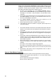
Overtorque Detection Function 6-4 Chapter 6-4 Overtorque Detection Function When an excessive load is applied to the equipment, the Inverter detects the overtorque condition through an increase in the output current. n59 Setting range Overtorque Detection Function Selection 0 to 4 Unit of setting 1 Changes during operation Default setting No 0 Set Values Value 0 1 Description Inverter does not monitor overtorque. Inverter monitors overtorque only when speed is matched.
Torque Compensation Function Set Values Chapter 6-5 Set the parameter as percentage based on the rated Inverter current as 100%. n61 Overtorque Detection Time Setting range 0.1 to 10.0 (s) Set Values Unit of setting Changes during operation 0.1 s Default setting No 0.1 • Set the overtorque detection time. • The Inverter will detect overtorque when the current the same as or higher than the detection level is output for the preset detection time.
Slip Compensation Function 6-6 Chapter 6-6 Slip Compensation Function The slip compensation function calculates the motor torque according to the output current, and sets gain to compensate for output frequency. This function is used to improve speed accuracy when operating with a load. n64 Setting range Motor Rated Slip 0.0 to 20.0 (Hz) Note Set Values Unit of setting Changes during operation 0.
Other Functions 6-7 Chapter 6-7 Other Functions The following description provides information on the other functions and parameter settings of the Inverter. 6-7-1 Motor Protection Characteristics (n33 and n34) This parameter setting is for motor overload detection (OL1).
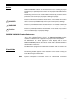
Other Functions 6-7-2 Chapter 6-7 Cooling Fan Operation Function (n35) This parameter is used to operate the cooling fan of the Inverter while the Inverter is turned on or only while the Inverter is in operation. n35 Setting range Cooling Fan Operation Selection 0, 1 Unit of setting Changes during operation 1 Default setting No 0 Set Values Value 0 1 Description The fan rotates only while the RUN command is input and for 1 minute after the Inverter stops operating.
Other Functions 6-7-4 Chapter 6-7 Fault Retry (n48) ! Caution The Inverter may be break if the fault retry function is used. If the Inverter breaks, take the following measures: Be sure to install a no-fuse breaker (NFB). Provide the Inverter and peripheral machines with a sequence so that the machines will stop operating when the Inverter has an operational fault.
Other Functions 6-7-5 Chapter 6-7 Frequency Jump Function (n49 to n51) • The frequency jump function prevents the Inverter from generating frequencies that make the mechanical system resonate. • The frequency jump function can be used effectively to set two dead bands of a frequency reference. n49 Setting range Jump Frequency 1 0.0 to 400 (Hz) n50 Setting range 0.1 Hz (see note) Jump Frequency 2 0.0 to 400 (Hz) n51 Setting range Unit of setting Changes during operation Unit of setting 0.
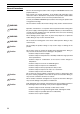
Other Functions 6-7-6 Chapter 6-7 Frequency Detection Function • The 3G3JV has the following frequency detection functions. Frequency Detection: Detects that the frequency reference coincides with the output frequency. Frequency Detection Levels 1 and 2: Detects that the output frequency is the same as or higher or lower than the set value (frequency detection level) in n58. • The parameter n40 for multi-function output must be set for the frequency detection function.
Other Functions Chapter 6-7 Frequency Detection Levels 1 and 2 • The parameter n40 for multi-function output must be set for frequency detection output. Set value: 4 for frequency detection level 1 (Output frequency ≥ n58) Set value: 5 for frequency detection level 2 (Output frequency ≤ n58) • Set the frequency detection level in n58. n58 Setting range Frequency Detection Level 0.0 to 400 (Hz) Note Unit of setting 0.1 Hz (see note) Changes during operation Default setting No 0.
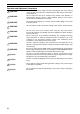
Other Functions 6-7-7 Chapter 6-7 UP/DOWN Command Frequency Memory (n62) • This function changes the reference frequency by turning the UP and DOWN commands on and off. • In order to use this function, set n39 for multi-function inputs 4 to 34. Then the multi-function input 3 (S4) and multi-function input 4 (S5) terminals are set as described below. Multi-function input 3 (S4): UP command (The value in n38 for multifunction input 3 is ignored.
Other Functions Chapter 6-7 Set Values Value Description 0 1 The frequency on hold is not retrained. The frequency on hold for 5 s or more is retailed. Operation of UP/DOWN Function RUN command (Forward rotation) Time UP command (S4) Time DOWN command (S5) Time Output frequency Upper limit Lower limit Time Status Frequency detection Note Time Status U: UP (acceleration) D: DOWN (deceleration) H: Hold U1: Frequency acceleration restricted by upper limit.
Other Functions Chapter 6-7 • When the RUN command for forward or reverse rotation is input, the Inverter will start operating at the lower limit regardless of whether the UP/ DOWN command is input or not. • When the UP/DOWN function and inching frequency command are both assigned to multi-function inputs, an inching frequency command input will have the highest priority.
Other Functions 88 Chapter 6-7
CHAPTER 7 Communications 7-1 7-2 RS-422/485 Communications Unit . . . . . . . . . . . . . . . . . . . . . . . . . . . . . . . . . 90 7-1-1 Overview . . . . . . . . . . . . . . . . . . . . . . . . . . . . . . . . . . . . . . . . . . . . . . 90 7-1-2 External Dimensions . . . . . . . . . . . . . . . . . . . . . . . . . . . . . . . . . . . . . 90 7-1-3 Names of Parts . . . . . . . . . . . . . . . . . . . . . . . . . . . . . . . . . . . . . . . . . 91 7-1-4 Mouting Procedure . . . . . . . . . . .
RS-422/485 Communications Unit Chapter 7-1 Using a SI-485/J7 (3G3JV-PSI485J) RS-422/485 Communications Unit allows J7AZ Inverters to participate in RS-422/485 serial communications. This makes Inverter control input, frequency reference input, monitoring of the Inverter’s operating status, and reading and writing of parameter settings all possible via communications. Up to 32 Inverters can be connected to the Unit to enable easy creation of networks. Note 1.
RS-422/485 Communications Unit 7-1-3 Chapter 7-1 Names of Parts Terminal block Terminating resistance switch Terminal Block 1 S– 2 3 S+ Shield 4 5 R– R+ Terminating Resistance Switch SW OFF ON Note 7-1-4 Set the terminating resistance switch to ON to connect the terminating resistance. Mouting Procedure Use the following procedure to mount an RS-422/485 Communications Unit SI-485/J7 (3G3JV-PSI485J) to a J7AZ Inverter. 1. Turn OFF the Inverter’s power supply.
RS-422/485 Communications Unit Chapter 7-1 4. Align the Unit with the Inverter’s connector, and push the Unit onto the Inverter (so that the 3 catches enter the corresponding holes) until it is securely mounted. Connector 5. Mount the front cover (removed previously) on top of the RS-422/485 Communications Unit, and secure it using the front cover mounting screws. (Do not mount the optional cover.) Note 92 When not using the RS-422/485 Communications Unit, be sure to mount the optional cover.
Inverter Settings 7-2 Chapter 7-2 Inverter Settings 7-2-1 Setting the Communications Conditions Communications Time-over Detection Selection (n68) • This parameter is used for monitoring the communications system. • The set value in the parameter determines whether communications timeover detection will be performed with “CE” displayed if there is an interval of more than 2 s between normal communications.
Inverter Settings Chapter 7-2 Set Values Value 0 1 2 3 Description 0.1 Hz 0.01 Hz Converted value based on 30,000 as max. frequency 0.1% (Max. frequency: 100%) Note Communications data after the above conversion is hexadecimal. For example, if the frequency is 60 Hz and the unit of setting is 0.01 Hz, the converted value is obtained as follows: 60/0.01 = 6000 = 1770 Hex Slave Address (n70) • Set this parameter to the Slave address (Slave unit number) for communications.
Inverter Settings Chapter 7-2 n72 RS-422A/485 Parity Selection Register 0148 Hex Changes during operation No Setting range 0 to 2 Unit of setting 1 Default setting 2 Set Values Value 0 1 2 Description Even Odd No parity In normal serial communications, data is configured in single bytes, and messages are created by stringing together multiple bytes of data. The parity check described here sets the check for each byte of data. Set the parity check method that is required by the Master.
Inverter Settings 7-2-2 Chapter 7-2 Operation Command Selection (n02) • Select the method to input the RUN or STOP command into the Inverter. • This parameter is enabled in remote mode only. The Inverter in local mode accepts the RUN command only through key sequences on the Digital Operator.
Inverter Settings 7-2-4 Chapter 7-2 Setting the Multi-function Inputs (n36 to n39) • In addition to the methods described above, the RUN command and frequency reference can be input through RS-422A/485 communications by setting the value 18 in any one of the parameters from n36 to n39 (multi-function input). • Subsequently, the following operations are selectable in remote mode. None of these parameters, however, can be changed while the operation command is being input.
Message Communications Basic Format 7-3 Chapter 7-3 Message Communications Basic Format The following description provides information on the format of message data (DSR and response data). Message communications of the Inverter conform to the MODBUS Communications Protocol, which does not require message start and end processing. (The MODBUS Communications Protocol is a trademark of AEG Schneider Automation.) Communications Format • The following format is used for message data communications.
Message Communications Basic Format Chapter 7-3 Slave Address • The Master can communicate with a maximum of 32 Slaves over RS422A/485. A unique Slave address is allocated to each Slave (Inverter) for communications. • Slave addresses are within a range from 00 to 32 (00 through 20 Hex). If a DSR message is issued to Slave address 00, the message will be a broadcast message. Note The broadcast message is addressed to all Slaves.
Message Communications Basic Format Chapter 7-3 Error Check The CRC-16 check code is the remainder (16 bits) when all of the message blocks from the Slave address to the final communications data are connected in series, as shown in the following diagram, and this data is divided by a fixed 17-digit binary number (1 1000 0000 0000 0101). 8 bits The LSB of the Slave address is handled as the MSB in CRC-16 calculation.
DSR Message and Response 7-4 Chapter 7-4 DSR Message and Response The following description provides information on how to set DSR messages and what details are returned as responses. Each DSR message or response is divided into 8-bit blocks. Therefore, data must be set in 8-bit blocks for communications.
DSR Message and Response Chapter 7-4 Response Normal Byte No. 1 2 3 4 5 6 7 8 9 : n–1 n Data Slave address Function code (03 Hex) Number of bytes of attached data Data of start register MS B LSB MSB LSB MSB LSB : Data of next register Data of next register : CRC-16 check Error Byte No. 1 2 3 4 5 Data Slave address Function code (83 Hex) Error code CRC-16 check Note When an error occurs, the MSB of the function code will be set to 1.
DSR Message and Response Chapter 7-4 Response Normal Byte No. 1 2 3 4 5 6 7 8 9 10 11 12 13 Data Slave address Function code Number of bytes of attached data Data in register No. 0020 MS B LSB MSB LSB MSB LSB MSB LSB Data in register No. 0021 Data in register No. 0022 Data in register No. 0023 CRC-16 check Data example (Hex) 02 03 08 00 65 00 00 00 00 01 F4 AF 82 Error Byte No.
DSR Message and Response Chapter 7-4 DSR Message Byte No. 1 2 3 4 5 6 7 8 9 10 11 12 13 : n–1 n Data Slave address Function code (10 Hex) Register No. of write start data Number of registers of write data (max. 16) Data of start register Data of next register MSB LSB MSB LSB MSB LSB : Data of next register Data of next register : CRC-16 check Response Normal Byte No. 1 2 3 4 5 6 7 8 Data Slave address Function code (10 Hex) Register No.
DSR Message and Response Chapter 7-4 Example of Data Read In the following example, two-register data (the RUN command) is written from register 0002 Hex of the Inverter with a Slave address of 01. DSR Message Byte No. 1 2 3 4 5 6 7 8 9 10 11 12 13 Data Slave address Function code Register No. of write start data Number of registers of write data Data of start register Data in register No. 0001 MSB LSB MSB LSB Data in register No.
DSR Message and Response 7-4-3 Chapter 7-4 Loop-back Test (Function Code: 08 Hex) Settings and Response • The DSR message from the Master is returned as a response. The Inverter does not retrieve or process this data. • The DSR message or normal response for loop-back test use is divided into 8-byte blocks as shown below. Any data can be set as test data 1 or 2 provided that the number of data items remains changed.
DSR Message and Response Chapter 7-4 Example of Loop-back Test In the following example, a loop-back test is conducted on the Inverter with a Slave address of 01. DSR Message Byte No. 1 2 3 4 5 6 7 8 Data Data example (Hex) 01 08 00 00 A5 37 DA 8D Data Data example (Hex) Slave address Function code Test data 1 Test data 2 CRC-16 check Response Normal Byte No. 1 2 3 4 5 6 7 8 Slave address Function code Test data 1 01 08 00 00 A5 37 DA 8D Test data 2 CRC-16 check Error Byte No.
Enter Command 7-5 Chapter 7-5 Enter Command The Enter command is used for copying parameter set values that have been written through communications in and after register 0101 Hex of the RAM area to the EEPROM of the Inverter. This is done so that the EEPROM can maintain the parameter set values. By issuing a DSR message to write data, the data is written to the RAM area of the Inverter. This data will be lost when the Inverter is turned OFF.
Setting the Communications Data 7-6 Chapter 7-6 Setting the Communications Data The following description provides information on how to convert the register data (such as monitor value or parameter set value data) in the communications data block of the message data (such as DSR and response data). Converting the Register Data • The data in each register is sent as 2-byte data. • The data in each register is processed under the following rules and sent in hexadecimal.
Setting the Communications Data Chapter 7-6 Negative Values Expressed in 2’s Complements If the frequency reference bias in n42 is –100%, the minimum unit of setting will be 1% and the data will be converted as follows: 100 (%)/1 (%) = 100 = 0064 Hex → 2’s complement: FF9C Hex Bit reversed. 1 is added. Note Whether the data is positive or negative is determined by the parameter set value. The MSB of negative-value data is always set to 1.
Register Number Allocations in Detail 7-7 Chapter 7-7 Register Number Allocations in Detail The following description provides information on register numbers allocated to the Inverter and the meanings of the registers. As for the register numbers of the parameters (n01 through n79), refer to Section 10 List of Parameters and the description of each of these parameters wherever explained in this manual.
Register Number Allocations in Detail Chapter 7-7 Broadcast Message with Slave Address: 00 (00 Hex) Write Register No. (Hex) Function 0000 Not used. 0001 RUN command 0002 Frequency reference 0003 to 000F Not used. Note Description --Refer to the table below. Set the frequency reference based on the maximum frequency as 30,000. --- 1. Data can be written to registers 0001 and 0002 only. Assumed previous values are held for unused registers. 2. No data can be written to multi-function input. 3.
Register Number Allocations in Detail Chapter 7-7 Status Signal (Register 0020 Hex) Bit No. 0 1 2 3 4 5 6 to 15 Function During RUN (1: During RUN) Forward/reverse operation (1: Reverse operation) Inverter ready (1: Ready) Fault (1: Fault) Data setting error (1: Error) Multi-function output (1: ON) Not used. Fault Status (Register 0021 Hex) Bit No. 0 1 2 3 4 5 6 7 Function OC OV OL2 OH Not used. Not used. Not used. EF_, STP Note Bit No. 8 9 10 11 12 13 14 15 Function F_ OL1 OL3 Not used.
Register Number Allocations in Detail Chapter 7-7 Inverter Status 1 (Register 002C Hex) Bit No.
Communications Error Codes 7-8 Chapter 7-8 Communications Error Codes The Inverter will detect a communications error if normal communications fail or a message data error occurs. The Inverter returns a response that consists of the Slave address, function code with the MSB set to 1, error code, and CRC-16 check block when the communications error is detected. When the Master receives an error code, refer to the following table for troubleshooting and remedying the error.
Self-diagnostic Test 7-9 Chapter 7-9 Self-diagnostic Test The Inverter incorporates a self-diagnostic test function that checks whether RS-422A/485 communications are functioning. If the Inverter has a communications failure, take the steps provided below to check whether the communications function of the Inverter is normal. Self-diagnostic Test Steps 1. Set the Parameter Set n39 for multi-function input 4 (S5) to 35 through the Digital Operator. 2.
CHAPTER 8 Communications 8-1 8-2 8-3 Protective and Diagnostic Functions . . . . . . . . . . . . . . . . . . . . . . . . . . . . . . . . 118 8-1-1 Fault Detection (Fatal Error) . . . . . . . . . . . . . . . . . . . . . . . . . . . . . . . 118 8-1-2 Warning Detection (Nonfatal Error) . . . . . . . . . . . . . . . . . . . . . . . . . 121 Troubleshooting . . . . . . . . . . . . . . . . . . . . . . . . . . . . . . . . . . . . . . . . . . . . . . . . 123 8-2-1 123 Parameters Fail Set . . . . . . .
Protective and Diagnostic Functions 8-1 Chapter 8-1 Protective and Diagnostic Functions 8-1-1 Fault Detection (Fatal Error) The Inverter will detect the following faults if the Inverter or motor burns or the internal circuitry of the Inverter malfunctions. When the Inverter detects a fault, the fault code will be displayed on the Digital Operator, the fault contact output will operate, and the Inverter output will be shut off causing the motor to coast to a stop.
Protective and Diagnostic Functions Fault display %h Fault name and meaning Radiation fin overheated (OH) The temperature of the radiation fins of the Inverter has reached 110°C ± 10°C. Chapter 8-1 Probable cause and remedy • The ambient temperature is too high. → Ventilate the Inverter or install a cooling unit. • The load is excessive. → Reduce the load. → Decrease the Inverter capacity. • The V/f setting is incorrect. → Reduce the V/f set voltage. • The acceleration/deceleration time is too short.
Protective and Diagnostic Functions Fault display f00 f01 f04 f05 f07 ce Fault name and meaning Chapter 8-1 Probable cause and remedy Digital Operator transmission • The internal circuitry of the Inverter has a fault. fault 1 (F00) → Turn the Inverter off and on. → Replace the Inverter if the same fault occurs again. An initial memory fault has been detected Digital Operator transmission • The internal circuitry of the Inverter has a fault. fault 2 (F01) → Turn the Inverter off and on.
Protective and Diagnostic Functions 8-1-2 Chapter 8-1 Warning Detection (Nonfatal Error) The warning detection is a type of Inverter protective function that does not operate the fault contact output and returns the Inverter to its original status once the cause of the error has been removed. The Digital Operator flashes and display the detail of the error. If a warning occurs, take appropriate countermeasures according to the table below.
Protective and Diagnostic Functions Fault display ef (flashing) stp (flashing) fRn (flashing) Warning name and Meaning Forward- and reverse-rotation input (EF) The forward and reverse commands are input to the control circuit terminals simultaneously for 0.5 s or more. Note The Inverter stops according to the method set in n04. Emergency stop (STP) The Digital Operator stops operating.
Troubleshooting 8-2 Chapter 8-2 Troubleshooting Due to parameter setting errors, faulty wiring, and so on, the Inverter and motor may not operate as expected when the system is started up. If that should occur, use this section as a reference and apply the appropriate measures. Refer to 8-1 Protective and Diagnostic Functions, if the contents of the fault are displayed. 8-2-1 Parameters Fail Set The display does not change when the Increment or Decrement Key is pressed.
Troubleshooting The wiring on the Inverter control circuit terminals is incorrect. Chapter 8-2 The Inverter cannot check input signals if the input wiring on the control circuit terminals is incorrect. Operate the Digital Operator and check the input terminal status of multifunction monitor U06. The NPN or PNP input sequence is selectable. The NPN input sequence is the default setting. Refer to 2-2-2 Terminal Block and check that the setting of switch SW7 and wiring are correct.
Troubleshooting 8-2-4 Chapter 8-2 Motor Outputs No Torque or Acceleration is Slow The stall prevention level during running is too low. If the value in n57 for stall prevention level during operation is too low, the speed will drop before torque output is turned ON. Check to be sure that the set value is suitable. The stall prevention level during acceleration is too low. 8-2-5 If the value in n56 for stall prevention level during acceleration is too slow, the acceleration time will be too long.
Troubleshooting 8-2-7 Chapter 8-2 Controller or AM Radio Receives Noise when Inverter is Started Noise derives from Inverter switching. Take the following actions to prevent noise. • Lower the carrier frequency of the Inverter in n46. The number of internal switching times is reduced, so noise can be reduced to some extent. • Install an Input Noise Filter. Install an Input Noise Filter on the power input area of the Inverter. • Install an Output Noise Filter.
Troubleshooting Chapter 8-2 8-2-10 Motor Rotates after Output of Inverter is Turned Off Insufficient DC Control If the motor continues operating at low speed, without completely stopping, and after a deceleration stop has been executed, it means that the DC braking is not decelerating enough. In such cases, adjust the DC control as described below. • Increase the parameter in n52 for DC control current. • Increase the parameter in n53 for interruption DC control time.
Maintenance and Inspection 8-3 Chapter 8-3 Maintenance and Inspection ! WARNING ! WARNING Do not touch the Inverter terminals while the power is being supplied. Maintenance or inspection must be performed only after turning OFF the power supply, confirming that the CHARGE indicator (or status indicators) is turned OFF, and after waiting for the time specified on the front cover. Not doing so may result in electrical shock.
Maintenance and Inspection Chapter 8-3 Periodic Maintenance Parts The Inverter is configured of many parts, and these parts must operate properly in order to make full use of the Inverter’s functions. Among the electronic components, there are some that require maintenance depending on their usage conditions. In order to keep the Inverter operating normally over a long period of time, it is necessary to perform periodic inspections and replace parts according to their service life.
Maintenance and Inspection Chapter 8-3 2. Hold the fan wire and pull the protective tube of the cover in the arrow 3 direction. Protective tube There is a connector inside. Fan wind direction 3. Slide the protective tube and remove the internal connector. 4. Remove the Fan from the fan cover. 5. Mount the new Fan on the fan cover. At this time, make sure that the wind direction of the Fan will be in the direction of the heat radiation fin. 6.
CHAPTER 9 Specifications 9-1 Inverter Specifications . . . . . . . . . . . . . . . . . . . . . . . . . . . . . . . . . . . . . . . . . . . 132 9-2 Specifications of Accessories . . . . . . . . . . . . . . . . . . . . . . . . . . . . . . . . . . . . . 135 9-2-1 List of Accessories . . . . . . . . . . . . . . . . . . . . . . . . . . . . . . . . . . . . . . 135 9-2-2 Adapter Panel . . . . . . . . . . . . . . . . . . . . . . . . . . . . . . . . . . . . . . . . . .
Inverter Specifications 9-1 3-phase 200-V AC models Singlephase 200-V AC models Inverter Specifications Model CIMR-J´7AZ Power Rated voltage supply and frequency Allowable voltage fluctuation Allowable frequency fluctuation Power supply capacity (kVA) (See note 1.
Inverter Specifications Control characteristics Chapter 9-1 Overload capacity External frequency set signal Acceleration/deceleration time Braking torque Protection function Voltage/frequency characteristics Motor protection Instantaneous overcurrent protection Overload protection Overvoltage protection Undervoltage protection 150% of rated output current for 1 min Selectable with FREQ adjuster: 0 to 10 V DC (20 kW), 4 to 20 mA (250 W), and 0 to 20 mA (250 W) 0.
Inverter Specifications Chapter 9-1 Max. applicable motor capacity (kW) Rated output capacity (kVA) Output specifiRated output current (A) cations Rated output voltage (V) Max.
Specifications of Accessories 9-2 9-2-1 Chapter 9-2 Specifications of Accessories List of Accessories Mounting Accessories Name Adapter Panel (for J7AZ Series) Model SI232J/J7 & SI232J/J7C RS-422/485 Communications Unit SI485/J7 Fan Unit FAN00106_ Description Interface required to connect a Digital Operator to a J7AZ Inverter. There are two types of Adapter Panels available: a fixed type (SI232J/J7) and a detach-able type (SI232J/J7C). Use the detachable type for copying parameters.
Specifications of Accessories 9-2-2 Chapter 9-2 Adapter Panel SI232/J7_ An Adapter Panel is required as an interface to connect a Digital Operator (JVOP-140 or JVOP-146) to the J7AZ Inverter. There are two models of Adapter Panel available. The SI232/J7 is permanently installed and cannot be removed and the SI232/J7C for copying parameters is installed so that it can be removed.
Specifications of Accessories 9-2-3 Chapter 9-2 RS-422/485 Communications Unit SI485/J7 The RS-422/485 Communications Unit (SI485/J7) functions as an interface for RS-422/485 general-purpose communications. The communications protocol conforms to MODBUS (same protocol as V7AZ and F7 Inverters). Communications can be used for Inverter control inputs, frequency references, monitoring Inverter operating status, and reading/writing parameter settings. Note Refer to CHAPTER 7 Communications for details.
Specifications of Accessories 9-2-5 Chapter 9-2 Digital Operator JVOP-140/JVOP-146 The Digital Operator (JVOP-140/JVOP-146) is used to control the Inverter from a distance. There are two models available. The JVOP-140 is equipped with an adjuster and the JVOP-146 is not. Always use the JVOP140 together with a Digital Operator Case (3G3IVPEZZ08386A). Without the Case, the Digital Operator’s connection cable cannot be wired. Using the Case also enables mounting to a control panel.
Specifications of Accessories 9-2-6 Chapter 9-2 Digital Operator Case 3G3IV-PEZZ08386A The Digital Operator Case (3G3IV-PEZZ08386A) is used to secure the JVOP140 Digital Operator. Without this Case, the Digital Operator’s connection cable cannot be wired. Always use the JVOP-140 and the Digital Operator Case together. Dimensions (mm) Four, 4.4-dia. mounting holes Four depressions for M4 bolts (Depth: 3.
Specifications of Accessories 9-2-9 Chapter 9-2 DIN Track Mounting Bracket 3G3IV-PEZZ08122_ An adapter making it possible to easily mount the Inverter to DIN tracks.
Specifications of Accessories Chapter 9-2 9-2-10 AC Reactor The AC Reactor suppresses harmonic current generated from the Inverter and improves the power factor of the Inverter. Connect the AC Reactor to the Inverter if the capacity of the power supply is much larger than that of the Inverter. Select the AC Reactor model from the following table according to the motor capacity.
Option Specifications 9-3 Chapter 9-3 Option Specifications 9-3-1 EMC-compatible Noise Filter • Be sure to select an optimum Noise Filter from the following so that the Inverter will satisfy EMC directive requirements of the EC Directives. • Connect the Noise Filter between the power supply and the input terminals (R/L1, S/L2, and T/L3) of the Inverter.
Option Specifications Chapter 9-3 External Dimensions Filters Schaffner model 3 x 200 V 3G3JV-PFI2010-SE 3G3JV-PFI2020-SE 1 x 200 V 3G3JV-PFI1010-SE 3G3JV-PFI1020-SE 3 x 400 V 3G3JV-PFI3005-SE 3G3JV-PFI3010-SE 3G3JV-PFI3020-SE A 194 169 169 169 169 169 174 B 82 111 71 111 111 111 144 C 50 50 45 50 50 50 50 D 160 135 135 135 135 135 135 E 181 156 156 156 156 61 61 Dimensions F G 62 5.3 91 5.5 51 5.3 91 5.3 91 5.
Option Specifications 144 Chapter 9-3
CHAPTER 10 List of Parameters List of Parameters . . . . . . . . . . . . . . . . . . . . . . . . . . . . . . . . . . . . . . . . . . . . . .
List of Parameters Chapter 10 List of Parameters ParaName meter No. (Register No.
List of Parameters Parameter No. (Register No. (Hex)) n07 (0107) n08 (0108) n09 (0109) Chapter 10 Name Description Setting Unit of Default Changes Referrange setting setting during ence operation page Frequency selection in local mode Used to set the input method for the frequency reference in local mode. 0: The FREQ adjuster of the Digital Operator enabled. 1: Key sequences on the Digital Operator enabled.
List of Parameters Parameter No. (Register No.
List of Parameters Parameter No. (Register No. (Hex)) n33 (0121) n34 (0122) n35 (0123) n36 (0124) n37 (0125) n38 (0126) Name Motor protection characteristics Chapter 10 Description Used to set the motor overload detection (OL1) for the electronic thermal characteristics of the motor.
List of Parameters Parameter No. (Register No.
List of Parameters Parameter No. (Register No. (Hex)) n39 (0127) Chapter 10 Name Multi-function input 4 (input terminal S5) Description 18 Communications or remote selection 19 Emergency stop fault (NO) 20 Emergency stop alarm (NO) 21 Emergency stop fault (NC) 22 Emergency stop alarm (NC) 34 Up or down command 35 Selfdiagnostic test ON: RS-422A/485 communications input is enabled. OFF: The settings of n02 and n03 are enabled.
List of Parameters Parameter No. (Register No. (Hex)) n40 (0128) Chapter 10 Name Description Multi-function Used to select the functions of multi-function 0 to 7, output terminals.
List of Parameters Parameter No. (Register No. (Hex)) n40 (0128) n41 (0129) n42 (012A) n43 (012B) Chapter 10 Name Description Setting Unit of Default Changes Referrange setting setting during ence operation page Multi-function 16 output (MA/MB and MC output 17 terminals) Rotating in ON: Rotating in reverse reverse direction direction ON: Speed search in Speed progress search in progress Frequency Used to the input characteristics of analog reference gain frequency references.
List of Parameters Parameter No. (Register No. (Hex)) Name n52 (0134) DC control current n53 (0135) Interruption DC control time n54 (0136) Chapter 10 Startup DC control time Description Used to impose DC on the induction motor 0 to 100 for braking control. Set the DC braking current in percentage based on the rated current of the Inverter as 0.0 to 100%. 25.5 n56 (0138) n57 (0139) n58 (013A) n59 (013B) 060 (013C) 061 (013D) 154 Stall prevention during deceleration 1% 50 No 6-5 0.
List of Parameters ParaName meter No. (Register No. (Hex)) 062 UP/DOWN (013E) command frequency memory n63 (013F) Torque compensation gain n64 (0140) Motor rated slip n65 (0141) Motor no-load current n66 (0142) Slip compensation gain n67 (0143) Slip compensation time constant n68 (0141) (See note 3.) RS-422A/485 communications timeover detection selection Chapter 10 Description Used to store the adjusted frequency reference with the UP/DOWN function.
List of Parameters Parameter No. (Register No. (Hex)) n69 (0145) (See note 3.) Name RS-422A/485 communications frequency reference/ display unit selection Chapter 10 Description Used to the set the unit of frequency reference and frequency-related values to be set or monitored through communications. 0: 0.1 Hz 1: 0.01 Hz 2: Converted value based on 30,000 as max. frequency 3: 0.1% (Max. frequency: 100%) Used to set the Slave address (Slave unit number) for communications.
List of Parameters Parameter No. (Register No. (Hex)) n78 (014E) Chapter 10 Name Error log Description Used to display the latest error recorded. Setting Unit of Default Changes Referrange setting setting during ence operation page --- --- --- --- 6-21 --- --- --- --- Display n79 (014F) Software number Note „:___“ will be displayed if no error has been recorded. Note This parameter is monitored only. Used to display the software number of the --Inverter for OMRON’s control reference use.
List of Parameters 158 Chapter 10
CHAPTER 11 Using the Inverter for a Motor Using the Inverter for a Motor. . . . . . . . . . . . . . . . . . . . . . . . . . . . . . . . . . . . .
Using the Inverter for a Motor Chapter 11 Using the Inverter for a Motor Using Inverter for Existing Standard Motor When a standard motor is operated with the Inverter, a power loss is lightly higher than when operated with a commercial power supply. In addition, cooling effects also decline the low-speed range, resulting in an increase in the motor temperature. Therefore, motor torque should be reduced in the low speed range. The following figure shows allowable load characteristics of a standard motor.
Using the Inverter for a Motor Chapter 11 H Using Inverter for Special Motors Pole-changing Motor The rated input current of pole-changing motors differs from that of standard motors. Select, therefore, an appropriate Inverter according to the maximum input current of the motor to be used. Before changing the number of poles, always make sure that the motor has stopped. Otherwise, the overvoltage protective or overcurrent protective mechanism will be actuated, resulting in an error.
Using the Inverter for a Motor Chapter 11 Revision History A manual revision code appears as a suffix to the catalog number on the front cover of the manual. Cat. No. I63-EN-01 Revision code The following table outlines the changes made to the manual during each revision. Page numbers refer to the previous version.
Manual No. I63-EN-01 Manual No. I63-EN-01 VS mini J7 USER’S MANUAL OMRON YASKAWA MOTION CONTROL B.V. – Wegalaan 65 – 2132 JD Hoofddorp – The Netherlands phone: + 31 (0) 23 568 74 00 – fax: + 31 (0) 23 568 74 88 – www.omronyaskawa.com Note: Specifications subject to change without notice. Manual No.