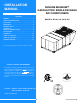
INSTALLATION MANUAL SUNLINE MAGNUM™ GAS/ELECTRIC SINGLE PACKAGE AIR CONDITIONERS CONTENTS GENERAL . . . . . . . . . . . . . . . . . . . . . . . . . . . . . . . . . . . .4 SAFETY CONSIDERATIONS . . . . . . . . . . . . . . . . . . . . .4 MODELS: DJ180, 210, 240 & 300 INSPECTION . . . . . . . . . . . . . . . . . . . . . . . . . . . . . . . . . .4 REFERENCE . . . . . . . . . . . . . . . . . . . . . . . . . . . . . . . . . .4 RENEWAL PARTS . . . . . . . . . . . . . . . . . . . . . . . . . . . . .
175231-YIM-A-0706 TABLE OF CONTENTS GENERAL . . . . . . . . . . . . . . . . . . . . . . . . . . . . . . . . . . . . . . . . 4 SAFETY CONSIDERATIONS . . . . . . . . . . . . . . . . . . . . . . . . . 4 INSPECTION . . . . . . . . . . . . . . . . . . . . . . . . . . . . . . . . . . . . . . 4 REFERENCE . . . . . . . . . . . . . . . . . . . . . . . . . . . . . . . . . . . . . . 4 RENEWAL PARTS . . . . . . . . . . . . . . . . . . . . . . . . . . . . . . . . . 5 APPROVALS . . . . . . . . . . . . . . . . . . . . .
175231-YIM-A-0706 LIST OF FIGURES Fig. # LIST OF TABLES Pg. # Tbl. # Pg. # 1 TYPICAL RIGGING . . . . . . . . . . . . . . . . . . . . . . . . . . . . . . . 9 1 UNIT APPLICATION DATA . . . . . . . . . . . . . . . . . . . . . . . . 8 2 CENTER OF GRAVITY . . . . . . . . . . . . . . . . . . . . . . . . . . . . 9 2 CONTROL WIRE SIZES . . . . . . . . . . . . . . . . . . . . . . . . . . 13 3 FIXED OUTDOOR AIR DAMPER . . . . . . . . . . . . . . . . . . . 11 3 ELECTRIC HEAT APPLICATION DATA . . . . . . . .
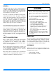
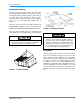
175231-YIM-A-0706 GENERAL YORK Model DJ units are either single package air conditions equipped with optional factory installed electric heaters, or single package gas-fired central heating furnaces with cooling unit. Both are designed for outdoor installation on a rooftop or slab. FIRE OR EXPLOSION HAZARD Failure to follow safety warnings exactly could result in serious injury, death, or property damage. The units are completely assembled on rigid, permanently attached base rails.
175231-YIM-A-0706 RENEWAL PARTS Contact your local York® Parts Distribution Center for authorized replacement parts. APPROVALS Design certified by CSA as follows: • For use as a cooling unit only with or without optional electric heat. • For use as a forced air furnace with cooling unit • For outdoor installation only. • For installation on combustible material. • For use with natural gas or propane gas.
175231-YIM-A-0706 PRODUCT NOMENCLATURE 15-25 Ton Magnum™ Model Number Nomenclature D J 180 N24 A 2 A AA 1 0 1 2 4 A Product Category Product Style D = A/C, Single Pkg., R-22 A = Style A Product Identifier Configuration Options (not required for all units) These four digits will not be assigned until a quote is requested, or an order placed. J = 11.
175231-YIM-A-0706 INSTALLATION LIMITATIONS INSTALLATION SAFETY INFORMATION: These units must be installed in accordance with the following national and local safety codes: Read these instructions before continuing this appliance installation. This is an outdoor combination heating and cooling unit. The installer must assure that these instructions are made available to the consumer and with instructions to retain them for future reference. In U.S.A.: • National Electrical Code ANSI/NFPA No. 70.
175231-YIM-A-0706 TABLE 1: UNIT APPLICATION DATA UNIT MODEL NUMBER 208/230-3-60 Voltage Varation, Min. 460-3-60 1 / Max. 575-3-60 Supply Air CFM, Min. / Max. Wet bulb Temperature (0F) of Air on Evaporator Coil, Min. / Max. Dry bulb Temperature (0F) of Air on Condenser Coil, Min. / Max. DJ180 DJ210 DJ240 DJ300 6,000 / 9,400 7,500 / 12,500 187 / 253 414 / 506 518 / 630 4,500 / 7,000 6,000 / 8,750 57 / 72 0 / 125 1.
175231-YIM-A-0706 RIGGING AND HANDLING Exercise care when moving the unit. Do not remove any packaging until the unit is near the place of installation. Rig the unit by attaching chain or cable slings to the round lifting holes provided in the base rails. Spreaders, whose length exceeds the largest dimension across the unit, MUST BE USED. Refer to Figure 1. Units may also be moved or lifted with a forklift, from the side only, providing that an accessory skid is used.
175231-YIM-A-0706 FIXED OUTDOOR AIR INTAKE DAMPER Do not permit overhanging structures or shrubs to obstruct outdoor air discharge outlet, combustion air inlet or vent outlets. DUCTWORK Ductwork should be designed and sized according to the methods in Manual Q of the Air Conditioning Contractors of America (ACCA). A closed return duct system shall be used. This shall not preclude use of economizers or outdoor fresh air intake.
175231-YIM-A-0706 COMPRESSORS Units are shipped with compressor mountings factoryadjusted and ready for operation. Do not loosen compressor mounting bolts. FILTERS FIGURE 3 - FIXED OUTDOOR AIR DAMPER CONDENSATE DRAIN Two-inch filters are supplied with each unit, but units can be converted easily to four-inch filters. Filters must always be installed ahead of the evaporator coil and must be kept clean or replaced with same size and type.
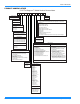
175231-YIM-A-0706 T H ER M O S T AT 1 T E RM I N A LS UNIT CONTROL BOARD R C R H R Y 1 Y 1 Y 2 Y 2 W 1 W 1 W 2 W 2 G G C C X 1 X X 3 2 2 4 V ol t T ra ns fo rm e r O CC X 4 A 1 A 2 T T T O R EM O T E S EN S OR 2 ET 04 7 0 13 2 4 IF U SE D E le ct r o ni c p ro g ra mm a bl e T he rm o s ta t 2 E T0 77 00 10 02 4 ( in c
175231-YIM-A-0706 with a separate branch circuit fed directly from the meter panel and properly fused. THERMOSTAT The room thermostat should be located on an inside wall approximately 56 inches above the floor where it will not be subject to drafts, sun exposure or heat from electrical fixtures or appliances. Follow manufacturer's instructions enclosed with thermostat for general installation procedure. A minimum of seven color-coded insulated wires (#18 AWG) should be used to connect thermostat to unit.
175231-YIM-A-0706 OPTIONAL GAS HEAT These gas-fired heaters have aluminized-steel or optional stainless steel, tubular heat exchangers with spark ignition with proven pilot. All gas heaters are shipped from the factory equipped for natural gas use, but can be field converted to L.P./ Propane with Kit Model # 1NP0418. See Gas Heat Application Data Table.
175231-YIM-A-0706 supply piping system at test pressures equal to or less than 1/2 psig (3.48kPa). Natural gas may contain some propane. Propane, being an excellent solvent, will quickly dissolve white lead or most standard commercial compounds. Therefore, a special pipe compound must be applied when wrought iron or steel pipe is used. Shellac base compounds such as Gaskolac or Stalastic, and compounds such as Rectorseal #5, Clyde's or John Crane may be used. 7.
175231-YIM-A-0706 For satisfactory operation, L.P./propane gas pressure must be 10.0 I.W.C. at the unit manifold under full load. Maintaining proper gas pressure depends on three main factors: 1. The vaporization rate depends on (a) the temperature of the liquid and (b) the "wetted surface" area of the container or containers. 2. The proper pressure regulation. (Two-stage regulation is recommended from the standpoint of both cost and efficiency.) 3.
5231-YIM-A-0706 control module) to the "A", "B", "C" or "D" setting corresponding to the lettered curve of the Enthalpy Setpoint Adjustment Figure 9. OPTIONAL POWER EXHAUST/BAROMETRIC RELIEF DAMPER RAIN HOOD The instructions for the power exhaust/barometric relief damper rain hood can be found in the kit. The exhaust fan, all supporting brackets, angles, and the wiring are factory installed as part of the power exhaust option.
175231-YIM-A-0706 FIGURE 9 - ENTHALPY SETPOINT ADJUSTMENT 18 Unitary Products Group
175231-YIM-A-0706 Exhaust Air Adjustment Screw Exhaust Air LED Damper Min. Position Screw Indoor Air Quality Max. Adjustment Screw N1 P1 T1 N EXH Set TR P EXH 24 Vac HOT T Min Pos AQ1 AQ 24 Vac COM + IAQ Max Indoor Air Quality LED TR1 1 2 IAQ 5 Indoor Air Quality Min.
175231-YIM-A-0706 TABLE 6: FOUR AND SIX POINT LOADS Unit Size 180 Gas 210 Gas 240 Gas 300 Gas 180 Elec 210 Elec 240 Elec 300 Elec Unit Size 180 Gas 210 Gas 240 Gas 300 Gas 180 Elec 210 Elec 240 Elec 300 Elec Total Shipping Weight 2660 2928 2960 3046 2460 2728 2760 2846 Total Shipping Weight 2660 2928 2960 3046 2460 2728 2760 2846 4 Point Loads (lbs) A B C D 454 510 516 531 419 476 481 496 847 954 964 992 784 888 899 927 885 954 964 992 819 888 899 927 474 510 516 531 438 476 481 496 6 Point Loa
175231-YIM-A-0706 TABLE 7: PHYSICAL DATA MODELS EVAPORATOR BLOWER ACCESSORIES OPTIONS CENTRIFUGAL BLOWER (Dia.x Wd.) FAN MOTOR HP ROWS DEEP EVAPORATOR FINS PER INCH COIL FACE AREA (Sq. Ft.) PROPELLER DIA. (In.) (Each) CONDENSER FAN FAN MOTOR HP (Each) (Four Per Unit) NOM. CFM TOTAL (Each) ROWS DEEP CONDENSER FINS PER INCH COIL FACE AREA (Sq. Ft.) COMPRESSOR SCROLL (Qty. Per Unit) QUANTITY PER UNIT (12" X 24" X 2") FILTERS TOTAL FACE AREA (Sq. Ft.) REFRIGANT 22 SYSTEM No.1 CHARGE (Lb./Oz.) SYSTEM No.
175231-YIM-A-0706 TABLE 8: DJ ELECTRICAL DATA WITHOUT POWERED CONVENIENCE OUTLET COMPRESSORS MODEL (TONNAGE) VOLTAGE RLA EACH LRA EACH ID CONV OD FAN BLOWER MOTORS MOTOR OUTLET AMPS MODEL FLA EACH FLA 208 22.4 164 2.1 15.4 0.0 230 22.4 164 2.1 15.4 0.0 460 10.9 100 1.1 7.2 0.0 575 8.3 78 0.9 5.9 0.0 208 25.6 190 2.1 20.0 0.0 230 25.6 190 2.1 20.0 0.0 460 12.8 95 1.1 10.0 0.0 575 10.3 75 0.9 8.2 0.
175231-YIM-A-0706 TABLE 8: DJ ELECTRICAL DATA WITHOUT POWERED CONVENIENCE OUTLET (CONTINUED) COMPRESSORS MODEL (TONNAGE) VOLTAGE RLA EACH LRA EACH ID CONV OD FAN BLOWER MOTORS MOTOR OUTLET AMPS MODEL FLA EACH FLA 208 33.6 225 3.7 20.0 0.0 230 33.6 225 3.7 20.0 0.0 460 17.3 114 1.9 10.0 0.0 575 13.5 80 1.5 8.2 0.0 208 47.1 245 3.7 38.6 0.0 230 47.1 245 3.7 38.6 0.0 460 19.6 125 1.9 19.3 0.0 575 15.8 100 1.5 15.4 0.
175231-YIM-A-0706 TABLE 9: DJ ELECTRICAL DATA WITH POWERED CONVENIENCE OUTLET COMPRESSORS MODEL (TONNAGE) VOLTAGE RLA EACH LRA EACH ID CONV OD FAN BLOWER MOTORS MOTOR OUTLET AMPS MODEL FLA EACH FLA 208 22.4 164 2.1 15.4 10.0 230 22.4 164 2.1 15.4 10.0 460 10.9 100 1.1 7.2 5.0 575 8.3 78 0.9 5.9 4.0 208 25.6 190 2.1 20.0 10.0 230 25.6 190 2.1 20.0 10.0 460 12.8 95 1.1 10.0 5.0 575 10.3 75 0.9 8.2 4.
175231-YIM-A-0706 TABLE 9: DJ ELECTRICAL DATA WITH POWERED CONVENIENCE OUTLET (CONTINUED) COMPRESSORS MODEL (TONNAGE) VOLTAGE RLA EACH LRA EACH ID CONV OD FAN BLOWER MOTORS MOTOR OUTLET AMPS MODEL FLA EACH FLA 208 33.6 225 3.7 20.0 10.0 230 33.6 225 3.7 20.0 10.0 460 17.3 114 1.9 10.0 5.0 575 13.5 80 1.5 8.2 4.0 208 47.1 245 3.7 38.6 10.0 230 47.1 245 3.7 38.6 10.0 460 19.6 125 1.9 19.3 5.0 575 15.8 100 1.5 15.4 4.
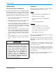
175231-YIM-A-0706 ECONOMIZER / MOTORIZED DAMPER FIXED OUTDOOR INTAKE AIR AND POWER EXHAUST RAIN HOODS (See detail Y) BLOWER COMPARTMENT ACCESS (Auxiliary) DOT PLUG (For pressure drop reading) BLOWER MOTOR ACCESS BLOWER ACCESS COMPRESSOR ACCESS 180-19/32 52-5/8 GAS OR ELECTRIC HEAT ACCESS COIL GUARD KIT VENT AIR OUTLET HOODS COMBUSTION AIR INLET HOOD 21.
175231-YIM-A-0706 EVAPORATOR SECTION DOT PLUG (For pressure drop reading) 40-3/8" FILTER ACCESS SUPPLY AIR RETURN AIR COMPRESSOR ACCESS OUTDOOR AIR 40-1/2" SUPPLY AIR ACCESS Dimensions listed are for side duct flange openings; see Field Accessories for Side Duct Flange Kit. 18-5/8" 1" NPT FEMALE COND.
175231-YIM-A-0706 NOTE: ELEC / ELEC Models: Units and ductwork are approved for zero clearance to combustible material when equipped with electric heaters. CLEARANCES LOCATION CLEARANCE Front 36” Rear 24” (Less Economizer) 49” (With Economizer) Left Side (Filter Access) 24” (Less Economizer) 36” (With Economizer)3 Right Side (Cond.
175231-YIM-A-0706 CFM, STATIC PRESSURE, AND POWER - ALTITUDE AND TEMPERATURE CORRECTIONS order to use the indoor blower tables for high altitude applications, certain corrections are necessary. The information below should be used to assist in application of product when being applied at altitudes at or exceeding 1000 feet above sea level. A centrifugal fan is a "constant volume" device. This means that, if the rpm remains constant, the CFM delivered is the same regardless of the density of the air.
175231-YIM-A-0706 FIGURE 16 - ALTITUDE/TEMPERATURE CONVERSION FACTOR 30 Unitary Products Group
175231-YIM-A-0706 TABLE 11: SUPPLY AIR BLOWER PERFORMANCE (15 TON) - COOLING ONLY 180 MBH - BOTTOM DUCT CONNECTIONS BLOWER SPEED, (RPM) MOTOR PULLEY (TURNS OPEN)* CFM 4500 ESP BHP 5250 KW ESP BHP 6000 KW ESP BHP 6750 KW ESP BHP 7200 KW ESP BHP KW 208 VOLT AND STANDARD DRIVE 850 6.0** 0.9 2.4 2.2 0.7 3.0 2.7 0.5 3.2 2.9 - - - - - - 870 5.5 1.0 2.5 2.3 0.8 3.1 2.8 0.6 3.5 3.1 0.2 4.1 3.7 - - - 915 4.5 1.1 2.6 2.4 0.9 3.4 3.0 0.7 3.7 3.3 0.3 4.
175231-YIM-A-0706 . TABLE 12: SUPPLY AIR BLOWER PERFORMANCE (17.5 TON) - COOLING ONLY 210 MBH - BOTTOM DUCT CONNECTIONS BLOWER SPEED, (RPM) MOTOR PULLEY (TURNS OPEN)* CFM 6000 ESP 7000 8000 BHP KW ESP BHP KW ESP BHP 9000 KW ESP BHP KW 208 VOLT AND STANDARD DRIVE 870 6.0** 0.4 2.1 1.8 0.1 2.3 2.0 - - - - - - 900 5.0 0.8 3.2 2.7 0.5 3.5 2.9 0.2 3.8 3.2 - - - 930 4.0 1.1 4.1 3.4 0.9 4.5 3.8 0.6 4.9 4.1 0.1 5.1 4.3 950 3.0 1.3 4.6 3.9 1.1 5.1 4.
175231-YIM-A-0706 TABLE 13: SUPPLY AIR BLOWER PERFORMANCE (20 TON) - COOLING ONLY 240 MBH - BOTTOM DUCT CONNECTIONS BLOWER SPEED, (RPM) MOTOR PULLEY (TURNS OPEN)* CFM 6000 ESP 7000 8000 BHP KW ESP BHP KW ESP BHP 9000 9400 KW ESP BHP KW ESP BHP KW - 208 VOLT AND STANDARD DRIVE 870 6.0** 0.4 2.1 1.8 0.1 2.3 2.0 - - - - - - - - 900 5.0 0.8 3.2 2.7 0.5 3.5 2.9 0.2 3.8 3.2 - - - - - - 930 4.0 1.1 4.1 3.4 0.9 4.5 3.8 0.6 4.9 4.1 0.1 5.1 4.
175231-YIM-A-0706 TABLE 14: SUPPLY AIR BLOWER PERFORMANCE (15 TON) - GAS HEAT 180 MBH - BOTTOM DUCT CONNECTIONS BLOWER SPEED, (RPM) MOTOR PULLEY (TURNS OPEN)* CFM 4500 ESP BHP 5250 KW ESP BHP 6000 KW ESP BHP 6750 KW ESP BHP 7200 KW ESP BHP KW 208 VOLT AND STANDARD DRIVE 850 6.0** 0.9 2.4 2.1 0.6 2.9 2.6 0.3 3.4 3.0 - - - - - - 870 5.5 1.0 2.5 2.2 0.7 3.0 2.7 0.4 3.5 3.1 - - - - - - 915 4.5 1.1 2.6 2.4 0.8 3.1 2.8 0.5 3.6 3.2 0.2 4.1 3.
175231-YIM-A-0706 TABLE 15: SUPPLY AIR BLOWER PERFORMANCE (17.5 TON) - GAS HEAT 210 MBH - BOTTOM DUCT CONNECTIONS BLOWER SPEED, (RPM) MOTOR PULLEY (TURNS OPEN)* CFM 6000 ESP 7000 8000 9000 BHP KW ESP BHP KW ESP BHP KW ESP BHP KW - 208 VOLT AND STANDARD DRIVE 870 6.0** 1.3 3.6 3.0 0.7 4.3 3.7 0.2 5.1 4.3 - - 900 5.0 1.4 3.8 3.2 0.9 4.7 4.0 0.4 5.6 4.7 - - - 930 4.0 1.6 4.1 3.4 1.1 5.0 4.2 0.6 5.9 5.0 0.1 6.7 5.7 950 3.0 1.7 4.2 3.6 1.3 5.1 4.
175231-YIM-A-0706 TABLE 16: SUPPLY AIR BLOWER PERFORMANCE (20 TON) - GAS HEAT 240 MBH - BOTTOM DUCT CONNECTIONS BLOWER SPEED, (RPM) MOTOR PULLEY (TURNS OPEN)* CFM 6000 ESP BHP 7000 KW ESP BHP 8000 KW ESP BHP 9000 KW ESP BHP 9400 KW ESP BHP KW 208 VOLT AND STANDARD DRIVE 870 6.0** 1.3 3.6 3.0 0.7 4.3 3.7 0.2 5.1 4.3 - - - - - - 900 5.0 1.4 3.8 3.2 0.9 4.7 4.0 0.4 5.6 4.7 - - - - - - 930 4.0 1.6 4.1 3.4 1.1 5.0 4.2 0.6 5.9 5.0 0.1 6.7 5.
175231-YIM-A-0706 TABLE 17: SUPPLY AIR BLOWER PERFORMANCE (25 TON) - GAS HEAT 300 MBH - BOTTOM DUCT CONNECTIONS BLOWER SPEED, (RPM) MOTOR PULLEY (TURNS OPEN)* CFM 7500 ESP BHP 8750 KW ESP BHP 10000 KW ESP BHP 11250 KW ESP BHP 12500 KW ESP BHP KW 208 VOLT AND STANDARD DRIVE 975 6.0 1.2 5.9 4.9 5.0 7.3 6.0 - - - - - - - - - 1005 5.0 1.4 6.2 5.1 0.7 7.7 6.3 - - - - - - - - - 1040 4.0 1.6 6.6 5.4 0.9 8.1 6.7 0.2 9.7 8.0 - - - - - - 1070 3.
175231-YIM-A-0706 TABLE 18: STATIC RESISTANCES1 RESISTANCE, IWG CFM DESCRIPTION 15 TON 25 TON 6000 7200 6000 7500 9000 6000 8000 9400 7500 10000 0.1 0.1 0.1 0.1 0.1 0.1 0.1 0.1 0.1 0.11 0.11 0.11 18 KW 0.1 0.1 0.1 0.1 0.1 0.1 0.1 0.1 0.1 0.31 0.56 0.87 36 KW 0.1 0.2 0.3 0.1 0.2 0.3 0.1 0.2 0.3 0.38 0.68 1.07 54 KW 0.2 0.3 0.4 0.2 0.3 0.4 0.2 0.3 0.4 0.62 1.10 1.72 72 KW 0.2 0.4 0.6 0.2 0.4 0.6 0.2 0.4 0.6 0.68 1.21 1.90 0.1 0.
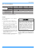
175231-YIM-A-0706 15 Ton Charging Chart Outdoor Temp Discharge Pressure (psi) 400 350 115 º 300 105º 95º 250 85º 200 75º 150 100 60 70 80 90 100 Suction Pressure (psi) 1. Make sure that both condenser fans are running w hen charging. One fan may sw itch off at low er ambient temperatures making the chart above inaccurate. 2. This chart is applicable to unit w ith the TXV's left to the factory setting. If the TXV's have been adjusted in the field, The charging chart may no longer apply.
175231-YIM-A-0706 20 Ton Charging Chart Outdoor Temp (ºF) Discharge Pressure (psi) 400 350 115º 300 105º 95º 85º 75º 65º 250 200 150 100 60 65 70 75 80 85 90 Suction Pressure (psi) 95 100 1. Make sure that both condenser fans are running when charging. One fan may switch off at lower ambient temperatures making the chart above inaccurate. 2. This chart is applicable to unit with the TXV's left to the factory setting.
175231-YIM-A-0706 PHASING Note the following: YORK MODEL DJ, units are properly phased at the factory. Check for proper compressor rotation. If the blower or compressors rotate in the wrong direction at start-up, the electrical connection to the unit is misphased. Change the incoming line connection phasing to obtain proper rotation. (Scroll compressors operate in only one direction.
175231-YIM-A-0706 AIR BALANCE Start the supply air blower motor. Adjust the resistances in both the supply and the return air duct systems to balance the air distribution throughout the conditioned space. The job specifications may require that this balancing be done by someone other than the equipment installer. 4. Knowing the pressure drop across a dry coil, the actual CFM through the unit can be determined from the curve in Pressure Drop vs. Supply Air CFM Figure 22.
175231-YIM-A-0706 COOLING SEQUENCE OF OPERATION ECONOMIZER WITH SINGLE ENTHALPY SENSOR - CONTINUOUS BLOWER When the room thermostat calls for "first-stage" cooling, the low voltage control circuit from "R" to "G" and "Y1" is completed. The UCB energizes the blower motor (if the fan switch on the room thermostat is set in the "AUTO" position) and drives the economizer dampers from fully closed to their minimum position.
175231-YIM-A-0706 exhaust fan setpoint on the economizer control. When the power exhaust is operating, the second stage of mechanical cooling will not operate. As always, the "R" to "G" connection provides minimum position but does not provide power exhaust operation. associated compressor, initiate the ASCD, and, if the other compressor is idle, stop the condenser fans. If the call for cooling is still present at the conclusion of the ASCD, the UCB will re-energize the halted compressor.
175231-YIM-A-0706 SAFETY CONTROLS RESET The unit control board monitors the following inputs for each cooling system: Remove the call for cooling, by raising thermostat setting higher than the conditioned space temperature. This resets any pressure or freezestat flash codes. 1. A suction line freezestat to protect against low evaporator temperatures due to a low airflow or a low return air temperature, (opens at 26 ± 5 °F and resets at 38 ± 5°F). 2.
175231-YIM-A-0706 This limit is monitored regardless of unit operation status, i.e. the limit is monitored at all times. If the temperature limit opens three times within one hour, it will lock-on the indoor blower motor and a flash code is initiated (See Table 26). FLASH CODES The UCB will initiate a flash code associated with errors within the system. Refer to UNIT CONTROL BOARD FLASH CODES Table 26.
175231-YIM-A-0706 motor shaft, closes to power the first stage ignition module "IC1", thru the "RW1-1 contacts. Ignition module "IC1" will immediately start the first stage igniter sparking and will open the redundant valve located inside the first stage main gas valve "GV1" to allow a flow of gas to only the first stage carryover tube.
175231-YIM-A-0706 GAS VALVE The UCB continuously monitors the GV. Any time the UCB senses voltage at the GV without a call for heat for a continuous five-minute period, the UCB will lockon the indoor blower and a flash code is initiated (Table 26). When voltage is no longer sensed at the GV, the UCB will de-energize the indoor blower following the elapse of the fan off delay for heating.
175231-YIM-A-0706 START-UP (COOLING) PRESTART CHECK LIST IG N . C O N T R O L # 2 After installation has been completed: IG N . C O N T R O L # 1 1. Check the electrical supply voltage being supplied. Be sure that it is the same as listed on the unit nameplate. R O L L O U T S W . G V 1 G A S V A L V E S E N S O R # 1 G V 2 G A S V A L V E IG N IT O R # 2 2. Set the room thermostat to the off position. IG N IT O R # 1 3. Turn unit electrical power on. S E N S O R # 2 4.
175231-YIM-A-0706 3. Measure the system Amperage draw across all legs of 3 phase power wires. 4. Measure the condenser fan amp draw. POST-START CHECK LIST (GAS) After the entire control circuit has been energized and the heating section is operating, make the following checks: SHUT DOWN 1. Set the thermostat to highest temperature setting. 1. Check for gas leaks in the unit piping as well as the supply piping. 2. Turn off the electrical power to the unit.
175231-YIM-A-0706 MANIFOLD GAS PRESSURE ADJUSTMENT Put the system into operation and observe through complete cycle to be sure all controls function properly. Small adjustments to the high-fire gas flow may be made by turning the pressure regulator adjusting screw on the automatic gas valve. BURNER INSTRUCTIONS Adjust as follows: To check or change burners, pilot or orifices, CLOSE MAIN MANUAL SHUT-OFF VALVE AND SHUT OFF ALL ELECTRIC POWER TO THE UNIT. 1. Remove the cap on the regulator.
175231-YIM-A-0706 CHECKING GAS INPUT ADJUSTMENT OF TEMPERATURE RISE NATURAL GAS The temperature rise (or temperature difference between the return air and the heated air from the furnace) must lie within the range shown on the rating plate and the data in the Gas Heat Application Table 4. 1. Turn off all other gas appliances connected to the gas meter. 2. With the furnace turned on, measure the time needed for one revolution of the hand on the smallest dial on the meter.
175231-YIM-A-0706 Label all wires prior to disconnection when servicing controls. Wiring errors can cause improper and dangerous operation, which could cause injury to person and/or damage unit components. Verify proper operation after servicing. On calls for cooling, if the compressors are operating but the supply air blower motor does not energize after a short delay (the room thermostat fan switch is in the “AUTO” position). 1. Turn the thermostat fan switch to the ON position.
175231-YIM-A-0706 5. Failing the above, if voltage is supplied at M1, M1 is pulled in, and the compressor still does not operate, replace the compressor. 6. If 24 volts is not present at M1, check for 24 volts at the UCB terminal, C1. If 24 volts is present, check for loose wiring between C1 and the compressor contactor. 7. If 24 volts is not present at the C1 terminal, check for 24 volts from the room thermostat at the UCB Y1 terminal.
175231-YIM-A-0706 14. The UCB can be programmed to lock out compressor operation during free cooling and in low ambient conditions. These options are not enabled by default. Local distributors can test the UCB for this programming. For units with factory installed economizers, the UCB is programmed to lock out compressor operation when the LAS set point is reached. For units without factory installed or with field installed economizers, the UCB allows compressor operation all the time.
175231-YIM-A-0706 11. The UCB can be programmed to lock out compressor operation during free cooling and in low ambient conditions. These options are not enabled by default. Local distributors can test the UCB for this programming. For units with factory installed economizers, the UCB is programmed to lock out compressor operation when the LAS set point is reached. For units without factory installed or with field installed economizers, the UCB allows compressor operation all the time.
175231-YIM-A-0706 present at the Y1 “OUT” terminal, the UCB must be replaced. 12. For units without economizers: If 24 volts is present at the Y1 “OUT” terminal, check for 24 volts at the Y1 “ECON” terminal. If 24 volts is not present, check for loose wiring from the Y1 “OUT” terminal to the Mate-N-Lock plug, the jumper in the Mate-NLock plug, and in the wiring from the Mate-N-Lock plug to the Y1 “ECON” terminal.
175231-YIM-A-0706 1. Place the thermostat fan switch in the “ON” position. If the supply air blower motor energizes, go to Step 9. nace has ignited when the fan switch is in the “AUTO” position, check the room thermostat for contact between R and G during “W1” calls. 2. If the supply air blower motor does not energize when the fan switch is set to “ON,” check that line voltage is being supplied to the contacts of the M3 contactor, and that the contactor is pulled in.
175231-YIM-A-0706 4. If the furnace is cold, check for 24 volts at wire 241 attached to the electrical time delay (ETD) located in the main control box. If 24 volts is not found, replace the ETD. 5. 24 volts is found at wire 241, remove the wires attached to the (TDR) and with a VOM, check for continuity across contacts 1 and 2. If none is found, the (TDR) is open and must be replaced. If there is continuity, re-attach the wires.
175231-YIM-A-0706 2. Make sure that the carryovers on adjoining burners are screwed fast and are level with respect to one another. Main burners light but exhibit erratic flame characteristics. 1. Adjust air shutters as described in “BURNER AIR SHUTTER ADJUSTMENT” page 51. 2. Check the main burner orifices for obstruction and alignment. Removal procedure is described in BURNER INSTRUCTIONS page 51. Clean or replace burner orifices and burners as needed.
175231-YIM-A-0706 TABLE 26: UNIT CONTROL BOARD FLASH CODES FLASH CODE On Steady 1 Flash DESCRIPTION GREEN LED 16 RED LED 8 RED LED 4 RED LED 2 RED LED 1 This is a Control Failure - - - - - Not Applicable - - - - - Flashing Off Off On Off On 2 Flashes Control waiting ASCD1 3 Flashes HPS1 Compressor Lockout Off Off Off On 4 Flashes HPS2 Compressor Lockout Off Off On Off Off 5 Flashes LPS1 Compressor Lockout Off Off On Off On 6 Flashes LPS2 Compressor Lockout Of
175231-YIM-A-0706 62 Unitary Products Group
175231-YIM-A-0706 Unitary Products Group 63
Subject to change without notice. Printed in U.S.A. Copyright © 2006 by Unitary Products Group. All rights reserved.