AIR-COOLED SCREW LIQUID CHILLERS INSTALLATION, OPERATION & MAINTENANCE New Release Form 201.
FORM 201.19-NM1 (204) CHANGEABILITY OF THIS DOCUMENT In complying with YORK’s policy for continuous product improvement, the information contained in this document is subject to change without notice. Literature updates that may occur will be printed on the Revision Sheet and included with the Installation, Operation & Maintenance (IOM) man, which is provided with new equipment.
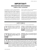
FORM 201.19-NM1 (204) IMPORTANT! READ BEFORE PROCEEDING! GENERAL SAFETY GUIDELINES This equipment is a relatively complicated apparatus. During installation, operation, maintenance or service, individuals may be exposed to certain components or conditions including, but not limited to: refrigerants, oils, materials under pressure, rotating components, and both high and low voltage. Each of these items has the potential, if misused or handled improperly, to cause bodily injury or death.
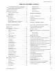
FORM 201.19-NM1 (204) TABLE OF CONTENTS SECTION 1 - GENERAL CHILLER INFORMATION & SAFETY INTRODUCTION ...........................................................9 WARRANTY...................................................................9 SAFETY...........................................................................9 Standards for Safety ...............................................9 RESPONSIBILITY FOR SAFETY...............................10 ABOUT THIS MANUAL..........................................
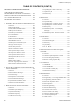
FORM 201.19-NM1 (204) TABLE OF CONTENTS (CONT’D) Units with Single-Point Power Supply Wiring ....34 115VAC CONTROL SUPPLY TRANSFORMER ........34 Remote Emergency Stop Device..........................35 CONTROL PANEL WIRING........................................35 VOLTS FREE CONTACTS ..........................................35 Chilled Liquid Pump Starter ................................35 Run Contact..........................................................35 Alarm Contacts................................
FORM 201.19-NM1 (204) TABLE OF CONTENTS (CONT’D) SECTION 8 - MICRO PANEL CONTENTS CHILLERLER CONTROL PANEL PROGRAMMING AND DATA ACCESS KEYS ....... 122 DISPLAY AND STATUS INFORMATION KEYS .... 122 ON / OFF ROCKER SWITCH.................................... 122 PROGRAM & SETUP KEYS ..................................... 122 1. INTRODUCTION & PHYSICAL DESCRIPTION 123 1.1 General ......................................................... 123 1.2 Keypad & Display ........................................ 123 1.
FORM 201.19-NM1 (204) TABLE OF CONTENTS (CONT’D) SECTION 11 - TROUBLE SHOOTING SECTION 9 - MAINTENANCE GENERAL REQUIREMENTS ...................................194 CONDENSER COILS .................................................194 Chiller / Compressor Operating Log ..................195 Scheduled Maintenance......................................195 ON-BOARD BATTERY BACK-UP ...........................195 OVERALL UNIT INSPECTION ................................195 COMPRESSOR UNIT OPERATION .................
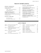
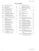
FORM 201.19-NM1 (204) LIST OF FIGURES FIG. 1 – COMPONENT LOCATIONS ......................... 12 FIG. 2 – SCREW COMPRESSOR................................ 13 FIG. 3 – UNIT RIGGING..............................................28 FIG. 4 – LIFTING LUGS .............................................. 28 FIG. 5 – COMPRESSOR MOUNTING........................ 30 FIG. 7 – VICTAULIC GROOVE .................................. 33 FIG. 8 – FLANGE ATTACHMENTS ........................... 33 FIG. 9 – POWER PANEL SECTION.....
FORM 201.19-NM1 (204) GENERAL CHILLER INFORMATION & SAFETY 1 INTRODUCTION YORK YCAS chillers are manufactured to the highest design and construction standards to en sure high performance, reliability and adaptability to all types of air conditioning installations. The unit is intended for cooling water or glycol solutions and is not suitable for purposes other than those specified in this manual.
General Chiller Information & Safety FORM 201.19-NM1 (204) RESPONSIBILITY FOR SAFETY MISUSE OF EQUIPMENT Every care has been taken in the design and manufacture of the unit to ensure compliance with the safety requirements listed above. However, the individual operating or working on any machinery is primarily responsible for: Suitability for Application The unit is intended for cooling water or glycol solutions and is not suitable for purposes other than those specified in these instructions.
FORM 201.19-NM1 (204) personnel. No attempt should be made to gain access to the control panel or electrical enclosures during normal operation of the unit. Rotating Parts Fan guards must be fitted at all times and not removed unless the power supply has been isolated. If ductwork is to be fitted, requiring the wire fan guards to be removed, alternative safety measures must be taken to protect against the risk of injury from rotating fans.
Product Description FORM 201.19-NM1 (204) PRODUCT DESCRIPTION 1 2 3 4 5 6 7 8 9 10 System Fans System 1 Power Panel System 2 Power Panel Control Panel Power Entry System 1 Compressor Evaporator System 2 Compressor System 1 Condenser Option Box 1 2 4 3 9 10 8 7 6 FIG. 1 – COMPONENT LOCATIONS INTRODUCTION YORK YCAS chillers are designed for water or water-glycol cooling. All units are designed to be located outside on the roof of a building or at ground level.
FORM 201.19-NM1 (204) Refrigerant gas is drawn into the void created by the unmeshing of the five lobed male and seven lobed female rotor. Further meshing of the rotors closes the rotor threads to the suction port and progressively compresses the gas in an axial direction to the discharge port. The gas is compressed in volume and increased in pressure before exiting at a designed volume at the discharge end of the rotor casing.
Product Description staggered rows and mechanically expanded into corrosion resistant aluminum alloy fins with full height fin collars. They have a design working pressure of 450 PSIG (31 bar). Each coil is rested to 495 PSIG (34 bar). Multiple fans move air through the coils.
FORM 201.19-NM1 (204) Each power compartment contains: Compressor and fan starting contactors, fan motor external overloads, control circuit serving compressor capacity control, compressor and fan contactor coils and compressor motor overloads. (Fig #1, page 12) Current transformers in the 2ACE module provide compressor motor overload protection and sense each phase.
Product Description Motor Protection Modules (2ACE) The mechanical motor protector is a Texas Instruments 2ACE Three Phase Protection Module (Fig. 45, page 127), provides thermal and current motor overload protection. This module also protects against phase to phase current imbalance, over current, under current, and phase rotation. The modules, mounted in the power panels, utilizes a 7 segment display which provides operating status and fault diagnostic information.
FORM 201.19-NM1 (204) Thermal Overload Three PTC (positive temperature coefficient) thermistors in the motor windings provides thermal protection. The sensor resistance stays relatively constant at 1kΩ until a temperature of 266°F (130°C) is sensed. The sensor experiences a rapid rise in resistance beyond this temperature. Whenever the resistance of one of the sensors reaches 13kΩ, +/− 3kΩ, the 2ACE module trips, which ultimately de-energizes the motor’s pilot circuit.
Product Description FORM 201.19-NM1 (204) TABLE 1 – MOTOR PROTECTOR DIP SWITCH SETTING YCAS STYLE G, ACROSS-THE-LINE – 60 HZ MODEL NO. 130 140 0150 SYS. 1 0150 SYS. 2 0160 0170 SYS. 1 0170 SYS. 2 CHILLER VOLT NAMEPLATE CODE RLA 17 28 40 46 58 17 28 40 46 58 17 28 40 46 58 17 28 40 46 58 17 28 40 46 58 17 28 40 46 58 17 28 40 46 58 246 214 130 107 86 267 232 140 116 93 295 256 155 128 103 265 230 139 115 92 295 256 155 128 103 321 279 169 140 112 295 256 155 128 103 NO.
FORM 201.19-NM1 (204) TABLE 1 – MOTOR PROTECTOR DIP SWITCH SETTING (CONT’D) YCAS STYLE G, ACROSS-THE-LINE – 60 HZ MODEL NO. 180 200 210 SYS. 1 210 SYS. 2 230 CHILLER VOLT NAMEPLATE CODE RLA 17 28 40 46 58 17 28 40 46 58 17 28 40 46 58 17 28 40 46 58 17 28 40 46 58 321 279 169 140 112 342 298 181 149 119 374 325 197 163 130 342 298 181 149 119 374 325 197 163 130 NO.
Product Description FORM 201.19-NM1 (204) TABLE 1 – MOTOR PROTECTOR DIP SWITCH SETTING (CONT’D) YCAS STYLE G, WYE DELTA START – 60 HZ MODEL NO. 130 140 0150 SYS. 1 0150 SYS. 2 0160 0170 SYS. 1 0170 SYS. 2 CHILLER VOLT NAMEPLATE CODE RLA 17 28 40 46 58 17 28 40 46 58 17 28 40 46 58 17 28 40 46 58 17 28 40 46 58 17 28 40 46 58 17 28 40 46 58 246 214 130 107 86 267 232 140 116 93 295 256 155 128 103 265 230 139 115 92 295 256 155 128 103 321 279 169 140 112 295 256 155 128 103 NO.
FORM 201.19-NM1 (204) TABLE 1 – MOTOR PROTECTOR DIP SWITCH SETTING (CONT’D) YCAS STYLE G, WYE DELTA START – 60 HZ MODEL NO. 180 200 210 SYS. 1 210 SYS. 2 230 CHILLER VOLT NAMEPLATE CODE RLA 17 28 40 46 58 17 28 40 46 58 17 28 40 46 58 17 28 40 46 58 17 28 40 46 58 321 279 169 140 112 342 298 181 149 119 374 325 197 163 130 342 298 181 149 119 374 325 197 163 130 NO.
Product Description MOTOR STARTING Two types of compressor motor starting are available: Across-the-Line and optional Wye-Delta Open Transition Starter. Across-the-Line starters will utilize one contactor and one start relay per compressor. The optional Wye-Delta starter utilizes 4 motor contactors, a transition delay relay, a start relay, and a start-wye relay.
FORM 201.19-NM1 (204) Entry – Used to confirm Set Point changes, cancel inputs, advance day, and change AM/PM. Setpoints – For setting chilled liquid temperature, chilled liquid range, remote reset temperature range. Clock – Used to set time, daily or holiday start/stop schedule and manual override for servicing. Print – Used to display or print operating data or system fault shutdown history for last six faults. Printouts through an RS-232 port via a separate printer.
Product Description The following options provide added protection: Black fin condenser coils – Condenser coils constructed using black epoxy coated Aluminum fin stock for corrosion resistance comparable to copper fin coils in typical seashore locations. Copper fin condenser coils – Coils constructed with corrosion resistant copper fins. Not recommended in areas where units may be exposed to acid rain.
YORK INTERNATIONAL # # Tons 0130 0373 0140 0403 0150 0453 0160 0503 0170 0543 0180 0573 0200 0623 0210 0653 0230 X D B D X X B B S S Q C Q T X Q : No Option Required : Special Quote : Control Transformer Required : Control Circuit Power Terminal Strip (std) : Special Transformer Required : Standard Power Option X : MP NF Disconnects Q : MP Circuit Breakers : SP NF Disconnects : SP TB : SP Circuit Breaker : SP TB w/ Separate System Circuit Breakers : SP NF Disconnect w/ Separate System Circuit Breake
X A X T X S X X R L L X X P X X R X S X 3 Q X D Q X S D Q A S F T I P D O E U Q M X R Q X : Standard Warranty B : 1st Year Parts & Labor C : 2nd Year Parts Only D : 2nd Year Parts & Labor E : 5 Year Compressor Parts Only F : 5 Year Compressor Parts & Labor Only G : 5 Year Units Parts Only H : 5 Year Unit Parts & Labor 5 X Q : Special Fan Motors : Aluminum : Pre-Coated : Copper : Post-Coated : Special Coil : No Option : Special Quote X : TEAO Fan Motors 2 X X C X 1 X X X X X X
FORM 201.19-NM1 (204) HANDLING AND STORAGE DELIVERY AND STORAGE INSPECTION To ensure consistent quality and maximum reliability, all units are tested and inspected before leaving the factory. Standard units are shipped completely assembled and containing refrigerant under pressure. Units are shipped without export crating unless this has been specified on the Sales Order.
Handling and Storage FORM 201.19-NM1 (204) UNIT RIGGING 88" (2250mm) CORRECT! ✓ CORRECT! ✗ WRONG! WRONG! LD03514 FIG. 3 – UNIT RIGGING WRONG! CORRECT! LD03515 FIG.
FORM 201.19-NM1 (204) INSTALLATION LOCATION REQUIREMENTS To achieve optimum performance and trouble-free service, it is essential that the proposed installation site meets with the location and space requirements for the model being installed. For dimensions, weight and space requirements, including service access, refer to the Technical Data Section. It is important to ensure that the minimum service access space is maintained for cleaning and maintenance purposes.
Installation FORM 201.19-NM1 (204) Where accumulation of snow is likely, additional height must be provided under the unit to ensure normal airflow to the unit. The clearance dimensions given are necessary to maintain good airflow and ensure correct unit operation. It is also necessary to consider access requirements for safe operation and maintenance of the unit and power and control panels.
FORM 201.19-NM1 (204) VIBRATION ISOLATORS Optional sets of vibration isolators can be supplied loose with each unit. Using the Isolator tables, refer to the Technical Data Section, identify each mount and its correct location on the unit. Installation Place each mount in its correct position and lower the unit carefully onto the mounts ensuring the mount engages in the mounting holes in the unit base frame.
Installation Pipework and fittings must be separately supported to prevent any loading on the evaporator. Flexible connections are recommended which will also minimize transmission of vibrations to the building. Flexible connections must be used if the unit is mounted on anti-vibration mounts as some movement of the unit can be expected in normal operation.
FORM 201.19-NM1 (204) PIPEWORK ARRANGEMENT Figure #6 shows the suggested pipework arrangement for single unit installations. For multiple unit installations, each unit should be piped as shown. CONNECTION TYPES & SIZES For connection sizes relevant to individual models refer to the Technical Data Section. EVAPORATOR CONNECTIONS Standard chilled liquid connections on all evaporators are of the Victaulic Groove type.
Installation If the ducts from two or more fans are to be combined into a common duct, back-flow dampers should be fitted in the individual fan ducts. This will prevent recirculation of air when only one of the fans is running. Units are supplied with outlet guards for safety and to prevent damage to the fan blades. If these guards are removed to fit ductwork, adequate alternative precautions must be taken to ensure persons cannot be harmed or put at risk from rotating fan blades.
FORM 201.19-NM1 (204) Removing high voltage power to the chiller will remove the 115VAC supply voltage to the microprocessor circuitry and the evaporator heater. In cold weather, this could cause serious damage to the chiller due to evaporator freeze-up. Do not remove power unless alternate means are taken to assure operation of the evaporator heater. Remote Emergency Stop Device If required, a remote emergency stop device can be wired into the unit.
Installation FORM 201.19-NM1 (204) POWER PANEL LAYOUTS (TYPICAL) 028972-G OPTIONAL DISCONNECT SWITCH (WYE-DELTA - TYPICAL) 028973-G OPTIONAL CIRCUIT BREAKER SWITCH (ACROSS THE LINE - TYPICAL) FIG.
FORM 201.19-NM1 (204) OPTION PANEL LAYOUT (TYPICAL) LOGIC PANEL OPTION PANEL WITH SINGLE POINT TERMINAL BLOCK (OPTIONAL) 00246VIP 4 FIG.
Installation FORM 201.19-NM1 (204) LOGIC SECTION LAYOUT 60 Hz Models: 5 2 6 3 1 4 7 8 028975-G PHOTOGRAPH OF 60 HZ MODEL LOGIC SECTION ITEM 1 2 3 4 5 6 7 8 DESCRIPTION Microprocessor Board Back of Display I/O Expansion Board #1 Power Supply Board Relay Output Board #1 Relay Output Board #2 Flow Switch & Customer Connection Terminals Circuit Breakers CB1, CB2, CB3 FIG.
FORM 201.19-NM1 (204) LOGIC SECTION LAYOUT WITH CONTROL PANEL 4 028976-G FIG.
Installation FORM 201.19-NM1 (204) CUSTOMER CONNECTIONS TERMINALS 13-34 028977-G Flow Switch 13 System No. 1 Run 14 15 Current PWM 13 16 Temperature PWM 13 System No. 2 Run System No. 1 Alarm Contacts 24 Chilled Liquid Circulating Pump Start 17 Print 13 18 13 19 23 System No. 2 Alarm Contacts 25 26 27 28 29 Chiller Run 30 Isolator Auxiliary Interlock 31 32 CONNECTION POINTS FOR EMERGENCY STOPS LD03502 FIG.
FORM 201.19-NM1 (204) CUSTOMER CONNECTIONS RELAY BOARDS I/O EXPANSION BOARD TRANSFORMERS 4 SYSTEM SWITCHES CIRCUIT BREAKERS CB1, CB2, CB3 115 VAC SUPPLY MICROPROCESSOR CIRCUIT BOARD CUSTOMER CONNECTIONS (FLOW SWITCH, ALARM, RUN, ETC.) 2028978-G FIG.
Commissioning FORM 201.19-NM1 (204) COMMISSIONING PREPARATION Commissioning of this unit should only be carried out by YORK Authorized personnel. The Millennium Microcomputer Control System Operating Instructions must be read in conjunction with this section. PREPARATION – POWER OFF The following checks should be made with the customer supply/supplies to the unit switched OFF. Inspection Inspect unit for installation damage. If damage is found take action and/or repair as appropriate.
FORM 201.19-NM1 (204) Check that the tapping used conforms to the site supply voltage. After the tapping is verified, replace the lid. Switch Settings Ensure that the unit ON/OFF switch on the display door and the micro board system switches S2 through S5 are set to “0” (OFF). Set the red handled emergency stop device on the options panel to “1” (ON). For units fitted with door interlocked circuit breakers the power panel doors must be closed and the devices set to “1” (ON).
Commissioning FIRST TIME START-UP During the commissioning period there should be sufficient heat load to run the unit under stable full load operation to enable the unit controls, and system operation to be set up correctly and a commissioning log taken. Be sure that the Micro Panel is properly programmed (page 166) and the System Start-up Checklist (page 117) is completed. Interlocks Verify that liquid is flowing through the evaporator and that heat load is present.
FORM 201.19-NM1 (204) This page intentionally left blank.
Operation FORM 201.19-NM1 (204) OPERATION GENERAL DESCRIPTION NORMAL RUNNING AND CYCLING The units are designed to work independently, or in conjunction with other equipment via a YORK ISN building management system or other automated control system. When operating, the unit controls monitor the chilled liquid system temperature at the unit and take the appropriate action to maintain this temperature within desired limits.
FORM 201.19-NM1 (204) This page intentionally left blank.
Technical Data FORM 201.19-NM1 (204) TECHNICAL DATA FLOW RATE AND PRESSURE DROP CHARTS EVAPORATOR WATER PRESSURE DROP (ENGLISH UNITS) YCAS0130 - 0230 EVAPORATOR WATER PRESSURE DROP (SI UNITS) YCAS0130 - 0230 1000.00 100.00 Press Drop, kPA Press Drop, Ft H2O 100.00 10.00 C D B 10.00 B C D A A 1.00 1.00 100 Flow, GPM MODEL NUMBER YCAS 0130, 0140 0150, 0160, 0170, 0180, 0200, 0210, 0230 500 10.00 1000 LD09230A EVAPORATOR A B C D 100.00 50.
FORM 201.19-NM1 (204) TEMPERATURE AND FLOWS (ENGLISH UNITS) MODEL NUMBER YCAS 0130EC 0140EC 0150EC 0160EC 0170EC 0180EC 0200EC 0210EC 0230EC LEAVING WATER TEMPERATURE (°F) MIN.1 40 40 40 40 40 40 40 40 40 MAX.2 55 55 55 55 55 55 55 55 55 EVAPORATOR FLOW (GPM3) MIN. 138 138 200 200 200 200 250 250 250 MAX. 525 525 600 600 600 600 750 750 750 AIR ON CONDENSER (°F) MIN. 0 0 0 0 0 0 0 0 0 MAX 125 125 125 125 125 125 125 125 125 NOTES: 1. For leaving brine temperature below 40°F (4.
Technical Data FORM 201.19-NM1 (204) TEMPERATURE AND FLOWS (SI UNITS) MODEL NUMBER YCAS 0130EC 0140EC 0150EC 0160EC 0170EC 0180EC 0200EC 0210EC 0230EC LEAVING WATER TEMPERATURE (°C) MIN.1 4.4 4.4 4.4 4.4 4.4 4.4 4.4 4.4 4.4 MAX.2 12.8 12.8 12.8 12.8 12.8 12.8 12.8 12.8 12.8 Evaporator FLOW (l/s3) MIN. 8.7 8.7 12.6 12.6 12.6 12.6 15.8 15.8 15.8 MAX. 33.1 33.1 37.9 37.9 37.9 37.9 47.3 47.3 47.3 AIR ON CONDENSER (°C) MIN. -17.7 -17.7 -17.7 -17.7 -17.7 -17.7 -17.7 -17.7 -17.7 MAX 51.7 51.7 51.7 51.
FORM 201.19-NM1 (204) PHYSICAL DATA ENGLISH UNITS MODEL NUMBER YCAS 0130EC General Unit Data Unit Capacity at ARI Conditions, Tons 121.1 Number of Independent Refrigerant Circuits 2 Refrigerant Charge, R-22, Ckt.-1 / Ckt.-2, lbs. 180 / 180 Oil Charge, Ckt.-1 / Ckt.-2, gallons 5/5 Shipping Weight: Aluminum Fin Coils, lbs. 9,888 Copper Fin Coils, lbs. 11,154 Operating Weight: Aluminum Fin Coils, lbs. 10,315 Copper Fin Coils, lbs.
Technical Data FORM 201.19-NM1 (204) PHYSICAL DATA SI UNITS MODEL NUMBER YCAS 0130EC General Unit Data Unit Capacity at 6.7°C water & 35°C ambient, kW 425.7 Number of Independent Refrigerant Circuits 2 Refrigerant Charge, R-22, Ckt.-1 / Ckt.-2, kg. 82 / 82 Oil Charge, Ckt.-1 / Ckt.-2, liters 19 / 19 Shipping Weight: Aluminum Fin Coils, kg. 4,484 Copper Fin Coils, kg. 5,059 Operating Weight: Aluminum Fin Coils, kg. 4,679 Copper Fin Coils, kg.
FORM 201.19-NM1 (204) OPERATING LIMITATIONS AND SOUND POWER DATA OPERATING LIMITATIONS – ENGLISH UNITS OPERATING LIMITATIONS – SI UNITS MIN MAX LEAVING CHILLED LIQUID TEMP ( °F) 40.1 59 LEAVING CHILLED LIQUID TEMP ( °C) CHILLED WATER TEMP DIFFERENCE ( °F) 5.5 18 CHILLED WATER TEMP DIFFERENCE ( °C) 3 10 WATER SIDE PRESSURE (PSIG) 150 WATER SIDE PRESSURE (BAR) – 10 REFRIGERANT SIDE PRESSURE (PSIG) 300 REFRIGERANT SIDE PRESSURE (BAR) – 20 EVAPORATOR FLOW MODEL YCAS MIN. MAX.
Technical Data FORM 201.19-NM1 (204) ELECTRICAL DATA OPTIONAL CONTROL TRANSFORMER CIRCUIT #1 CIRCUIT # 2 MULTIPLE POINT POWER SUPPLY CONNECTION 1T Control Transformer Options: Term. Block NF Disc SW or Circ Brkr Suitable for: Y - ∆ Start and Across-The-Line-Start Options: Term. Block NF Disc SW or Circ Brkr 2 L Two field provided power supply circuits to the unit.
FORM 201.19-NM1 (204) ELECTRICAL DATA SYSTEM #2 FIELD-SUPPLIED WIRING MODEL YCAS 0130EC 0140EC 0150EC 0160EC 0170EC 0180EC 0200EC 0210EC 0230EC FIELD PROVIDED POWER SUPPLY OVER-CURRENT VOLTS MIN NF MCA1 PROTECTION DISC SW2, 9 MIN.3, 5 MAX.
Technical Data FORM 201.19-NM1 (204) ELECTRICAL DATA OPTIONAL SINGLE-POINT POWER SUPPLY CONNECTION AND INDIVIDUAL SYSTEM CIRCUIT BREAKERS Suitable for: Y - ∆ Start and Across-The-Line-Start LD05549 One field provided power supply circuit to the unit. Field con nec tions to factory pro vid ed Non-Fused Disconnect Switch (Opt), or Terminal Block (Opt). Factory connections to Circuit Breakers on Terminal Blocks in each of the two Power Panels. See page 62 for notes.
FORM 201.19-NM1 (204) ELECTRICAL DATA SYSTEM #1 MODEL YCAS 0130EC 0140EC 0150EC 0160EC 0170EC 0180EC 0200EC 0210EC 0230EC RLA 200 230 380 460 575 200 230 380 460 575 200 230 380 460 575 200 230 380 460 575 200 230 380 460 575 200 230 380 460 575 200 230 380 460 575 200 230 380 460 575 200 230 380 460 575 YORK INTERNATIONAL SYSTEM #2 COMPRESSOR DATA VOLTS 246.1 214.0 129.5 107.0 85.6 266.8 232.0 140.4 116.0 92.8 295.0 256.0 155.0 128.0 103.0 295.0 256.0 155.0 128.0 103.0 321.0 279.0 169.
Technical Data FORM 201.19-NM1 (204) ELECTRICAL DATA OPTIONAL SINGLE-POINT POWER SUPPLY CONNECTION WITH FIELD SUPPLIED CIRCUIT PROTECTION Suitable for: Y - ∆ Start and Across-The-Line-Start One field provided power supply circuit to the unit. Field con nec tions to fac to ry pro vid ed Non-Fused Disconnect Switch (Opt), or Terminal Block (Opt). Factory connections to Terminal Blocks in each of the two Power Panels. See page 62 for notes.
FORM 201.19-NM1 (204) ELECTRICAL DATA SYSTEM #1 MODEL YCAS 0130EC 0140EC 0150EC 0160EC 0170EC 0180EC 0200EC 0210EC 0230EC VOLTS 460 575 460 575 460 575 460 575 460 575 460 575 460 575 460 575 460 575 YORK INTERNATIONAL SYSTEM #2 COMPRESSOR DATA FAN DATA11, 12 RLA X-LRA QTY FLA (EA.) 107 86 116 93 128 103 128 103 140 112 140 112 149 119 163 130 163 130 719 574 719 574 893 714 893 714 893 714 893 714 893 714 893 714 893 714 4 4 4 4 4 4 4 4 4 4 4 4 5 5 5 5 5 5 4.0 3.1 4.0 3.1 4.0 3.1 4.0 3.1 4.
Technical Data FORM 201.19-NM1 (204) ELECTRICAL DATA OPTIONAL SINGLE-POINT POWER SUPPLY CONNECTION TO FACTORY CIRCUIT BREAKER Suitable for: Across-The-Line-Start One field provided power supply circuit to the unit. Field connections to factory provided Circuit Breaker in the Options Panel. Factory connections to Terminal Blocks in each of the two Power Panels. See page 62 for notes.
FORM 201.
Technical Data FORM 201.19-NM1 (204) ELECTRICAL NOTES NOTES & LEGEND LEGEND ACR-LINE C.B. D.E. DISC SW FACT CB FLA HZ MAX MCA MIN MIN NF RLA S.P.
FORM 201.19-NM1 (204) This page intentionally left blank.
Technical Data FORM 201.19-NM1 (204) WIRING DIAGRAM 7. ACROSS-THE-LINE START NOTES: 1. Field wiring to be in accordance with the current edition of the National Electrical Code as well as all other applicable codes and specifications. 2. Numbers along the right side of a diagram are line identification numbers. The numbers at each line indicate the line number location of relay contacts. An unlined contact location signifies a normally closed contact.
FORM 201.19-NM1 (204) WIRING DIAGRAM ACROSS-THE-LINE START 7 LD09233 FIG.
Technical Data FORM 201.19-NM1 (204) 3 4 6 5 ELEMENTARY DIAGRAM LD09234 FIG.
FORM 201.19-NM1 (204) ELEMENTARY DIAGRAM CAUTION: No Controls (relays, etc.) should be mounted in the Smart Panel enclosure or connected to power supplies in the control panel. Additionally, control wiring not connected to the Smart Panel should not be run through the cabinet. This could re sult in nuisance faults.
Technical Data FORM 201.19-NM1 (204) WIRING DIAGRAM 7. WYE-DELTA START NOTES: 1. Field wiring to be in accordance with the current edition of the National Electrical Code as well as all other applicable codes and specifications. 2. Numbers along the right side of a diagram are line identification numbers. The numbers at each line indicate the line number location of relay contacts. An unlined contact location signifies a normally closed contact.
FORM 201.19-NM1 (204) WIRING DIAGRAM WYE-DELTA START 7 LD09236 FIG.
Technical Data FORM 201.19-NM1 (204) 3 4 6 5 ELEMENTARY DIAGRAM LD09234 FIG.
FORM 201.19-NM1 (204) ELEMENTARY DIAGRAM CAUTION: No Controls (relays, etc.) should be mounted in the Smart Panel enclosure or connected to power supplies in the control panel. Additionally, control wiring not connected to the Smart Panel should not be run through the cabinet. This could re sult in nuisance faults.
Technical Data FORM 201.19-NM1 (204) LD09238 FIG.
FORM 201.19-NM1 (204) 7 FIG.
Technical Data FORM 201.19-NM1 (204) LD09240 FIG.
FORM 201.
Technical Data FORM 201.
FORM 201.
Technical Data FORM 201.
FORM 201.
Technical Data FORM 201.
FORM 201.19-NM1 (204) This page intentionally left blank.
Technical Data FORM 201.19-NM1 (204) DIMENSIONS – YCAS0130 - YCAS0180 (ENGLISH) 0P0.71 LD03742a P LD03742 DIMENSION P MODELS 130 - 140 17-1/4" MODELS 150 - 180 18" NOTES: 1. Placement on a level surface free of obstructions (including snow, for winter operation) or air recirculation ensures rated performance, reliable operation and ease of maintenance.
FORM 201.19-NM1 (204) DIMENSIONS – YCAS0130 - YCAS0180 (ENGLISH) A CONTROL/OPTIONS B E C F D G H LD03743 CENTER OF GRAVITY (Alum.) YCAS X Y Z 0130 101.3" 44.4" 37.8" 0140 101.3" 44.4" 37.8" 0150 106.7" 42.8" 36.2" 0160 107.0" 43.0" 36.2" 0170 107.0" 43.0" 36.2" 0180 107.0" 43.0" 36.2" CENTER OF GRAVITY (Copper) YCAS 0130 0140 0150 0160 0170 0180 X 103.5" 103.5" 108.2" 108.4" 108.4" 108.4" Y 44.4" 44.4" 43.0" 43.1" 43.1" 43.1" Z 40.7" 40.7" 39.2" 39.1" 39.1" 39.
Technical Data All dimensions are in mm unless otherwise noted. FORM 201.19-NM1 (204) DIMENSIONS – YCAS0130 - YCAS0180 (SI) LD03745a 46 (EDGE OF UNIT TO COOLER CONNECTION DIMENSION P MODELS 130 - 140 438 MODELS 150 - 180 457 NOTES: 1. Placement on a level surface free of obstructions (including snow, for winter operation) or air recirculation ensures rated performance, reliable operation and ease of maintenance.
FORM 201.19-NM1 (204) DIMENSIONS – YCAS0130 - YCAS0180 (SI) $"& $"& LD03746 CENTER OF GRAVITY (Alum.) YCAS X Y Z 0130 2573.0 1127.8 960.1 0140 2573.0 1127.8 960.1 0150 2710.2 1087.1 919.5 0160 2717.8 1092.2 919.5 0170 2717.8 1092.2 919.5 0180 2717.8 1092.2 919.5 CENTER OF GRAVITY (Copper) YCAS X Y Z 0130 2628.9 1127.8 1033.8 0140 2628.9 1127.8 1033.8 0150 2748.3 1092.2 995.7 0160 2573.4 1094.7 993.1 0170 2573.4 1094.7 993.1 0180 2573.4 1094.7 993.
Technical Data FORM 201.19-NM1 (204) DIMENSIONS – YCAS0200 - YCAS0230 (ENGLISH) LD03748a SYS.#1 COILS MICRO-COMPUTER CONTROL CENTER SYS.#2 COILS C C OPTIONS PANEL B B 18" 1 11/16" 88" 91 3/8" 15/16" (EDGE OF UNIT TO COOLER CONNECTION) VIEW A-A LD03748 NOTES: 1. Placement on a level surface free of obstructions (including snow, for winter operation) or air recirculation ensures rated performance, reliable operation and ease of maintenance.
FORM 201.19-NM1 (204) DIMENSIONS – YCAS0200 - YCAS0230 (ENGLISH) $ $ LD03749 CENTER OF GRAVITY (Alum.) YCAS X Y Z 0200 119.4" 43.2" 38.0" 0210 119.4" 43.2" 38.0" 0230 119.4" 43.2" 38.0" CENTER OF GRAVITY (Copper) YCAS 0200 0210 0230 X 122.3" 122.3" 122.3" Y 43.3" 43.3" 43.3" Z 41.0" 41.0" 41.
Technical Data All dimensions are in mm unless otherwise noted. FORM 201.19-NM1 (204) DIMENSIONS – YCAS0200 - YCAS0230 (SI) LD03751a CONTROL ENTRY (8) 22 DIA. HOLES VIEW B-B SYS.#1 COILS MICRO-COMPUTER CONTROL CENTER SYS.#2 COILS C C OPTIONS PANEL B B 457 43 2235 2321 24 (EDGE OF UNIT TO COOLER CONNECTION) VIEW A-A LD03751 NOTES: 1.
FORM 201.19-NM1 (204) DIMENSIONS – YCAS0200 - YCAS0230 (SI) $"& $"& LD03752 CENTER OF GRAVITY (Alum.) YCAS X Y Z 0200 3032.8 1097.3 965.2 0210 3032.8 1097.3 965.2 0230 3032.8 1097.3 965.2 CENTER OF GRAVITY (Copper) YCAS 0200 0210 0230 X Y Z 3106.4 1099.8 1041.4 3106.4 1099.8 1041.4 3106.4 1099.8 1041.
Technical Data FORM 201.19-NM1 (204) TECHNICAL DATA (2 m) CLEARANCES (2 m) (2 m) (1.3 m) LD07011 NOTES: 1. No obstructions allowed above the unit. 2. Only one adjacent wall may be higher than the unit. 3. Adjacent units should be 10 feet (3 meters) apart. FIG.
FORM 201.
Technical Data FORM 201.
FORM 201.
Technical Data FORM 201.
FORM 201.
Technical Data FORM 201.
FORM 201.19-NM1 (204) WEIGHT DISTRIBUTION AND ISOLATOR MOUNTING POSITIONS Copper Fin Condenser Coils 60 HERTZ, CU.
Technical Data FORM 201.19-NM1 (204) WEIGHT DISTRIBUTION AND ISOLATOR MOUNTING POSITIONS Copper Fin Condenser Coils 60 HERTZ, CU.
FORM 201.
Technical Data FORM 201.
FORM 201.
Technical Data FORM 201.
FORM 201.
Technical Data FORM 201.
FORM 201.19-NM1 (204) WEIGHT DISTRIBUTION AND ISOLATOR MOUNTING POSITIONS Copper Fin Condenser Coils with Silencer Kit 60 HERTZ, CU.
Technical Data FORM 201.19-NM1 (204) WEIGHT DISTRIBUTION AND ISOLATOR MOUNTING POSITIONS Copper Fin Condenser Coils with Silencer Kit 60 HERTZ, CU.
FORM 201.19-NM1 (204) INSTALLATION INSTRUCTIONS FOR VMC SERIES AWR/AWMR AND CP RESTRAINED MOUNTINGS 1. 2. 3. 4. 5. Floor should be level and smooth. For indoor applications, isolators do not normally require bolting. If necessary, anchor isolators to floor through bolt holes in base plate. IM PORTANT: Iso la tors must be bolted to substructure and equipment to isolators when used under outdoor equipment exposed to wind forces. Lubricate threads of adjusting bolt.
Technical Data FORM 201.19-NM1 (204) REFRIGERANT FLOW DIAGRAM OC CDR OS COMP.
FORM 201.
Technical Data FORM 201.
FORM 201.19-NM1 (204) COMPRESSOR COMPONENTS LIFTING LUG THREADED HOLE SUCTION GAS IN MOTOR TERMINALS OIL PRESSURE TRANSDUCER LOCATION CAPACITY CONTROL SOLENOID (CAPACITY CONTROL, 3 WAY VALVE, IS LOCATED UNDER THE SOLENOID) ROTOR CASE STATOR LOCKING BOLT OIL FILTER COVER PLATE OIL FILTER BLEED & EVACUATION POINT LIFTING LUG THREADED HOLE OIL HEATER ECONOMIZER GAS IN EVACUATION PORT DISCHARGE CASE OIL INLET FROM CONDENSER COOLING COIL DISCHARGE GAS OUT 7 LD03668 FIG.
Technical Data FORM 201.19-NM1 (204) COMPRESSOR COMPONENTS – CONT’D LD03669 FIG.
FORM 201.19-NM1 (204) COMPRESSOR COMPONENTS – CONT’D LD03670 FIG.
Technical Data FORM 201.19-NM1 (204) COMPRESSOR COMPONENTS – CONT’D OIL FILTER O-RING MALE ROTOR DISCHARGE CHECK VALVE RELIEF VALVE LD06079 FIG.
FORM 201.19-NM1 (204) NO.
Technical Data FORM 201.19-NM1 (204) COMPRESSOR COMPONENTS – CONT’D MOTOR ROTOR / MALE ROTOR LOCKING KEY O-RING MALE ROTOR RELIEF VALVE SUPPORT ECONOMIZER PLUG RINGS SLIDE VALVE RETURN SPRING O-RING FEMALE ROTOR SLIDE VALVE LD03672 FIG.
FORM 201.
Technical Data FORM 201.19-NM1 (204) 16.Assure that the Flow Switch is properly installed, wired correctly, and working. 17. Assure bolts through compressor feet to bottom frame rails are removed. PANEL CHECKS 5. Program the required operating values into the micro for cut-outs, safeties, etc. and record them in the chart below. See Page 166 for details. Record programmed values in the chart below. PROGRAMMED VALUES (Power ON – Both System Switches “OFF”) Display Language = _________________________ 1.
FORM 201.19-NM1 (204) Heat Recovery = ___________________________ Sys #1 100% FLA = ____________________ Amps Sys #2 100% FLA = ____________________ Amps Sys #1 Motor Protector Input = ____________ Volts Sys #2 Motor Protector Input = ____________ Volts Typically, these values should not be changed. Incorrect programming may cause catastrophic chiller failure. 11.Check the Motor Protector Dip Switch programming. The switches should correctly set at the factory.
Technical Data FORM 201.19-NM1 (204) If equipped with an economizer, the economizer will provide approximately an additional 20ºF (11.1ºC) subcooling at the expansion valve in ambients above 90ºF (32ºC). Below 90ºF (32ºC), the economizer will not provide additional subcooling. After the subcooling is set, the suction superheat should be checked.
FORM 201.19-NM1 (204) This page intentionally left blank.
Micro Panel Contents FORM 201.19-NM1 (204) CHILLER CONTROL PANEL PROGRAMMING AND DATA ACCESS KEYS STATUS DISPLAY SETPOINTS CLOCK DISPLAY INFORMATION KEYS 29023A PRINT ON / OFF DISPLAY AND STATUS INFORMATION KEYS Status Key - see Section 2 This key provides a display of the current operational and/or fault status of the chiller or individual refrigerant systems.
FORM 201.19-NM1 (204) 1. INTRODUCTION & PHYSICAL DESCRIPTION 8 29023A 1.1 GENERAL The YORK Screw Chiller Control Panel is a microprocessor based control system fitted to YCAS liquid chillers. It is capable of multi-refrigerant system control to maintain chilled liquid temperature within programmed limits and to provide safety control of the chiller.
Micro Panel Contents 1.3 UNIT (CHILLER) ON / OFF SWITCH A master UNIT (Chiller) ON / OFF switch is located just below the keypad. This switch allows the operator to turn the entire chiller OFF, if desired. The switch must be placed in the ON position for the chiller to operate. Any time the switch is in the OFF position, a Status message indication will be displayed. See page 122 for the location of this switch. 1.
FORM 201.19-NM1 (204) Included on the I/O Expansion Board are the outputs for the slide valve control. This control consists of a Digital to Analog Converter (DAC) and power transistors to modulate current through the slide valve solenoids. Relay Output Boards One Relay Output Board per system operates the motor contactors/starters, solenoid valves, and heaters which control system operation. The relay boards are located in the logic section of the control panel(s).
Micro Panel Contents Internally, the (3) on-board C.T.s and internal circuitry allow the Motor Protection Module to protect against high motor current as programmed on the Motor Protector dip switches. These switches are set at the factory according to motor specifications. The module also provides phase rotation protection to assure the screw compressor does not rotate backwards. A single phase protection circuit located in the module also monitors for a phase imbalance.
FORM 201.19-NM1 (204) 8 SIDE VIEW 29119A INTEGRAL C.T.'S (3) TOP VIEW NUMERICAL VALUES 29121A * DISPLAY *NORMAL FLASHES HA _ _ _. WHEN IDLE, AND FLASHING CIRCLE WHEN SYSTEM IS RUNNING. ON SWITCH PUSHED TO LEFT INDICATES ON. 29120A SIDE VIEW SWITCHES PLACED IN THE ON POSITION ADD TO EQUAL THE OVERLOAD SETTING VALUE. FOR EXAMPLE, WITH 2 ON AND 128 ON, DISPLAY WILL FLASH HA130. FIG.
Micro Panel Contents 1.10 EMS/BAS CONTROLS The microprocessor system can accept remote signals to Start/Stop the chiller, adjust maximum allowable running current for each compressor, and adjust the chilled liquid leaving temperature setpoint. These functions can easily be controlled by connecting user supplied “dry” contacts to terminals in the control panel.
FORM 201.19-NM1 (204) Wiring from remote “dry” contact (for reset functions) should not exceed 25 ft. (8 m) and should be run in grounded conduit that does not carry any wiring other than control wiring or shielded cable. If an inductive device (relay, contactor) is supplying these contacts, the coil of the device must be suppressed with a suppressor YORK Part Num ber 031-00808-000 across the inductive coil. Remote Current Reset must never be used to control temperature.
Micro Panel Contents 1.11 FORM 201.19-NM1 (204) MICROPROCESSOR BOARD LAYOUT 1 3A 3 2 4 5 028979-G ITEM 1 2 DESIGNATION J18 RTC (U13) 3 EPROM 4 S1 5 S2 to S5 DESCRIPTION Clock Enable/Disable Jump Contact Real Time Clock and Battery Backup I.C. Microprocessor I.C. (label shows version) NOTE : Dimple is positioned at top edge (3A) Dip Switch Set (8 switches) System Switches S2 = System 1 S3 = System 2 S4 = System 3 S5 = System 4 FIG.
FORM 201.19-NM1 (204) 1.12 LOGIC SECTION LAYOUT 8 60 Hz Models : 5 6 4 2 3 1 8 7 028980-G 60 HZ MODEL LOGIC SECTION ITEM 1 2 3 4 5 6 7 8 DESCRIPTION Microprocessor Board Back of Keypad I/O Expansion Board # 1 Power Supply Board Relay Output Board #1 Relay Output Board #2 Flow Switch & Customer Connection Terminals (TB4) Circuit Breakers (115V) FIG.
Micro Panel Contents 1.13 ANTI-RECYCLE TIMER FORM 201.19-NM1 (204) 1.16 COMPRESSOR HEATER CONTROL The programmable Anti-Recycle Timer allows the user to select the compressor anti-recycle time to best suit their needs. Motor heating is a result of inrush current when the motor is started. This heat must be dissipated before another start takes place or motor damage may result. The anti-recycle timer assures that the motor has sufficient time to cool before it is restarted.
FORM 201.19-NM1 (204) low suction pressure cutout setting or for 180 seconds, whichever comes first. Pump down occurs on “normal” shutdowns where cooling demand has been satisfied or when a system switch is turned off, a flow switch opens, run permissive is lost or a Daily Schedule or a Remote Shutdown is called for. No pumpdown will occur on a safety shutdown. See page 138 for the pumpdown display message. 1.19 ALARMS Internal contacts are provided in the Micro Panel (See Section 1.
Micro Panel Contents FORM 201.19-NM1 (204) MANUAL Lead/Lag selection will be automatically overridden by the micro to allow the lag compressor to automatically become the lead anytime the selected lead compressor shuts down due to a lock-out, lead system faults and is waiting to restart, system switch on the micro board is in the OFF position, or if a run permissive is keeping the lead system off.
FORM 201.19-NM1 (204) PROCESS AND INSTRUMENTATION DIAGRAM 8 ECONOMIZER HX LD03486 FIG.
Micro Panel Contents FORM 201.19-NM1 (204) 2. STATUS KEY: GENERAL STATUS MESSAGES & FAULT WARNINGS 29023A 2.1 GENERAL Pressing the Status key displays the current chiller or individual system operational status. The messages displayed include running status, cooling demand, fault status, external cycling device status, load limiting, and anti-recycle timer status. The display will show one message relating to the “highest priority” information as determined by the microprocessor.
FORM 201.19-NM1 (204) System Switches OFF: S Y S S Y S #1 #2 System Loading Requirement: SYS SWITCH OFF SYS SWITCH OFF S Y S S Y S This message indicates that the system switch on the Microprocessor Board for the respective system is in the OFF position. A system can only run if the system switch is in the ON position. The switch for System 1 and System 2 should normally be in the ON position for all models. See Section 1.11, Figure 46, page 130 for the location of the system switches.
Micro Panel Contents FORM 201.19-NM1 (204) The U13 RTC chip should be replaced as soon as possible with Part # 031-00955-000. Otherwise, the chiller will shutdown and lose all programmed points, and require a MANUAL OVERRIDE restart, if a power failure occurs. Pump Down: S Y S S Y S 1 2 P U M P I N G P U M P I N G D OWN D OWN This message indicates that both refrigerant systems are in a pumpdown cycle.
FORM 201.19-NM1 (204) Compressor Motor Current Limiting: S Y S S Y S # # C U R R C U R R L I M I T I N G L I M I T I N G The Motor Current Limiting message indicates that a compressor motor current has reached a programmable threshold or a BAS current limit threshold, and the system is being unloaded to assure that motor current does not become excessively high causing a fault. See Anticipatory Unloading Controls Page 161 for detailed operation.
Micro Panel Contents FORM 201.19-NM1 (204) High Discharge Pressure Cutout: Flow Switch Open: S Y S S Y S # # N O N O R U N R U N P E R M P E R M Closure of the flow switch is monitored to check that flow is present in the evaporator when a compressor is running. Any external cycling devices fitted by the customer are connected in series with the flow switch. YCAS 2 System chillers require a single flow switch wired to the control panel.
FORM 201.19-NM1 (204) Low Oil Differential Pressure Cutout: # # L OW L OW O I L O I L D I F F D I F F The Low Oil Pressure Differential Safety assures the compressor receives proper lubrication by monitoring the differential between oil pressure returning to the compressor and suction pressure. Lack of a differential indicates that the compressor is not pumping and no oil is being pumped through the compressor to lubricate the bearings and rotors.
Micro Panel Contents After 225 seconds of operation with suction pressure operating above the cut-out, a 30 second transient timer prevents short term fluctuations in suction pressure due to loading or fan cycling from causing shutdown. If suction pressure drops below the cutout point after 225 seconds of operation, the transient timer is activated. While the transient timer is active, suction pressure must not drop below 10% of the cut-out initially programmed and must be greater than: C.O. = Programmed C.
FORM 201.19-NM1 (204) Motor current is monitored using 3 Current Transformers (CTs) per motor, one on each phase. The C.T.'s are located in the Motor Protector Module. Average motor current is monitored after 4 seconds of compressor operation. From this time the system will be shut down if average motor current is less than 10% of FLA. Compressor Motor Protection Modules, and Mechanical High Pressure Cutouts are integral to each system.
Micro Panel Contents FORM 201.19-NM1 (204) 3. DISPLAY KEYS & OPTION SWITCHES 29023A 3.1 GENERAL The Display keys provide direct access to retrieve commonly required data about the operation of the chiller. This is particularly useful during commissioning, monitoring the operation of the chiller, diagnosing potential future problems and service troubleshooting. When a Display key is pressed, the corresponding message will be displayed and will remain on the display until another key is pressed.
FORM 201.19-NM1 (204) 3.3 Slide valve position is APPROXIMATE and should be used for reference only. Under actual conditions the compressor may be fully loaded between step 60 - 75 and fully unloaded between step 0 - 35.
Micro Panel Contents 3.5 FORM 201.19-NM1 (204) % MOTOR CURRENT KEY Pressing the Motor Current key displays compressor current for each system: C OM P C OM P 1 = 6 3 2 = 3 0 A M P A M P 8 5 % F L A 4 1 % F L A This display shows the average motor current in amps and average compressor motor current as a percentage of FLA. All values are approximate.
FORM 201.19-NM1 (204) Closed: S 1 - 2 Dip Switch Physical Location and Setting A M B I E N T C O N T R O L L OW A M B I E N T 8 Low Ambient Mode allows the Low Ambient Cut-Out to be programmed from 0 to 50 °F (-18 to 10°C). Values above 25°F (-4°C) can be used to automatically shut down the chiller when direct cooling methods become operational. SWITCH 3: Refrigerant Open: S 1 - 3 R E F R I G E R A N T R - 4 0 7 C The R-407C Mode MUST be selected for models using refrigerant R-407C.
Micro Panel Contents Closed: S 1 - 5 MOTOR CURRENT AVERAGING DISABLED FORM 201.19-NM1 (204) the chiller for an EEV (Electronic Expansion Valve). The switch MUST be placed in the CLOSED position. Incorrect programming may cause damage to the chiller. Placing the switch in the CLOSED position, disables motor current averaging protection at start-up. It is recommended that this option be selected to avoid nuisance start-up trips especially at extreme ambient/operating conditions.
FORM 201.19-NM1 (204) 4. PRINT KEYS 8 29023A 4.1 GENERAL The Print keys provide access to two sets of information either locally on the panel display or, if an optional printer is connected, remotely as hard copy printouts. The Operating Data (Oper Data) key provides a realtime list of system operating data and programmed settings. The History key provides a comprehensive list of operating data and programmed settings “at the instant of fault” on each of the last six faults. 4.
Micro Panel Contents T E M P T E M P E R R O R R A T E - FORM 201.19-NM1 (204) 0 0 . 5 ° F 0 . 9 ° F / M The upper message indicates the difference (error) between actual leaving chilled liquid temperature and the programmed Target temperature. The lower message indicates the rate of change of the chilled liquid leaving temperature in degrees per minute. A minus sign (-) indicates falling temperature. No sign indicates rising temperature.
FORM 201.19-NM1 (204) S Y S X E E V S U C T S H E A T = 3 7 . 4 % = 1 0 . 2 ° F This message indicates the EEV preheat % and the suction superheat. S Y S # R U N T I M E 1 3 - 4 8 - 1 7 D - H - M - S This message displays the accumulated Run Time since the last start in Days (D), Hours (H), Minutes (M), and Seconds (S).
Micro Panel Contents FORM 201.19-NM1 (204) 4.5 SUCTION SUPERHEAT 3.4 DEGF SAT DISCHARGE TEMP 74.5 DEGF DISCHARGE SUPERHEAT 6.3 DEGF SLIDE VALVE STEP 0 EEV OUTPUT 0.0 % EVAPORATOR INLET REFRIG 44.
FORM 201.19-NM1 (204) Repetitively pressing the Keys allows scrolling through the information available in the Safety Shutdown buffer. This is divided into Chiller Data and Individual System Data displays as follows: Chiller Data: S Y S S Y S 1 2 N O F A U L T S H I G H M T R C U R R This message indicates the fault that caused the shutdown; in this case, a high motor current in System 2 was the cause of the shutdown.
Micro Panel Contents L O C A L / R E MO T E L O C A L FORM 201.19-NM1 (204) MO D E E V A P E V A P This message shows whether remote or local communications was selected at the time of the fault. L E A D / L A G C O N T R O L A U T OM A T I C = = 4 4 . 1 5 2 . 9 ° F ° F This message indicates the leaving and return chilled liquid temperature at the time of the fault. M C H L T = 4 3 . 8 ° F This message indicates the mixed water temperature at the time of the fault.
FORM 201.19-NM1 (204) S Y S S P = # O I L = 6 2 D P = 1 7 5 2 7 1 P S I G P S I G This message indicates the system oil pressure, suction pressure, and discharge pressure at the time of the fault. S Y S S T = # O I L = 1 5 4 . 8 3 9 . 0 D T = 1 2 3 . 7 ° F ° F This message shows the system oil temperature, suction temperature, and discharge temperature at the time of the fault. S # S A T S U C T S U C T S H E A T = 3 4 . 7 ° F = 1 0 .
Micro Panel Contents 4.7 FORM 201.19-NM1 (204) FAULT HISTORY DATA – REMOTE PRINTOUT A printout history of unit and system operating conditions, at the time of the fault, can be obtained by pressing the HISTORY Key with an optional printer installed. 2 compressor chillers will provide a history printout on the last 6 faults. An example of the HISTORY Printout is shown below: OIL TEMPERATURE 68.8 DEGF SAT SUCTION TEMP 71.8 DEGF SUCTION SUPERHEAT 3.4 DEGF SAT DISCHARGE TEMP 74.5 DEGF DISCHARGE SUPERHEAT 6.
FORM 201.19-NM1 (204) 5. ENTRY KEYS 8 29023A 5.1 GENERAL The Entry keys allow the user to change numerical values programmed in as chiller setpoints, cutouts, clock, etc. 5.2 NUMERICAL KEYPAD The Numerical keypad provides all keys necessary to program numerical values into the Micro Panel. The “*” key is used to designate holidays when programming special start/stop times for designated holidays in the SET SCHEDULE/HOLIDAY program mode.
Micro Panel Contents FORM 201.19-NM1 (204) 6. SETPOINTS KEYS & CHILLED LIQUID CONTROL 29023A 6.1 GENERAL The microprocessor monitors leaving chilled liquid temperature and adjusts the chiller cooling capacity to maintain this temperature within a programmed range. The capacity is controlled by switching compressors on or off, and by varying a load/unload voltage to each compressor slide valve to adjust the capacity of the compressors.
FORM 201.19-NM1 (204) to the Setpoint Temperature. The amount of loading is varied by changing the amount of DC Voltage signal to the slide valve solenoid of each compressor. Voltage increases with load (0 - approximately 9VDC at full load). Slide Valve Control The slide valve of each compressor can be moved 75 steps, where “0” equals minimum capacity and fully loaded equals 75 steps.
Micro Panel Contents Whenever chilled liquid leaving temperature is above the Setpoint plus the control range, loading voltage will increase to allow oil pressure to push against the internal slide valve return spring and move the slide valve to increase capacity. Every 10 seconds, when the load timer decrements to 0, the micro will increment the slide valve step from 1 to 10 steps according to error (deviation from setpoint) and rate of change of chilled liquid.
FORM 201.19-NM1 (204) cooling mode, the saturated suction temperature unload point is 24ºF (-4.42ºC). In glycol cooling mode, the control is inactive. The load limiting thresholds are shown in the following table: mode, the saturated suction temperature unload point is equal to the leaving chilled liquid setpoint -11ºF (6.1ºC).
Micro Panel Contents FORM 201.19-NM1 (204) If the oil temperature rises above 220ºF (104ºC) and SV position is <60 steps, the micro will pump down the compressor and shut it off. The micro will not allow the effected system to restart for a period of 15 minutes. A message indicating the compressor start inhibit will be displayed An example of the display is shown below. S Y S S Y S 6.
FORM 201.19-NM1 (204) 7. CLOCK KEYS 8 29023A 7.1 GENERAL The microprocessor features a continuously running internal Clock and calendar and can display actual time as well as the day of the week and the date. An automatic schedule feature is provided for starting and stopping the chiller on individual days of the week, eliminating the need for an external time clock.
Micro Panel Contents 7.3 FORM 201.19-NM1 (204) Programming the DAILY SCHEDULE will not affect the holiday schedule. SET SCHEDULE / HOLIDAY KEY Messages showing each week day and the holiday start/stop schedule, as shown below, can be displayed using the Set Schedule / Holiday key: MO N S T A R T S T O P = = 0 6 : 0 0 0 5 : 3 0 A M P M The displays for each day are scrolled through by repetitively pressing the set Schedule/Holiday key.
FORM 201.19-NM1 (204) If an error is made while programming or a change is required, press Cancel. This will clear the programmed (*) “Holiday” days (the “0” key will not cancel out a “ * ” and cannot be used for correcting a programming error). 7.
Micro Panel Contents FORM 201.19-NM1 (204) 8. PROGRAM KEY 29023A 8.1 GENERAL The Program key is used to program system operating parameters including cutout points for safeties, anticipatory unload points to avoid faults, and anti-recycle timer duration.
FORM 201.19-NM1 (204) should have the cutout set at 395 PSIG (27 bar) for R22 and R407C models. The micro will, however, accept values between 200 - 399 PSIG (14 - 28 bar). To program the Discharge Pressure Cutout, key in the desired value and press the Enter key to store the value into memory and scroll to the next display. High Discharge Pressure Unload Point D I S C H A R G E P R E S S U R E U N L O A D = 3 6 0 .
Micro Panel Contents FORM 201.19-NM1 (204) set to the saturated refrigerant pressure equivalent to 18°F (10°C) below the lowest temperature of the programmed chilled liquid Control Range (Section 6). To program the Low Ambient Cutout, key in the required setting and press the Enter key to store the value into memory and scroll to the next display. To program the Suction Pressure Cutout, key in the required setting and press the Enter key to store the value into memory and scroll the next display.
FORM 201.19-NM1 (204) If the programmable limit is set below 100% of full load current, this control feature can be used for “demand limiting”. This is important when demand limiting is critical due to power requirements or limitations in the building (See also Section 1.10). For the first 60 seconds of operation, the unloading control is disabled.
Micro Panel Contents If manual control is desired, press the or key. One of the following messages will be displayed: L E A D / L A G C O N T R O L M A N U A L S Y S 1 L E A D FORM 201.19-NM1 (204) Press the Program key again, key in the numbers “6140”, then press Enter.
FORM 201.19-NM1 (204) The default values shown below are entered into memory, when the program option is selected. The list also provides the low and high limits the micro will accept. Program Value 8 Mode Low Limit High Limit Default Display Language -- NA NA English Discharge Pressure Cutout -- 200 PSIG 399 PSIG 399 PSIG Discharge Pressure Unload -Water Cooling Suction Pressure Cutout Glycol Cooling High Ambient Air Temp Cutout Low Ambient Ait Temperature Cutout -- 27.5 Bars 27.
Micro Panel Contents FORM 201.19-NM1 (204) 8.4 ELECTRONIC EXPANSION VALVE ELECTRONIC EXPANSION VALVE The Electronic Expansion Valve (EEV) is an electronically controlled expansion valve. The control algorithms to control the EEV reside in the micorprocessor software. The superheat setpoint can be programmed on the control panel. setpoint. The refrigerant flow direction is designated by an arrow on the expansion valve body.
FORM 201.19-NM1 (204) 8.5 EEV OPERATION EEV OPERATION MOP FEATURE The EEV is an electronically controlled expansion valve that meters a flow of liquid refrigerant into the evaporator to control superheat. The refrigerant flow direction is designated by an arrow on the expansion valve body. The controller also has an MOP feature (Maximum Operating Pressure) that overrides superheat control when the MOP setpoint is exceeded. This control generally will be active for hot water starts.
Micro Panel Contents FORM 201.19-NM1 (204) The Pilot Solenoid is also used as a low superheat safety device when EEV is selected as the expansion valve type, for YCAL units only. While the system is running and not in a pumpdown mode the Pilot Solenoid will close if the suction superheat falls below 4.0º F. The Pilot Solenoid will open again when the superheat rises above 7.0º F. This safety device is ignored for the first 30 seconds of system run time.
FORM 201.19-NM1 (204) 8.6 EEV PROGRAMMING EXPANSION VALVE OPTIONS DISPLAY PROGRAM MODE DISPLAYS When the expansion valve type is set to thermostatic by opening DIP switch #7, the EEV controller, low superheat safety device, low superheat safety and the sensor failure safety will be disabled. The EEV output will be set to 0. The following value is programmable under the PROGRAM key (See Table 2). · System Suction Superheat Setpoint (9.0°F to 15.0°F) (5.0ºC to 8.
Micro Panel Contents FORM 201.19-NM1 (204) 8.7 EEV TROUBLESHOOTING TROUBLESHOOTING Below are problems and possible solutions or items to check. ● The system shuts down on Low Suction Pressure · Verify that all refrigerant valves are open. · Verify that the system is not low on charge. · Verify that the Expansion Valve Type is set to Electronic. · Verify that the pilot solenoid is energizing (use Service Mode to manually energize the solenoid coil).
FORM 201.19-NM1 (204) 8.8 CONDENSER FAN CONTROL The chiller is equipped with 8 or 10 condenser fans, with 4 or 5 fans per system as given below. Fan control is via Outside Ambient Temperature (OAT) and Discharge Pressure (DP). There are 4 or 5 stages of fan control, utilizing 3 outputs per system. The fan stages will work according to Table 3 and 4 depending on the number of fans per system. There will be a variable delay between all fan stages.
Micro Panel Contents FORM 201.
FORM 201.19-NM1 (204) 8.9 SERVICE MODE: UNIT SETUP The Service Mode allows programming unit set-up values. These values are programmed before the chiller leaves the factory and typically should never be changed. Catastrophic failure of chiller components can occur if the set-up values are improperly programmed. If for some reason these values need to be checked or changed, care should be exercised. Whenever an EPROM is changed, the programmed values should be recorded prior to removing the old EPROM.
Micro Panel Contents FORM 201.19-NM1 (204) TABLE 6 – YCAS STYLE G, ACROSS THE LINE START - 60 HZ. MODEL NO. 130 140 150 SYS 1 150 SYS 2 160 170 SYS 1 170 SYS 2 180 VOLTAGE CODE CHILLER NAMEPLATE RLA NO. OF LEADS PER PHASE THRU CT. 100% FLA OF SYSTEM MP INPUT VOLTAGE 17 246 *2 266 3.65 28 214 *2 231 3.2 40 130 2 140 3.89 46 107 1 116 3.2 58 86 1 93 2.58 17 267 *4 288 1.99 28 232 *2 251 3.49 40 140 2 151 4.2 46 116 1 125 3.49 58 93 1 100 2.
FORM 201.19-NM1 (204) TABLE 6 – YCAS STYLE G, ACROSS THE LINE START - 60 HZ. (CONT'D) MODEL NO. 200 210 SYS 1 210 SYS 2 230 VOLTAGE CODE CHILLER NAMEPLATE RLA NO. OF LEADS PER PHASE THRU CT. 100% FLA OF SYSTEM MP INPUT VOLTAGE 17 342 *4 369 2.55 28 298 *4 322 2.24 40 181 *2 195 2.71 46 149 2 161 4.46 58 119 1 129 3.58 17 374 *4 404 2.8 28 325 *4 351 2.44 40 197 *2 213 2.95 46 163 *2 176 2.44 58 130 2 140 3.89 17 342 *4 369 2.
Micro Panel Contents FORM 201.19-NM1 (204) TABLE 7 – YCAS STYLE G, WYE DELTA START - 60 HZ. MODEL NO. 130 140 150 SYS 1 150 SYS 2 160 170 SYS 1 170 SYS 2 180 VOLTAGE CODE CHILLER NAMEPLATE RLA NO. OF LEADS PER PHASE 100% FLA OF SYSTEM MP SET POINT VOLTAGE 17 246 *4 266 2.13 28 214 *2 231 3.71 40 130 2 140 3.89 46 107 2 116 3.20 58 86 2 93 2.58 17 267 *4 288 2.31 28 232 *4 251 2.00 40 140 2 151 4.20 46 116 2 125 3.46 58 93 2 100 2.
FORM 201.19-NM1 (204) TABLE 7 – YCAS STYLE G, WYE DELTA START - 60 HZ. (CONT'D) MODEL NO. 200 210 SYS 1 210 SYS 2 230 VOLTAGE CODE CHILLER NAMEPLATE RLA NO. OF LEADS PER PHASE THRU CT. 100% FLA OF SYSTEM MP INPUT VOLTAGE 17 342 *4 369 2.98 28 298 *4 322 2.60 40 181 *2 195 3.15 46 149 2 161 4.47 58 119 2 129 3.58 17 374 *4 403 3.24 28 325 *4 351 2.82 40 197 *2 213 3.42 46 163 *2 176 2.84 58 130 2 140 3.89 17 342 *4 369 2.
Micro Panel Contents SERVICE MODE: VIEWING INPUTS AND OUTPUTS All digital and analog inputs and digital outputs can be viewed by pressing the FUNCTION key and the pressing of the OPER DATA key. The UP and DOWN arrow keys can then be used to scroll through the inputs and outputs. Each analog input will display the name of the measured value, the input plug/pin number on the microboard, the voltage read on the input, and the voltage converted to pressure or temperature. An example is shown below: SYS X.
FORM 201.19-NM1 (204) 8.10 SENSOR CALIBRATION CHARTS Leaving Chilled Liquid Temperature and Return Chilled Liquid Temperature Sensors Temperature °F (C°) 14° (-10°) 18° (-7.8°) 21° (-6.1°) 25° (-3.9°) 28° (-2.2°) 32° (0.0°) 36° (2.2°) 39° (3.9°) 43° (6.1°) 46° (7.8°) 50° (10°) 68° (20°) 86° (30°) 104° (40°) Voltage VDC 1.45 1.57 1.69 1.80 1.93 2.05 2.17 2.30 2.42 2.54 2.66 3.22 3.69 4.05 TEST POINTS: Leaving Water ................................................... Microboard J11-7/1 Return Water .......
Micro Panel Contents FORM 201.19-NM1 (204) 8.11 CONTROL INPUTS/OUTPUTS Tables 8 through 14 are a quick reference list providing the connection points and a description of the inputs and outputs respectively. All input and output connections pertain to the connections at the microboard, relay, or I/O Board.
FORM 201.19-NM1 (204) ANALOG INPUTS Not all of the sensors are installed in every unit as some of them are optional. However, the software must still be able to read the sensors if the optional ones are installed. Table 9 lists all of the analog inputs and whether they are on the Microboard or the I/O Expansion Board.
Micro Panel Contents FORM 201.19-NM1 (204) DIGITAL INPUTS Table 10 lists all of the digital inputs and whether they are on the Microboard or the I/O Expansion Board.
FORM 201.19-NM1 (204) 8.12 ISN CONTROL RECEIVED DATA (CONTROL DATA) TRANSMITTED DATA The microprocessor receives 8 data values from the ISN. The first 4 are analog values and the last 4 are digital values. These 8 data values are used as control parameters when in REMOTE mode. When the unit is in LOCAL mode, these 8 values are ignored. If the unit receives no valid ISN transmission for 5 minutes it will revert back to all local control values. Table 12 lists the 4 control parameters.
Micro Panel Contents FORM 201.
FORM 201.
Micro Panel Contents FORM 201.
FORM 201.19-NM1 (204) 8 This page intentionally left blank.
Maintenance FORM 201.19-NM1 (204) MAINTENANCE GENERAL REQUIREMENTS The units have been designed to operate continuously, provided they are regularly maintained and operated within the limitations given in this manual. Each unit should be included in a routine schedule of daily maintenance checks by the operator/customer, backed up by regular service inspection and maintenance visits by a suitably qualified Service Engineer. It is the responsibility of the owner to provide maintenance on the system.
FORM 201.19-NM1 (204) "L" Type POE oil. Always add oil from a new unopened container. Dispose of the remaining oil using environmentally friendly procedures. Refrigerant charge: When a system starts up, or sometimes after a change of capacity, a flow of bubbles will be seen in the liquid line sight glass. After a few minutes of stable operation, the bubbles should clear, leaving just liquid refrigerant showing in the sight glass. The unit evaporator heater is 120VAC.
Compressor Evap. / Note: Temperature and Pressure Units in °F and PSIG respectively unless otherwise noted. Remarks: Condenser Oil Sep. Brine Air Water 196 Date Time Hour Meter Reading Equipment Room Temp./Outdoor Temp.
YORK INTERNATIONAL X Record system operating pressures and temperatures X X QUARTERLY X SEMI-ANNUALLY X X X YEARLY EVERY ___ * HOURS 1 This procedure must be performed at the specified time interval by an Industry Certified Technician who has been trained and qualified to work on this type of YORK equipment.
Maintenance FORM 201.19-NM1 (204) GENERAL PERIODIC MAINTENANCE CHECKS STANDARD UNITS SERVICE SCHEDULE MINOR SERVICE Unit general: Check thermal insulation. Check vibration isolators. Check relief valves. Check fusible plugs. Check for pipework damage. Check for leaks. Check moisture indicator. Check suction superheat. Check economizer superheat. Check liquid subcooling. Check oil level. Check oil pressure. Check slide valve operation. Check compressor heater. Check condition of oil.
FORM 201.19-NM1 (204) SPARE PARTS Recommended Spares It is recommended that the following common spare parts are held for preventative of corrective maintenance operations.
Troubleshooting FORM 201.19-NM1 (204) TROUBLESHOOTING GUIDE PROBLEM No display on panel unit will not start POSSIBLE CAUSE Main supply to control system OFF. Emergency stop device off. CB3 tripped. No supply to - T2. No 24VAC supply to power board. No +12V output from powerboard. NO RUN PERM displayed (No run permissive) No liquid flow through the evaporator. Flow switch or cycling contacts are Flow switch contacts are not made. not made.
FORM 201.19-NM1 (204) TROUBLESHOOTING GUIDE - CONT’D PROBLEM POSSIBLE ACTION Poor airflow through condenser coils. Check for airflow restrictions caused by blockages on intake faces of air coils. Check for damaged fins/return bends. Check for correct fan operation and direction of rotation. Check for non-condensables (air) in system. Excessive refrigerant charge. Check that the sub-cooling is correct. Measured pressure is incorrect. Check discharge transducer and wiring.
Troubleshooting FORM 201.19-NM1 (204) LIMITED WARRANTY YORK AMERICAS ENGINEERED SYSTEMS WARRANTY ON NEW EQUIPMENT York International Corporation (“YORK”) warrants all equipment and associated factory supplied materials, or startup services performed by YORK in connection therewith, against defects in workmanship and material for a period of eighteen (18) months from date of shipment.
FORM 201.19-NM1 (204) TEMPERATURE CONVERSION CHART Temperature Conversion Chart Actual Temperatures °F 0 4 8 12 16 20 24 28 32 36 40 44 48 52 56 60 64 68 72 76 80 84 88 92 96 100 104 108 112 116 120 124 128 132 136 140 144 148 152 156 160 164 168 172 176 180 184 188 192 196 200 204 208 212 216 220 224 228 232 236 240 244 = °C -17.8 -15.6 -13.3 -11.1 -8.9 -6.7 -4.4 -2.2 0.0 2.2 4.4 6.7 8.9 11.1 13.3 15.6 17.8 20.0 22.2 24.4 26.7 28.9 31.1 33.3 35.6 37.8 40.0 42.2 44.4 46.7 48.9 51.1 53.3 55.6 57.8 60.
P.O. Box 1592, York, Pennsylvania USA 17405-1592 Copyright © by York International Corporation 2004 Form 201.19-NM1 (204) New Release Tele. 800-861-1001 www.york.com Subject to change without notice.