INTRODUCTION Yuasa began development of the NP series of valve regulated lead acid batteries in 1958. Today’s NP battery is the culmination of over 75 years of battery manufacturing experience. The high energy density, advanced plate technology, sealed construction, efficient performance and long service life combine to make Yuasa NP batteries the most reliable and versatile valve regulated lead acid batteries available.
• Low Self Discharge -Long Shelf Life . At temperatures of between 20 & 25˚c, the self discharge rate of NP batteries per month is approximately 3% of their rated capacity. This low self discharge rate permits storage for up to one year without any appreciable deterioration of battery performance. • Operating Temperature Range ........... Yuasa NP batteries can be used over a broad range of ambient temperatures, allowing considerable flexibility in system design and location.
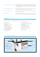
GENERAL SPECIFICATIONS Nominal Voltage Nominal Capacity (Ah) Dimensions Weight Approx (Kg) Layout (V) (20Hr.) (10Hr.) L(mm) W(mm) Height over Terminals (mm) NP4.2-4H 4 4.4 4.20 48 35.5 119 0.56 6 Flat NP10-4 4 10.0 9.25 102 50 98 1.35 1 D NP1-6 6 1.0 0.93 51 42.5 54.5 0.25 5 A NP1.2-6 6 1.2 1.11 97 25 54.5 0.31 1 A NP2.8-6 6 2.8 2.60 134 34 64 0.57 1 A NP3-6 6 3.0 2.78 134 34 64 0.63 1 A NP4-6 6 4.0 3.70 70 47 105.5 0.
Table 2. LAYOUT Table3.
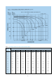
BATTERY CAPACITY SELECTION Figure 2 below may be used to determine the minimum battery size, expressed in Ampere hours of capacity. To determine the required minimum battery capacity, plot the required discharge current, on the horizontal axis, against time. The point where the current and time lines intersect on or below the diagonal Ah curve shows the minimum capacity required for the application.
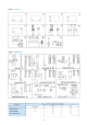
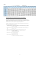
Table 4. DISCHARGE CURRENT AT STIPULATED DISCHARGE RATES Discharge Current 20 Hr. Capacity 0.8 Ah 1.0 1.2 2.1 2.0 2.3 2.8 3.0 4.0 6.0 7.0 8.0 10.0 12.0 17.0 24.0 38.0 65.0 78.0 130.0 0.05C 0.04 A 0.05 0.06 0.105 0.10 0.115 0.14 0.15 0.20 0.30 0.35 0.40 0.50 0.60 0.85 1.20 1.90 3.25 3.90 6.50 0.1C 0.08 A 0.10 0.12 0.21 0.20 0.23 0.28 0.30 0.40 0.60 0.70 0.80 1.00 1.20 1.70 2.40 3.80 6.50 7.8 13.00 0.2C 0.16A 0.20 0.24 0.42 0.40 0.46 0.56 0.60 0.80 1.20 1.40 1.60 2.00 2.40 3.40 4.80 7.60 13.00 15.60 26.
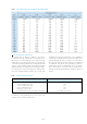
Calculation of battery size required for Constant Power load conditions. Using Table 5 “Watts/Cell/Ah”, map the required load time to the specified end of discharge voltage. The figure obtained is the Constant Power available from each 1Ah of NP type cell. Divide this number into the required wattage load per cell to give the minimum value of capacity required to supply the required load. Example: 5.3kW load requires 30 minutes standby operating from maximum 272V down to end of discharge 204V at 25°C. 1.
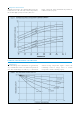
Table 6. DISCHARGE CAPACITY AT VARIOUS DISCHARGE RATES Over Discharge (Deep Discharge) The dotted line in Figure 3 indicates the lowest recommended voltage under load, or cut off voltage, for NP batteries at various discharge rates. In general, lead acid batteries are damaged in terms of capacity and service life if discharged below the recommended cut off voltages. It is generally recognised that all lead calcium alloy grid batteries are subject to over discharge damage.
Temperature Characteristics At higher temperatures, the electrical (Ah) capacity of a battery increases and conversely at lower temperatures, the electrical (Ah) capacity of a battery decreases. Figure 4 shows the effects of different temperatures in relation to battery capacity. STORAGE, SELF DISCHARGE and SHELF LIFE Self Discharge The self discharge rate of NP batteries is approximately 3% per month when stored at an ambient temperature of 20°C.
Shelf Life In general, when lead acid batteries of any type are stored for extended periods of time, lead sulphate is formed on the negative plates of the batteries. This phenomenon is referred to as “sulphation”. Since the lead sulphate acts as an insulator, it has a direct detrimental effect on charge acceptance. The more advanced the sulphation, the lower the charge acceptance. Brief excursions i.e.
Figure 6 shows extrapolated Service Life condition for NP batteries at different ambient temperatures. As can be seen from figure 6 higher ambient temperatures will reduce service life.
AVAILABLE CAPACITY, MEASURED BY OPEN CIRCUIT VOLTAGE The approximate depth of discharge, or remaining capacity, in a Yuasa NP battery can be empirically determined by referring to Figure 7. IMPEDANCE The internal resistance (impedance) of a battery is lowest when the battery is in a fully charged state. The internal resistance increases gradually during discharge, Figure 8 shows the internal resistance of an NP6-12 battery measured through a 1,000 Hz AC bridge.
Impedance testing can be performed using the Yuasa YPI-2 Impedance/comparator test meter, this form of testing is non-intrusive and can be performed online with the battery still connected within its system. (Note: The YPI-2 meter can not be used where a high AC ripple content exists.) By using this test method deterioration can be detected without removing the battery from its standby mode.
– 14 –
– 15 –
– 16 –
Constant Current Charging This charging method is not often utilised for valve regulated lead acid batteries, but is an effective method for charging a number of series connected batteries at the same time, and/or as an equalising charge to correct variances in capacity between batteries in a series group. Extreme care is required when charging NP batteries with a constant current.
Taper Current Charging This method of charging is not recommended due to the constant current characteristics of taper charging being somewhat harsh on valve regulated lead acid batteries. This particular charging regime can often shorten battery service life. However, because of the simplicity of the circuit and subsequent low cost, taper current charging is often used to charge a number of series connected batteries that are subject to cyclic use.
Two Stage Constant Voltage Charging Two stage constant voltage charging is a recommended method for charging valve regulated lead acid batteries in a short period of time and then maintaining them in a fully charged float or standby condition. Figure 20 illustrates the characteristics of a two stage constant voltage charger. The characteristics shown in Fig.20 are those of a constant voltage, current limited charger.
YUASA C.V.C.C. CONSTANT VOLTAGE, CONSTANT CURRENT CHARGE MODULE The Yuasa C.V.C.C. is a fully regulated automatic charging module designed for NP batteries. There are two 6 volt versions available; one for standby applications and the other for cyclic applications. Also there are two 12 volt versions available, again one for standby applications and the other for cyclic applications. When interfaced with the appropriate AC or DC power supply, the Yuasa C.V.C.C.
Solar Powered Chargers A battery is an indispensable component of any solar powered system designed for demand energy use. Since solar cells have inherent constant voltage characteristics, NP batteries can be charged directly from the solar array using a simple diode regulated circuit as shown in Figure 24.
Charging Voltage The charging voltage should be chosen according to the type of service in which the battery will be used. Generally, the following voltages are used: In a constant voltage charging system, a large amount of current will flow during the initial stage of charging but will decrease as the charging progresses. When charging at 2.275 volts per cell, the current at the final stage of charging will drop typically to a value of between 0.0005C Amps and 0.004C Amps.
Initial Charge Current Limit A discharged battery will accept a high charging current at the initial stage of charging. High charging current can cause abnormal internal heating which may damage the battery. Therefore, when applying a suitable voltage to recharge a battery that is being used in a recycling application it is necessary to limit the charging current to a value of 0.25C Amps.
Top Charging Since any battery loses capacity through self discharge, it is recommended that, prior to putting the battery into service, a process called “top charging” be applied to any battery which has been stored for a long period of time. Battery Age Excluding conditions in which storage temperatures have been abnormally high, top charging is recommended within the following parameters: Top Charging Recommendations Within 6 months after manufacture 4 to 6 hours at constant current of 0.
Temperature Compensation As the temperature rises, electrochemical activity in a battery increases and conversely decreases as temperature falls. Therefore, as the temperature rises, the charging voltage should be reduced to prevent overcharge and increased, as the temperature falls, to avoid undercharge. In general, in order to attain optimum service life, the use of a temperature compensated charger is recommended.
Charging Efficiency The charging efficiency ( ) of a battery is expressed by the following formula: (Ah) Ampere hours Discharged = (Ah) Ampere hours Charged The charging efficiency varies depending upon the state of charge of the battery, temperatures and charging rates. Figure 30 illustrates the concept of the state of charge and charging efficiency. As shown in Figure 31, Yuasa NP batteries exhibit very high charging efficiency, even at low charging rates, unlike some nickel cadmium batteries.
The relationship between the number of cycles which can be expected and the depth of discharge is readily apparent. If an extended cycle life is required then it is common practice to select a battery with a larger capacity than the one that is required to carry the load. Thus, at the specified discharge rate over the specified time, the depth of discharge will be shallower and cyclic service life will be longer.
DESIGN/APPLICATION TIPS TO ENSURE MAXIMUM SERVICE lengths of wires, cables or busbars that have the same loop line resistance as each other. This makes sure that each parallel bank of batteries presents the same impedance to the load as any other of the parallel banks thereby ensuring correct equalisation of the source to allow for maximum energy transfer to the load.
GLOSSARY 1. Ampere (A) ................... The unit for measuring the flow of electric current. 2. Ampere hour (Ah) ......... The current in (A amperes) multiplied by time in (h hours). Used to indicate the capacity of a battery. 3. Capacity (C)................... Ampere hours that can be discharged from a battery. 4. Cell................................. The minimum unit of which a battery is composed, consisting of positive and negative plates, separators, electrolyte, etc.
INDEX Abnormal, 23 Abnormally, 8,24 ABS, 28 Absorbed, 29 Absorbent, 28 Accelerated, 27 Accept, 8, 23 Acceptance, 2, 10, 23 Accepted, 24 Accidental, 28 Accuracy, 23 Accurately, 23 Acid, 1, 4, 5, 8, 10, 13, 17, 18, 19, 29 Activity, 25 Adequate, 21, 28 Adhesive, 28 Adjusted, 23 Adjusting, 23 Adjustment, 23 Adjustments, 23 Adverse, 10 Advisable, 28 Advised, 21, 28 Age, 24 Ages, 28 Air, 1, 28 Alarm, 2, 28 Allow, 28 Alloy, 8 Ambient, 2, 5, 9, 10, 11, 22, 25, 27, 28 Ampere, 5, 29 Amperes, 29 Ampere hours, 5, 22, 2
Enclosures, 21 End, 5, 7, 27, 28 Energy, 1, 21, 22, 24, 28, 29 Environmental, 21 Equalisation, 28 Equalising, 17 Exceeds, 1, 5, 21, 28 Excellent, 2 Excursions, 10 Expectancy, 29 Expected, 1, 21, 27, 29 Eye, 28 Fall, 5, 23 Falls, 25 False, 24 Fastened, 28 Faston, 4 Fibre, 1 Final, 5, 7, 8, 22, 29 Fire, 2, 28 Float, 1, 5, 7, 19, 22, 23, 24, 25, 27, 28, 29 Floating, 11 Gas, 1, 29 Gases, 27, 28 Gels, 1 Generate, 28 Generated, 1, 27, 29 Gloves, 28 Gradient, 28 Gradients, 28 Grid, 8 Grids, 1 Handling, 28 Harsh, 1
Regulated, 1, 4, 5, 13, 17, 18, 19, 20, 21, 22, 29 Regulation, 23 Regulations, 1 Reseal, 1 Resin, 28 Resistance, 8, 12, 13, 24, 28, 29 Resistive, 21 Rubber, 28 Rupture, 28 Safe, 1, 20, 28 Safest, 1 Safety, 28 Self, 2, 9, 29 Self Discharge, 2, 9, 24, 29 Separator, 1 Separators, 29 Set, 19, 23, 25 Setting, 28 Severe, 8, 17 Shelf, 2, 9, 10, 29 Shock, 28 Short, 19, 20, 23, 25 Shorten, 18 Silica, 1 Skin, 28 Soaked, 28 Solar, 2, 21 Soldering, 28 Solvents, 28 Sparks, 28 Stage, 13, 19, 22, 23, 24, 29 Stages, 24 Sta
NOTES Further technical information available on request: • • • • • • • • • • • • • • • • • • • • • • • • • Transportation of Yuasa Batteries by Air, Sea or Road Effect of High Temperature on Battery Float Life Gas Production in Valve Regulated Lead Acid (V.R.L.A.) Batteries Safe Handling of product (C.O.S.H.H.) NP Batteries/BS6290 Part 4 Shelf Life, Self Discharge and Top Charging Pre-Installation Battery Checks Recovery of Sulphated Batteries Effects of Altitude on Valve Regulated Lead Acid (V.R.L.A.