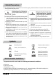
Safety Precautions ▣ The following precautions and directions are measures against possible accidents and injuries. Please read them thoroughly before using this product. Warning Neglecting the following may cause serious injury or death. ▶ Opening the cover of the product while the power cord is plugged into the Current/Voltage Sensor (CVS) may cause electrocution of the user or critical damage to the product. ▶ Handling the power cord with wet hands may cause electrocution.
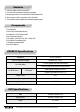
Features 1. Real time display of power consumption. 2. Four sensors for temperature monitoring and display. 3. Monitoring and control of one PWM fan and three standard fans. 4. Alarm system to notify non-operation of any of the fans. 5. Fan’s operation status indicated with animated propeller images. Components 1. One ZM-MFC2 2. One CVS (Current/Voltage Sensor) 3. One Bracket / CVS Extension Cable 4. Four Temperature Sensors 5. Fan Cables - 3-Pin 2EA, 4-Pin 1EA, Y-Cable 1EA 6.
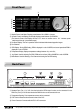
Front Panel Graphic Power Load Meter: Displays power between 30 to 800W in 4 stages. Numeric Power Load Display: Numerically displays power between 30 and 800W. (The Numeric Power Load Display will read“LLL”when an overflow occurs.“LLL”indicates power loads beyond the unit’s measurable range.) Fan Status Display: The Fan’s operation status is indicated with animated propeller images.
Installation 1. Turn the computer’s power OFF and unplug the Main Power Cord before installing ZM-MFC2. 2. Install the ZM-MFC2 into a 5.25" ODD bay as shown in the diagram. 3. Fix it in place with the use of Bolts. 4. Connect the Power Cable and Fan Cables to ZM-MFC2. 5. Connect the Temperature Sensor’s plug to ZM-MFC2, and attach the sensors to desired locations. 6. Install the Bracket in the Enclosure, and connect the CVS Extension Cable to ZM-MFC2. 7. Connect the CVS’s CVS Cable to the Bracket. 8.
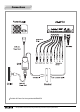
Connections The Main AC Power Cord is not provided with ZM-MFC2. ※ The specifications of product may change without any prior notice to improve performance.
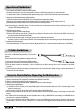
Operational Guidelines Four channels of ZM-MFC2 detect fan RPM signals. The Alarm will activate if a fan is not connected or if there is no RPM input signal for any of the channels. To deactivate the Alarm, the Stand-By Mode (default setting: ON) of each unused channel must be deactivated. 1. Selecting a Channel/Deactivating Stand-By Mode (1) Select a channel with the Mode Button (The selected channel will begin to flicker). (2) Press the Jog Wheel to deactivate the selected channel’s Stand-By Mode.
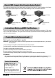
Zalman’s CNPS (Computer Noise Prevention System) Products For a stable and noiseless system of the highest quality, use Zalman’s Ultra Quiet CPU Coolers, Ultra Quiet VGA Coolers, Ultra Quiet Power Supplies, Heatpipe HDD Cooler, Fanless Northbridge Coolers, and Noiseless Case Fans.