
User manual

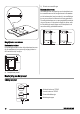
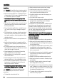
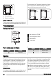

min 20 mm
(max 150 mm)
30 mm
60 mm
b
a
a) Removable panel
b) Space for connections
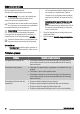
Kitchen unit with oven
The hob recess dimensions must obey the indication and
the kitchen unit must be equipped with vents to let a con-
tinuous supply of air. The electrical connection of the hob
and the oven must be installed separately for safety rea-
sons and to let easy remove oven from the unit.
50 cm
2
360 cm
2
180 cm
2
120 cm
2
Product description
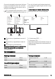
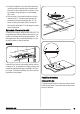
Cooking surface layout
1
2
3
4
180
mm
145
mm
1
Rear cooking zone 1700 W
2
Front cooking zone 1200 W
3
Power indicator
4
Control knobs
Electric cooking zones control knobs
Symbol Function
0 off position
Symbol Function
1 minimum heat
6 maximum heat
Operation
To switch on and increase the heat setting turn the knob
counterclockwise. To decrease the heat setting turn the
knob clockwise. To switch off turn the knob to the 0.
Power indicator is activated when either of the zones are
turned on, and will stay on until the cooking zones are
switched off.
Before first use
Put cookware containing water on each cooking zone, set
the maximum position and operate the appliance for 10
min. This is to burn off the residue in the appliance. After
that, operate the appliance at minimum position for 20
min. During this period, an odour and smoke can occur.
This is normal. Make sure that the airflow is sufficient.
When a cooking zone operates, it hums for a short
time. This is typical of all ceramic glass cooking
zones and does not show that the appliance operates in-
correctly.
20
www.zanussi.com