ELECTRONIC • OLEODYNAMIC • INDUSTRIAL EQUIPMENTS CONSTRUCTION Via Parma, 59 – 42028 – POVIGLIO (RE) – ITALY Tel +39 0522 960050 (r.a.) – Fax +39 0522 960259 e-mail: zapi@zapispa.it – web: www.zapispa.
Copyright © 1975-2006 Zapi S.p.A. All rights reserved The contents of this publication is a ZAPI S.p.A. property; all related authorizations are covered by Copyright. Any partial or total reproduction is prohibited. Under no circumstances will Zapi S.p.A. be held responsible to third parties for damage caused by the improper use of the present publication and of the device/devices described in it. Zapi spa reserves the right to make changes or improvements to its products at any time and without notice.
Contents 1 2 3 4 5 6 INTRODUCTION ...................................................................................................................6 SPECIFICATION ...................................................................................................................7 2.1 Technical specifications - "Dualac2" ...........................................................................7 2.1.1 Block diagram ........................................................................................
6.4.3 "Dualac2&hp" ............................................................................................. 34 6.4.4 "Dualac2&hp Power" .................................................................................. 36 7 DRAWINGS......................................................................................................................... 38 7.1 Mechanical drawing.................................................................................................. 38 7.1.
APPROVAL SIGNS COMPANY FUNCTION INITIALS GRAPHIC AND LAYOUT FF PROJECT MANAGER FG TECHNICAL ELECTRONIC MANAGER VISA PP SALES MANAGER VISA PN SIGN Publication N°: AE9ZP0BD Edition: December 2006 AE9ZP0BD - DUALAC2/&HP/POWER - User Manual Page - 5/89
1 INTRODUCTION Within the ZAPIMOS family, the DUALAC2 inverter is the model suitable for control of pairs of 3.0kW to 7.0kW motors. The DUALAC2&HP can also control a DC-Series pump motor, up to 15kW. These controllers have been expressly designed for battery powered applications, traction and hydraulic functions. They are fit for electric trucks, utility cars, tractors.
2 SPECIFICATION 2.1 Technical specifications - "Dualac2" Inverter for pairs of AC asynchronous 3-phase motors Regenerative braking functions Can-bus interface Flash memory (256 Kbytes On-Chip Program Memory, each microcontroller) Digital control based upon a microcontroller (one per each motor) Voltage: ...............................................................................24 - 36 - 48 - 72 – 80 V Maximum current (24 V):...................................
2.2 Technical specifications - "Dualac2&hp" Inverter for pairs of AC asynchronous 3-phase motors plus chopper for DC series pump motor. Regenerative braking functions Can-bus interface Flash memory (256 Kbytes On-Chip Program Memory, each microcontroller) Digital control based upon a microcontroller (one per each AC motor) Voltage:............................................................................... 24 - 36 - 48 - 72 – 80 V Maximum current (24 V): ..................................
2.2.2 Chopper block diagram 2.3 Technical specifications - "Dualac2 Power" Inverter for pairs of AC asynchronous 3-phase motors Regenerative braking functions Can-bus interface Flash memory (256 Kbytes On-Chip Program Memory, each microcontroller) Digital control based upon a microcontroller (one per each AC motor) Voltage: ...............................................................................24 - 36 - 48 - 72 – 80 V Maximum current (24 V):...................................
External temperature range: .............................................................-30 °C ÷ 40 °C Maximum inverter temperature (at full power): ............................................... 75 °C 2.4.1 Block diagram See chapters 2.2.1 and 2.2.2.
3 SPECIFICATION FOR THE INPUT DEVICES FILLING UP THE INSTALLATION KIT The DUALAC2 inverter needs some external parts in order to work. The following devices complete the kit for the DUALAC2 installation. 3.1 Microswitches - The microswitches must have a contact resistance lower than 0.1 ohm and a leakage current lower than 100 µA. When full load connected, the voltage between the key switch contacts must be lower than 0.1 V.
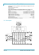
The two graphs show the output voltage from a non-calibrated potentiometer with respect to the mechanical “zero” of the control lever. MI and MA indicate the point where the direction switches close. 0 represents the mechanical zero of the rotation. The Left Hand graph shows the relationship of the motor voltage without signal acquisition being made. The Right Hand Graph shows the same relationship after signal acquisition of the potentiometer. 3.
- - - positive supply: 5 V or 10 V; potentiometer has to be installed in a way that in the "zero" position (straight wheels), poti output voltage is in the middle of the electric range corresponding to a full left-to-right transition of the steered wheels; install the potentiometer in a way that, when truck turns right, poti output voltage increases; use "SET STEER MIN" and "SET STEER MAX" functions to record the extremes (minimum and maximum) of the potentiometer range; see chapter 8.4.
(potentiometer), the axle/wheeltrack ratio is a constant characteristic of the truck that depends on his dimensions. Actually two steering tables are provided: Option #1 = tables for 3 wheels trucks with driving wheels counter-rotation (the internal wheel inverts the direction). Option #2 = tables for 4 wheels trucks without driving wheels counter-rotation (the internal wheel does not inverts the direction).
4 INSTALLATION HINTS In the description of these installation suggestions you will find some boxes of different colours, they mean: 4 U These are informations useful for anyone is working on the installation, or a deeper examination of the content These are Warning boxes, they describe: - operations that can lead to a failure of the electronic device or can be dangerous or harmful for the operator; - items which are important to guarantee system performance and safety 4.
After operation, even with the Key Switch open, the internal capacitors may remain charged for some time. For safe operation, we recommend that the battery is disconnected, and a short circuit is made between Battery Positive and Battery Negative power terminals of the inverter using a Resistor between 10 ohm and 100 ohm. 4.2.1 Positioning and cooling of the controller - - - Install the inverter with the base-plate on a flat metallic surface that is clean and unpainted.
- - U The best cable for can connections is the twisted pair; if it is necessary to increase the immunity of the system to disturbances, a good choice would be to use a cable with a shield connected to the frame of the truck. Sometimes it is sufficient a simple double wire cable or a duplex cable not shielded.
U Correct Layout: R Can Bus Power cables Module 1 Module 2 Module 3 R Note: Module 1 power > Module 2 power > Module 3 power The chain starts from the –BATT post of the controller that works with the highest current, and the others are connected in a decreasing order of power.
- lower costs (less and smaller cables ) - improved reliability (fewer connections) - analysis of problems improved (easy connection with a pc to read the data flowing through the cable). 4.2.4 Wirings: I/O connections - U After crimping the cable, verify that all strands are entrapped in the wire barrel. Verify that all the crimped contacts are completely inserted on the connector cavities.
the logic unit must be set in the correct way by Zapi. 4.2.6 Main contactor and key connection - The connection of the main contactor can be carried out following the drawing in the figure. - The connection of the battery line switches must be carried out following ZAPI instructions.
- - - - External agents: The inverter is protected against dust and the spray of liquid to a degree of protection meeting IP65. Protection against uncontrolled movements: The main contactor will not close if: The Power unit is not functioning. The Logic is not functioning perfectly. The output voltage of the accelerator does not fall below the minimum voltage value stored, with 1 V added. Running microswitch in closed position.
manufacturer holds the responsability to carry out machine validation, based on existing norms (EN12895 for industrial truck; EN50081-2 for other applications). EMC stands for Electromagnetic Compatibility, and it represents the studies and the tests on the electromagnetical energy generated or received by an electrical device.
A) SOURCE OF EMISSIONS: finding the main source of disturb and work on it. B) SHIELDING: enclosing contactor and controller in a shielded box; using shielded cables; C) LAYOUT: a good layout of the cables can minimize the antenna effect; cables running nearby the truck frame or in iron channels connected to truck frames is generally a suggested not expensive solution to reduce the emission level. 2) ELECTROMAGNETIC IMMUNITY. The considerations made for emissions are valid also for immunity.
5 OPERATIONAL FEATURES - - - Speed control. Optimum behaviour an a slope due to the speed feedback: - the motors speed follows the accelerator, starting a regenerative braking if the speed overtakes the speed set-point. - the system can perform an electrical stop on a ramp (the machine is electrically hold on a slope) for a programmable time (see also chapter 8.4). Stable speed in every position of the accelerator. Electronic differential feature with torque balance between external and internal wheel.
safety related inputs hardware. 2) Standby diagnosis in stby that checks: watchdog circuit, phase's voltages, contactor driver, current sensor, can-bus interface. 3) Diagnosis during operation that checks: watchdog circuits, contactor driver, current sensors, can-bus interface. 4) Continuous diagnosis that checks: temperature of the inverter, motor temperature. Diagnosis is provided in two ways.
6 DESCRIPTION OF THE CONNECTORS 6.1 Connectors of the logic - "Dualac2" and "Dualac2 Power" Page - 26/89 A1 CAN_H High level CANBUS. A2 CANT_H CANBUS termination output, 120 ohm internally connected to CAN_H. Connect to CAN_L_OUT to insert the termination. A3 CAN_POS Positive of CAN circuit; to be used in case of optoisolated CANBUS. A4 CAN_L_OUT Low level CANBUS: to be used as repetition for CAN_L line or to be connected to CANT_H to insert termination resistance.
B7 FLASH B8 FLASH C1 PENC_R Positive of right motor encoder power supply (+5 V/+12 V). C2 NENC_R Negative of right motor encoder power supply. C3 KEY Connected to +Batt trough a microswitch and a 10 A fuse in series. C4 CM Common of FW / REV / HB / PB / SEAT / ENABLE / SR / EX. HYDRO / BACKING microswitches. C5 SEAT Seat presence signal; active high. C6 FORWARD Forward direction request signal; active high. C7 REVERSE Reverse direction request signal; active high. C8 ENABLE/BACK.
load > 1 kohm. C34 NTHERM_L Negative of left traction motor temperature sensor. C35 PTHERM_L Left traction motor temperature signal. 6.2 Connectors of the logic - "Dualac2&hp" and "Dualac2&hp Power" Page - 28/89 A1 CAN_H High level CANBUS. A2 CANT_H CANBUS termination output, 120 ohm internally connected to CAN_H. Connect to CAN_L_OUT to insert the termination. A3 CAN_POS Positive of CAN circuit; to be used in case of optoisolated CANBUS.
B6 +12 Positive console power supply. B7 FLASH B8 FLASH C1 PENC_R Positive of right motor encoder power supply (+5 V/+12 V). C2 NENC_R Negative of right motor encoder power supply. C3 KEY Connected to +Batt trough a microswitch and a 10 A fuse in series. C4 CM Common of FW / REV / HB / PB / SEAT / ENABLE / SR / EX. HYDRO / BACKING microswitches. C5 SEAT Seat presence signal; active high. C6 FORWARD Forward direction request signal; active high.
C33 PPOT Traction potentiometer positive, 5/10 V output; use load > 1 kohm. C34 NTHERM_L Negative of left traction motor temperature sensor. C35 PTHERM_L Left traction motor temperature signal. D1 -BATT Negative output. D2 2ND Second hydraulic speed input, active high. D3 1ST First hydraulic speed input, active high. D4 ENABLE Input for proportional lifting enable; active high. D5 CMM Common output of microswitches (+BATT). D6 5TH Fifth hydraulic speed input, active high.
6.3.2 "Dualac2" Controller is a termination module in the canbus net Bridge 2-4 connects one built-in 120 ohm can termination resistance, the second will be connected in another module of the canbus net. 6.3.3 "Dualac2" Controller is a repetition module in the canbus net The canbus built-in termination resistances are not inserted.
6.4 Description of power connections 6.4.1 "Dualac2" View of the power bars: Page - 32/89 -B Negative of the battery. +BT Positive of the battery; if the power fuse is not present, the positive cable coming from LC contact must be connected to this power connection. +BTF Positive of battery before power fuse, must be connected to positive cable coming from LC contact. Um; Vm; Wm Connection bars of the three right motors phases; follow this sequence and the indication on the motor.
6.4.2 "Dualac2 Power" View of the power bars: -B Negative of the battery. +BT Positive of the battery; if the power fuse is not present, the positive cable coming from LC contact must be connected to this power connection. +BTF Positive of battery before power fuse, must be connected to positive cable coming from LC contact. Um; Vm; Wm Connection bars of the three right motors phases; follow this sequence and the indication on the motor.
6.4.3 "Dualac2&hp" View of the power bars: Page - 34/89 -B Negative of the battery. +BT Positive of the battery; if the power fuse is not present, the positive cable coming from LC contact must be connected to this power connection.
+BTF Positive of battery before power fuse, must be connected to positive cable coming from LC contact. Um; Vm; Wm Connection bars of the three right motors phases; follow this sequence and the indication on the motor. Us; Vs; Ws Connection bars of the three left motors phases; follow this sequence and the indication on the motor. -P Output of pump motor chopper.
6.4.4 "Dualac2&hp Power" View of the power bars: Page - 36/89 -B Negative of the battery. +BT Positive of the battery; if the power fuse is not present, the positive cable coming from LC contact must be connected to this power connection.
+BTF Positive of battery before power fuse, must be connected to positive cable coming from LC contact. Um; Vm; Wm Connection bars of the three right motors phases; follow this sequence and the indication on the motor. Us; Vs; Ws Connection bars of the three left motors phases; follow this sequence and the indication on the motor. -P Output of pump motor chopper.
7 DRAWINGS 7.1 Mechanical drawing 7.1.
7.1.
7.1.
7.1.
7.
7.
8 PROGRAMMING & ADJUSTMENTS USING DIGITAL CONSOLE 8.1 Adjustments via Console Adjustment of Parameters and changes to the inverter’s configuration are made using the Digital Console. The Console is connected to the “B” connector of the inverter. 8.2 Description of Console & Connection Digital consoles used to communicate with AC inverter controllers must be fitted with EPROM CK ULTRA, minimum "Release Number 3.02".
8.3 Description of Standard Console Menu 8.3.1 "Dualac2" and "Dualac2 Power" menu configuration 8.3.1.
8.3.1.
8.3.2 "Dualac2&hp" and "Dualac2&hp Power" menu configuration 8.3.2.
8.3.2.
8.4 Function configuration 8.4.1 "Dualac2" and "Dualac2 Power" - Master Using the CONFIG MENU of the programming console, the user can configure the following functions (see "OPERATIONAL FEATURE" chapter for an explanation of "hydraulic steering function"): SUBMENU "SET OPTIONS" 1) HOUR COUNTER - RUNNING: the counter registers travel time only. - KEY ON: the counter registers when the "key" switch is closed.
8) SET TEMPERATURE - DIGITAL: a digital (ON/OFF) motor thermal sensor is connected to C25 (C35) input. - ANALOG: an analog motor thermal sensor is connected to C25 (C35) (the curve can be customized on a customer request). - NONE: no motor thermal sensor switch is connected. 9) STEER TABLE This parameter is used to set the correct steering table. 10) CNC#8 INPUT USE - OPTION #1: input C8 is used as enable input for the traction request, active high (closed switch).
VACC MIN and VACC MAX are values programmable by the "Program Vacc" function. 13) ADJUSTMENT#1 BDI It adjusts the upper level of the battery discharge table. 14) ADJUSTMENT#2 BDI It adjusts the lower level of the battery discharge table. 15) MAIN CONT. VOLTAGE This parameters adjusts the Line contactor coil voltage (PWM output C26). 16) AUX OUTPUT VOLTAGE This parameters adjusts the Electric brake coil voltage (PWM output C28).
- OPTION #3: Equal to OPTION#2 but the truck definitively stops after 380 hours. 8.4.2 "Dualac2" and "Dualac2 Power" - Slave Using the config menu of the programming console, the user can configure the following functions. SUBMENU "SET OPTIONS" 1) CNC#8 INPUT USE - OPTION #1: input C8 is used as enable input for the traction request, active high (closed switch). - OPTION #2: input C8 activates backing function, active high (closed switch). - NONE: input C8 isn’t used.
ENTER). 5) AUX OUTPUT VOLTAGE This parameter adjusts the voltage of the auxiliary output coil (hydraulic steering contactor coil), PWM output C31. 6) THROTTLE 0 ZONE It establishes a deadband in the lifting accelerator input curve (see also curve below). 7) THROTTLE X POINT This parameter changes the characteristic of the lifting accelerator input curve. 8) THROTTLE Y POINT This parameter changes the characteristic of the lifting accelerator input curve.
Flow chart showing how to make changes to OPTIONS Menu. DUALAC2 ZAPI V0.0 48V 350A 00000 1) Opening Zapi Menu. 2) Press Top Left & Right Buttons to enter SET Menu. 3) The Display will show: SET MODEL. % ' % ' ' ' CONFIG MENU SET MODEL 4) Press ROLL UP or ROLL DOWN button until SET MODEL Menu appears. 5) SET OPTIONS appears on the display. % ' ' ' ' ' CONFIG MENU SET OPTIONS ' % ' ' ' ' 6) Press ENTER to go into the SET MODEL Menu. 7) The display will shows the first OPTION.
Flow chart showing how to make changes to ADJUSTMENTS Menu. 1) Opening Zapi Menu. 2) Press Top Left & Right Buttons to enter CONFIG Menu. 3) The display will show: SET MODEL. 4) Press ROLL UP or ROLL DOWN button until ADJUSTMENTS Menu appears. 5) ADJUSTMENTS appears on the display. 6) Press ENTER to go into the ADJUSTMENTS Menu. 7) The display will shows SET POT BRK MIN. 8) Press ROLL UP or ROLL DOWN button until the desired parameter is reached. 9) The desired parameter appears.
Flow chart showing how to use the SET BATTERY TYPE adjustment. DUALAC2 ZAPI V0.0 48V 350A 00000 1) Opening Zapi Menu. 2) Press Top Left & Right Buttons to enter CONFIG Menu. 3) The Display will show: SET MODEL. % ' % ' ' ' CONFIG MENU SET MODEL 4) Press ROLL UP button until ADJUSTMENTS Menu appears. % ' ' ' ' ' 5) ADJUSTMENTS appears on the display. CONFIG MENU ADJUSTMENTS 6) Press ENTER to go into the ADJUSTMENTS Menu. ' % ' ' ' ' 7) The display will show: SET BATTERY TYPE.
Flow chart showing how to carry out ADJUSTMENT BATTERY operation by console. 1) Opening Zapi Menu. DUALAC2 ZAPI V0.0 48V 350A 00000 2) Press Top Left & Right Buttons to enter CONFIG Menu. 3) The Display will show: SET MODEL. % ' % ' ' ' CONFIG MENU SET MODEL 4) Press ROLL UP button until ADJUSTMENTS Menu appears. 5) ADJUSTMENTS appears on the display. % ' ' ' ' ' CONFIG MENU ADJUSTMENTS 6) Press ENTER to go into the ADJUSTMENTS Menu. 7) The display will show the first OPTION.
8.5 Parameter regulation 8.5.1 "Dualac2" - Master The following parameters can be modified: 1) ACCELER. DELAY It determines the acceleration ramp. 2) RELEASE BRAKING It controls the deceleration ramp when the travel request is released. 3) INVERSION BRAKING It controls the deceleration ramp when the direction switch is inverted during travel. 4) PEDAL BRAKING It determines the deceleration ramp when the travel request is released and the brake pedal switch is closed.
17) STOP SMOOTH It sets the level of frequency where the smooth effect on the acceleration ramp ends. standard acceleration ramp f Stop Smooth 0.4 1.0 2.0 3.5 t 0.4, 1.0, 2.0, 3.5 are some possible values of the “Acc. Smooth” and “Inv. Smooth” parameters (see the table below). 18) AUXILIARY TIME It determines the time that the truck is hold on the ramp if the "stop on ramp" option is ON.
The following table shows the different values at which the parameters can be set. PARAMETER PROGRAMMED LEVEL UNIT 0 1 2 3 4 5 6 7 8 9 ACCELERATION DELAY (*) Sec. 1.0 1.5 2.0 2.5 3.0 3.5 4.0 4.5 5.0 5.5 RELEASE BRAKING (**) Sec. 5.5 5.0 4.5 4.0 3.5 3.0 2.5 2.0 1.5 1.0 INVERSION BRAKING (**) Sec. 5.5 5.0 4.5 4.0 3.5 3.0 2.5 2.0 1.5 1.0 PEDAL BRAKING (**) Sec. 4.0 3.5 3.0 2.5 2.0 1.5 1.2 1.0 0.7 0.5 SPEED LIMIT BRAKING (**) Sec. 8.9 8.3 7.7 7.
3) PU. ACCELER. DELAY Acceleration ramp of pump motor. 4) PU. DECELER. DELAY Deceleration ramp of pump motor. 5) CREEP SPEED It determines the minimum lifting speed (per cent of voltage applied to the motor) with a potentiometer control, when the potentiometer is at the minimum of the programmed range. 6) COMPENSATION This parameter sets the voltage compensation (DV) applied to the motor when the proportional lifting function is active.
15) 16) 17) 18) 19) Page - 62/89 when the 4th speed request is active. The value of DV applied to the motor is a function of the motor current. Aim of this function is to reduce, as for as possible, the speed change when the motor is loaded. Increasing the parameter, the DV is increased. 5TH SPEED FINE This parameter sets the voltage compensation (DV) applied to the motor when the 5th speed request is active. The value of DV applied to the motor is a function of the motor current.
The following table shows all the values of parameters. PARAMETER PROGRAMMED LEVEL UNIT 0 1 2 3 4 5 6 7 8 9 SPEED LIMIT % 0 - 100 PUMP IMAX %IMAX 50 55 61 66 72 77 83 88 94 100 PUMP ACCELER DELAY (*) Sec. 0.2 0.4 0.6 0.8 1 1.5 2 2.5 3 3.5 PUMP DECELER DELAY (**) Sec. 0.2 0.4 0.6 0.8 1 1.5 2 2.5 3 3.5 CREEP SPEED % 0 - 100 COMPENSATION % 0 - 100 1ST SPEED FINE % 0 - 100 1ST SPEED COMP. % 0 - 100 2ND SPEED FINE % 0 - 100 2ND SPEED COMP.
After changing a parameter, press ENTER to confirm data when requested by the message on the console. Parameters modified and optimized on one unit can be stored by the Zapi Pc-console (SAVE) and then downloaded (RESTORE) to another controller, thus allowing fast and standardized settings (see Pc-console manual for details). Flow Chart showing how to make Parameter changes using Digital Console fitted with Eprom CK ULTRA. DUALAC2 ZAPI V0.0 48V 350A 00000 1) Opening Zapi Display.
8.6 Programming console functions 8.6.1 "Dualac2" and "Dualac2 Power" - - - Functional configuration (see 8.4) Parameter programming (see 8.
- - current rms (A) current rms (A) temperature (°C) temperature (°C) temperature #1(°C) voltage booster (%) temperature #2(°C) battery voltage (V) accelerator (V) seat switch (ON/OFF) steer angle (°) forward switch (ON/OFF) int.
9) Set the FREQUENCY CREEP level starting from level 0.3 Hz. The machine should just move when the accelerator microswitch is closed. Increase the Level accordingly. 10) Set the Speed Reductions as required. Make adjustments to “CUTBACK SPEED 1” Check the performance with the accelerator pedal totally depressed. If the machine is a forklift, check the performance with and without load. 11) RELEASE BRAKING. Operate the machine at full speed. Release the accelerator pedal.
steering function request is switched off). 12) Set “SET TEMPERATURE”, setting the motor thermal sensor type used. 8.9 Tester: description of the function The most important input or output signals can be measured in real time using the TESTER function of the console. The Console acts as a multimeter able to read voltage, current and temperature. In the following chapter a list of relative measurements for different configurations. 8.9.
15) SEAT SWITCH The level of the Seat Microswitch digital input. - ON / +VB = input active, switch closed. - OFF / GND = input non active, switch open. 16) BACKING SWITCH The level of the Backing Microswitch. - ON / +VB = input active, switch closed. - OFF / GND = input non active, switch open. 17) CUTBACK SWITCH The level of the Speed Reduction Microswitch. - ON / GND = input active, switch opened. - OFF / +VB = input non active, switch closed. 18) BRAKE SWITCH The level of the Pedal Brake Microswitch.
7) VOLTAGE BOOSTER This is the booster of the voltage supplied to the motor in load condition; it is expressed in a percentage of the full voltage. 8) BATTERY VOLTAGE Level of battery voltage measured at the input of the key switch. 9) SEAT SWITCH The level of the Seat Microswitch digital input. - ON / +VB = input active, switch closed. - OFF / GND = input non active, switch opened. 10) FORWARD SWITCH The level of the Forward direction digital input FW. - ON / +VB = input active, switch closed.
11) BACKWARD SWITCH The level of the Reverse direction digital input BW. ON / +VB = input active, switch closed. OFF / GND = input non active, switch open. 12) ENABLE SWITCH The level of the Enable digital input: ON / +VB = input active, switch closed. OFF / GND = input non active, switch open. 13) LIFTING CONTROL Voltage of the lifting potentiometer (CPOT LIFT). 14) LIFTING SWITCH Status of the lifting switch. ON / +VB = input active, switch closed. OFF / GND = input non active, switch open.
Flow Chart showing how to use the TESTER function of the Digital Console. DUALAC2 ZAPI V0.0 48V 350A 00000 1) Opening Zapi Display. 2) Press ENTER to go into the General menu. ' % ' ' ' ' MAIN MENU PARAMETER CHANGE 3) The Display will show: 4) Press ROLL UP or ROLL DOWN button until TESTER MENU appear on the display. % ' ' % ' ' MAIN MENU TESTER 5) The Display shows: 6) Press ENTER to go into the TESTER function. ' % ' ' ' ' 7) The first variable to be tested is shown on the Display.
9 OTHER FUNCTIONS 9.1 Save and Restore function SAVE function allows to transfer controller parameters to the Pc console memory. With this function, a copy of the controller set of parameters can be retained in a Pc and downloaded to another controller (see RESTORE). RESTORE function allows to download controller parameters from the Pc console memory to the controller Eeprom. Thus a copy of the parameters stored in a Pc can be downloaded in a controller avoiding the parameter setting operation.
10) When you have finished looking at the Alarms, press OUT to exit the ALARMS menu. ' ' ' ' % ' 11) The Display will ask “CLEAR LOGBOOK?”. CLEAR LOGBOOK? YES=ENTER NO=OUT 12) Press ENTER for yes, or OUT for NO. ' % ' ' ' ' 13) Press OUT to return to the Opening Zapi Display. ' ' ' ' % ' ' ' ' ' % ' 9.3 Description of Console Program Vacc function This function looks for and remembers the minimum and maximum potentiometer wiper voltage over the full mechanical range of the pedal.
10) Slowly depress the accelerator pedal (or tiller butterfly) to its maximum value. The new minimum and maximum voltages will be displayed on the Console plus an arrow indicating the direction. 11) Select the Reverse Direction and repeat Item 10. 12) When finished, press OUT. 13) The Display will ask: “ARE YOU SURE?”. 14) Press ENTER for yes, or OUT for NO. 15) When finished, the Console shows: 16) Press OUT again to return to the Opening Zapi Menu. AE9ZP0BD - DUALAC2/&HP/POWER - User Manual MIN 0.
10 "DUALAC2" AND "DUALAC2&HP" INVERTER DIAGNOSTIC 10.
Co de ALARM STRING Ma ster Slave CONTROLLER STATUS Init Stby DESCRIPTION Condition that has to occur to come out from alarm status -If the alarm is present in Init status, remove the alarm condition -If the alarm has occurred in stby or running mode, it is necessary to remove alarm condition and to activate a traction request -If the alarm is present in Init status, remove the alarm condition -If the alarm has occurred in stby or running mode, it is necessary to remove alarm condition and to activat
Co de ALARM STRING Ma ster CONTROLLER STATUS Slave Init Stby X Motor running X DESCRIPTION Condition that has to occur to come out from alarm status Alarm: -Init: the LC and EB coil driver protection circuit is damaged - Stby or running: short on LC coil or EB coil -If the alarm is present in Init status, remove the alarm cause -If the alarm has occurred in stby or running mode, it is necessary to remove alarm cause and to activate traction request To remove alarm cause within a timeout; if the t
Co de ALARM STRING Ma ster CONTROLLER STATUS Slave Init Stby 246 MASTER KO X X X Motor running X 250 INPUT MISMATCH X X X X 253 AUX OUTPUT KO X X X X 13 EEPROM KO X X X X X 61 HIGH TEMPERATURE X X X X X 65 MOTOR TEMPERATURE X X X X X 66 BATTERY LOW X X X X AE9ZP0BD - DUALAC2/&HP/POWER - User Manual DESCRIPTION Alarm: Slave µC detects a Master µC malfunctioning or a mismatch between inputs status and Master commands (via Canbus) Alarm: Slave µC has detect
Co de ALARM STRING Ma ster CONTROLLER STATUS Slave Init Stby VACC NOT OK X X X 79 INCORRECT START X X X X 80 FORWARD + BACKWARD X X X X 249 THERMIC SENSOR KO X X X X 251 WAITING FOR NODE#4 X X X X 251 WAITING FOR NODE#3 X X X 247 NO CAN MESSAGE #4 X X X 247 NO CAN MESSAGE #3 X X X 244 SLAVE WARNING HANDBRAKE X X X X X 250 Page - 80/89 X X X X X Condition that has to occur to come out from alarm status Motor running 78 X DESCRIPTION Warning:
Co de ALARM STRING Ma ster CONTROLLER STATUS Slave Init 241 DATA ACQUISITION X 248 CHECK UP NEEDED X X Stby X X DESCRIPTION Condition that has to occur to come out from alarm status Warning: Maximum current adjustment procedure is in progress (NOTE: this procedure has to be done only by Zapi test department) Warning: maintenance time is reached To remove Warning cause and to activate traction request Motor running To remove Warning cause 10.
7) CAPACITOR CHARGE Follows the charging capacitor system: When the key is switched ON, the inverter tries to charge the capacitor through a power resistance, and check if the capacitor are charged within a timeout. If they do not charge, an alarm is signalled; the main contactor is not closed. Possible reasons: A) the charging resistance is opened. B) The charging circuit has a failure. C) There is a problem in the power section.
11) 12) 13) 14) 15) 16) 17) 18) A) the "Set steer 0 pos" (straight wheels programming) parameter is wrong (lower than "Set steer min" or higher than "Set steer max"). B) the feedback signal of the steering potentiometer is outside the window defined by "Set steer min" and "Set steer max" parameters. In the first case, repeat the steering potentiometer acquisition. In the second case, check the steering poti and its wiring. Eventually, repeat again the steering potentiometer acquisition.
19) MOTOR TEMPERATURE This warning is signalled if right or left or both motors temperature switches open (digital sensor) or if the analog signals overtakes the cut off level. If it happens when the motor is cold, check the wiring. If all is ok, replace the logic board. 20) BATTERY LOW If the "battery check" option is ON, a battery discharge algorithm is carried out. When the charge level is 20% , this alarm is signalled and the current is reduced to the half of the programmed level.
29) SLAVE WARNING The slave has a warning. Connect to the slave with the hand set console and check the warning. 30) HANDBRAKE This warning occurs when the operator try to travel with the handbrake active. Possible causes: A) handbrake microswitch failure; B) incorrect wiring; C) if the defect persists, replace the logic. 31) DATA ACQUISITION This warning signals that the inverter is in the acquisition of the current gains phase; it ends when the acquisition is done.
Cod e ALARM STRING Ma ster CONTROLLER STATUS Slave X Init Stby X X 242 Ma ster PUMP WARNING 243 PUMP INC. START X X X 244 PUMP VACC NOT OK X X X 245 PUMP TH. SENS.
6) PUMP VACC NOT OK This is a warning in the pump chopper, which inform that accelerator voltage is 1 V grater than the minimum value programmed. 7) PUMP TH. SENS. KO The range of pump chopper temperature sensor is always checked and a warning is signalled if it is out of range. When this warning is signalled, the maximum current of the pump chopper is reduced to half.
11 RECOMMENDED SPARE PARTS FOR INVERTER Part Number Description C16507 Protected 500 A strip Fuse C16505 Protected 355 A strip Fuse C16520 10 A 20 mm Control Circuit Fuse C29523 SW 180 80 V Single Pole Contactor C29522 SW 180 48 V Single Pole Contactor C29508 SW 180 24 V Single Pole Contactor Page - 88/89 C12529 Ampseal Connector 8 pins Female C12532 Ampseal Connector 35 pins Female C12530 Ampseal Connector 14 pins Female C12796 Female pin harness side AE9ZP0BD - DUALAC2/&HP/POWER - U
12 PERIODIC MAINTENANCE TO BE REPEATED AT TIMES INDICATED Check the wear and condition of the Contactors’ moving and fixed contacts. Electrical Contacts should be checked every 3 months. Check the Foot pedal or Tiller microswitch. Using a suitable test meter, confirm that there is no electrical resistance between the contacts by measuring the volt drop between the terminals. Switches should operate with a firm click sound. Microswitches should be checked every 3 months.