
User manual


AE9ZP0BD - DUALAC2/&HP/POWER - User Manual Page - 3/89
Contents
1 INTRODUCTION ...................................................................................................................6
2 SPECIFICATION ...................................................................................................................7
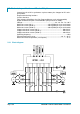
2.1 Technical specifications - "Dualac2"...........................................................................7
2.1.1 Block diagram ...............................................................................................7
2.2 Technical specifications - "Dualac2&hp".....................................................................8
2.2.1 Block diagram ...............................................................................................8
2.2.2 Chopper block diagram.................................................................................9
2.3 Technical specifications - "Dualac2 Power"................................................................9
2.3.1 Block diagram ...............................................................................................9
2.4 Technical specifications - "Dualac2&hp Power" .........................................................9
2.4.1 Block diagram .............................................................................................10
3 SPECIFICATION FOR THE INPUT DEVICES FILLING UP THE INSTALLATION KIT.....11
3.1 Microswitches ...........................................................................................................11
3.2 Accelerator unit.........................................................................................................11
3.3 Other analog control unit ..........................................................................................12
3.4 Speed feedback........................................................................................................12
3.5 Steering angle transducer.........................................................................................12
4 INSTALLATION HINTS.......................................................................................................15
4.1 Material overview......................................................................................................15
4.1.1 Connection cables ......................................................................................15
4.1.2 Contactors...................................................................................................15
4.1.3 Fuses ..........................................................................................................15
4.2 Installation of the hardware.......................................................................................15
4.2.1 Positioning and cooling of the controller .....................................................16
4.2.2 Wirings: power cables.................................................................................16
4.2.3 Wirings: CAN connections and possible interferences ...............................16
4.2.4 Wirings: I/O connections.............................................................................19
4.2.5 Encoder installation.....................................................................................19
4.2.6 Main contactor and key connection ............................................................20
4.2.7 Insulation of truck frame..............................................................................20
4.3 Protection and safety features..................................................................................20
4.3.1 Protection features......................................................................................20
4.3.2 Safety Features...........................................................................................21
4.4 EMC..........................................................................................................................21
4.5 Various suggestions .................................................................................................23
5 OPERATIONAL FEATURES ..............................................................................................24
5.1 Diagnosis..................................................................................................................24
6 DESCRIPTION OF THE CONNECTORS............................................................................26
6.1 Connectors of the logic - "Dualac2" and "Dualac2 Power" ......................................26
6.2 Connectors of the logic - "Dualac2&hp" and "Dualac2&hp Power" .........................28
6.3 CANBUS connector description................................................................................30
6.3.1 "Dualac2" Controller in stand-alone configuration ......................................30
6.3.2 "Dualac2" Controller is a termination module in the canbus net.................31
6.3.3 "Dualac2" Controller is a repetition module in the canbus net....................31
6.4 Description of power connections.............................................................................32
6.4.1 "Dualac2" ....................................................................................................32
6.4.2 "Dualac2 Power".........................................................................................33