COSTRUZIONE APPARECCHIATURE ELETTRONICHE - OLEODINAMICHE - INDUSTRIALI 42028 - POVIGLIO - (R.E.) - Via Parma, 59 - ITALIA Tel. +39 0522 960050 (r.a.) - Fax +39 0522 960259 - E-mail: infozapi@tin.
INDEX 1 2 3 4 Page Introduction .................................................................................................... 3 Specification .................................................................................................. 3 2.1 Technical specifications ........................................................................ 3 2.2 Control unit ............................................................................................ 4 2.2.a Microswitches .......................
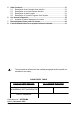
5 6 7 8 Other functions ............................................................................................ 51 5.1 Description of the Console Save function ............................................ 51 5.2 Description of Console Restore function. ............................................ 52 5.3 Description of Alarms menu ................................................................ 53 5.4 Description of Console Program Vacc function ...................................
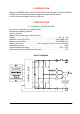
1 INTRODUCTION Within the ZAPIMOS family, the AC1 inverter is the model suitable for control of 700W to 2.5kW motors. It has been expressly designed for battery electric traction. It is fit for electric transpallet, golf cars, utility cars. 2 SPECIFICATION 2.1 TECHNICAL SPECIFICATIONS Inverter for AC asyncronous 3-phase motors Regenerative braking functions Can-bus interface Digital control based upon a microcontroller Voltage: ...............................................................................
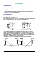
2.2 CONTROL UNIT 2.2.a Microswitches - The microswitches must have a contact resistance lower than 0.1Ω and a leakage current lower than 100µA. - When full load connected, the voltage between the key switch contacts must be lower than 0.1V. - The microswitches send a voltage signal to the microprocessor when a function request (for ex.: running request) is made. 2.2.b Accelerator unit The accelerator unit can consist of a potentiometer or an Hall effect device. It should be in a 3-wire configuration.
The two graphs show the output voltage from a non-calibrated potentiometer with respect to the mechanical zero of the control lever. MI and MA indicate the point where the direction switches close. 0 represents the mechanical zero of the rotation. The Left Hand graph shows the relationship of the motor voltage without signal aquisition being made. The Right Hand Graph shows the same relationship after signal aquisition of the potentiometer. 2.2.
2.3 PROTECTION FEATURES - Battery polarity inversion: It is necessary to fit a MAIN CONTACTOR to protect the inverter against reverse battery polarity and for safety reasons. - Connection Errors: All inputs are protected against connection errors. - Thermal protection If the chopper temperature exceeds 75°C, the maximum current is reduced in proportion to the thermal increase. The temperature can never exceeds 100°C.
2.4 OPERATIONAL FEATURES - Speed control. - Optimum behaviour an a slope due to the speed feedback: - the motor speed follows the accelerator, starting a regenerative braking if the speed overtakes the speed set-point. - the system can perform an electrical stop on a ramp (the machine is electrically hold on a slope) for a programmable time (see also chapter 4) - Stable speed in every position of the accelerator. - Regenerative release braking based upon deceleration ramps.
2.5 DIAGNOSIS The microprocessor continually monitors the inverter and carries out a diagnostic procedure on the main functions. The diagnosis is made in 4 points 1) Diagnosis on key switch closing that checks: watchdog circuit, current sensor, capacitor charging, phase's voltages, contactor drives, can-bus interface, if the switch sequence for operation is correct and if the output of accelerator unit is correct.
2.8 SUSCEPTIBILITY AND ELECTROMAGNETIC EMISSION Electromagnetic susceptibility and emission are strongly influenced by the installation. Special attention must be given to the lengths and the paths of the electric connections and the shields. This situation is beyond ZAPI's control. Therefore ZAPI declines any responsibility for noncompliance if correct testing is not made (the irradiated emission directive is EN50081-2). 2.
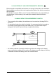
3 INSTALLATION Install the chopper with the base-plate on a flat metallic surface that is clean and unpainted. Apply a light layer of thermo-conductive grease between the two surfaces to permit better heat dissipation. Ensure that the wiring of the cable terminals and connectors is carried out correctly. Fit transient suppression devices to the horn, solenoid valves, and contactors not connected to the chopper such as those for activating the pump motor or steering motor. 3.
3.4 DESCRIPTION OF CONNECTORS - STANDARD VERSION A1 NLC Negative of main contactor coil. A2 PLC , PEB Positive of main contactor coil and electromechanical brake coil. A3 NBRAKE Output for driving the electromechanical brake coil; drives the load to -Batt. Maximum current : 3A. A4 NPC Negative of pump contactor coil. A5 PPC , PEV Positive of pump contactor coil and lowering electrovalve coil. A6 NEV Negative of the lowering electrovalve coil. A7 CAN-L Low level CAN-BUS voltage I/O.
A15 SR3 Speed reduction 3 input. Active low (switch opened). A16 +12V This output provides a +12V signal for thr MDI PRC, if present; 100mA maximum current. A17 CAN-H High level CAN-BUS voltage I/O. A18 CPOTB Brake potentiometer wiper. A19 ENCODER Incremental ENCODER (see chapter 3.6). A20 ENCODER Incremental ENCODER (see chapter 3.6). B1 KEY Connected to the power supply through a microswitch (KEY) with a 10A fuse in series.
3.5 DESCRIPTION OF CONNECTORS - MDI PRC VERSION A1 NLC Negative of main contactor coil. A2 PLC , PEB Positive of main contactor coil and electromechanical brake coil. A3 NBRAKE Output for driving the electromechanical brake coil; drives the load to -Batt. Maximum current : 3A. A4 NPC Negative of pump contactor coil. A5 PPC , PEV Positive of pump contactor coil the auxiliary output load. A6 NEV Negative of the auxiliary output. A7 CAN-L Low level CAN-BUS voltage I/O. A8 NPOTB -Batt.
A15 LOW AUX. Auxiliary lowering request input, active high. A16 +12V This output provides a +12V signal for thr MDI PRC; 100mA maximum current. A17 CAN-H High level CAN-BUS voltage I/O. A18 CPOTB Proprtional electrovalves potentiometer wiper. A19 ENCODER Incremental ENCODER (see chapter 3.6). A20 ENCODER Incremental ENCODER (see chapter 3.6). B1 KEY Connected to the power supply through a microswitch (KEY) with a 10A fuse in series.
3.6 ENCODER INSTALLATION 1) AC1 card is fit for different types of encoder. To control AC motor with Zapi inverter, it is necessary to install an incremental encoder with 2 phases shifted of 90°. The encoder power supply can be +5 or +12V. It can have different electronic output. A9 +5V/+12V positive of encoder power supply. A10 GND negative of encoder power supply. A19 A phase A of encoder. A20 B phase B of encoder. 2) Connection of encoder with open collector output; +5V power supply.
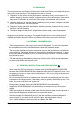
3.7 DESCRIPTION OF POWER CONNECTIONS View of the power bars: -BATT +BATT U; V; W 2=CA $ Negative of the battery. Positive of the battery. Connection bars of the three motor phases; follow this sequence and the indication on the motor.
3.
3.
3.
4 PROGRAMMING & ADJUSTMENTS USING DIGITAL CONSOLE 4.1 ADJUSTMENTS VIA CONSOLE Adjustment of Parameters and changes to the inverters configuration are made using the Digital Console. The Console is connected to the C connector of the inverter. 4.2 DESCRIPTION OF CONSOLE & CONNECTION Digital consoles used to comunicate with AC inverter controllers must be fitted with EPROM CK ULTRA, minimum "Release Number 3.02".
4.3 DESCRIPTION OF STANDARD CONSOLE MENU 4.3.
4.3.
4.4 FUNCTION CONFIGURATION 4.4.a Standard Version SUBMENU "SET OPTIONS" 1 TILLER SWITCH 2 3 4 5 6 7 8 - HANDLE input B3 is managed as a tiller input. - SEAT input B3 is managed as a seat input. SET INPUT #1 - PRESENT: input A13 is managed as a cutback speed input. - OPTION #1: input A13 is managed as an handbrake input. SET INPUT #2 - PRESENT: input A14 is managed as a cutback speed input. - OPTION #1: input A14 is managed as an "Inching Forward" input.
9 STOP ON RAMP - ON: the stop on ramp feature (truck electrically hold on a ramp) is managed for a time established by "auxiliary time" parameter. After this time, the behaviour depends on the "aux output #1" option programmation (see also the following table). - OFF: the stop on ramp feature is not performed. 10 AUX OUTPUT #1 - BRAKE: output A3 drives an electromagnetic brake coil (see also the table below). - HYDRO CONT.
- NONE: 12 Means that there aren't any switch or potentiometer installed on the brake. QUICK INVERSION - NONE The quick inversion function is not managed. - TIMED The quick inversion function is timed. - BELLY The quick inversion function is managed but not timed. 13 AUX VOLTAGE #1 - % 14 this parameter permits to program the supply voltage of the main contactor coil and the electromechanical brake. PERFORMANCE - OPTION #1 Set of parameter which determines a "Low Performance".
7 THROTTLE Y POINT: These parameter change the characteristic of the accelerator input curve. VACC MIN and VACC MAX are values programmable by the "Program Vacc" function. 8 ADJUSTMENT #01: adjust the upper level of the battery discharge table. 9 ADJUSTMENT #02: adjust the lower level of the battery discharge table.
AUX OUTPUT BRAKE BRAKE HYDRO CONT. HYDRO CONT. EXCL. HYDRO EXCL. HYDRO STOP ON RAMP A3 OUTPUT BEHAVIOUR ON A SLOPE ON The truck is electrically hold on a slope; when the time set by "auxiliary time" parameter is elapsed -Drives the coil of a electromagnetic the brake is applied and the 3brake. phase bridge is released. Do not use this combination if the negative brake is not installed.
4.4.b MDI PRC Version SUBMENU "SET OPTIONS" 1 TILLER SWITCH 2 3 4 5 6 - HANDLE input B3 is managed as a tiller input. - SEAT input B3 is managed as a seat input. SET INPUT #1 - PRESENT: input A13 is managed as a cutback speed input. - OPTION #1: input A13 is managed as an handbrake input. SET INPUT #4 - BELLY: input B7 is managed as a belly input. - BRAKE: input B7 is managed as a service brake input. - EX. HYDRO: input B7 is managed as a "Exclusive Hydro" input.
8 AUX OUTPUT #1 - BRAKE: output A3 drives an electromagnetic brake coil (see also the table below). - HYDRO CONT.: the inverter manages an hydraulic steering function when the direction input or brake pedal input are active or a movement of the truck is detected. - EX. HYDRO: output A3 drives an hydraulic steering function when the exclusive hydro input is active. 9 PEDAL BRAKING - ANALOG: Option "Set input #4" programmed "Belly": the mechanical brake pedal has a potentiometer installed.
11 AUX VOLTAGE #1 - % 12 this parameter permits to program the supply voltage of the main contactor coil and the electromechanical brake. PERFORMANCE - OPTION #1 Set of parameter which determines a "Low Performance". - OPTION #2 Set of parameter which determines a "High Performance". 13 VALVE 1 TYPE - OPTION #1 Electrovalve n°1 is an On/Off valve. - OPTION #2 Electrovalve n°1 is a proportional valve. 14 VALVE 2 TYPE - OPTION #1 Electrovalve n°2 is an On/Off valve.
7 THROTTLE Y POINT: These parameter change the characteristic of the accelerator input curve. VACC MIN and VACC MAX are values programmable by the "Program Vacc" function. 8 ADJUSTMENT #01: adjust the upper level of the battery discharge table. 9 ADJUSTMENT #02: adjust the lower level of the battery discharge table.
AUX OUTPUT BRAKE BRAKE STOP ON RAMP A3 OUTPUT BEHAVIOUR ON A SLOPE ON The truck is electrically hold on a slope; when the time set by "auxiliary time" parameter is elapsed -Drives the coil of a electromagnetic the brake is applied and the 3brake. phase bridge is released. Do not use this combination if the negative brake is not installed.
Flow chart showing how to make changes to OPTION Menu. 1) Opening Zapi Menu 2) Press Top Left & Right Buttons to enter SET Menu. 3) The Display will show: SET MODEL 4) Press ROLL UP or ROLL DOWN button until SET MODEL Menu appears. 5) SET OPTIONS appears on the display. 6) Press ENTER to go into the SET MODEL Menu. 7) The display will shows the first OPTION. 8) Press ROLL UP or ROLL DOWN button until desired OPTION appears 9) Desired OPTION appears.
Flow chart showing how to make changes to ADJUSTMENT Menu 1) Opening Zapi Menu 2) Press Top Left & Right Buttons to enter CONFIG Menu. 3) The display will show: SET MODEL 4) Press ROLL UP or ROLL DOWN button until ADJUSTMENTS Menu appears. 5) ADJUSTMENTS appears on the display. 6) Press ENTER to go into the ADJUSTMENTS Menu. 7) The display will shows SET BATTERY TYPE. 8) Press ROLL UP or ROLL DOWN button until the desired parameter is reached. 9) The desired parameter is appears.
Flow chart showing how to use the SET BATTERY TYPE adjustment 1) Opening Zapi Menu 2) Press Top Left & Right Buttons to enter CONFIG Menu. 3) The Display will show: SET MODEL 4) Press ROLL UP button until ADJUSTMENTS. menu appears. 5) ADJUSTMENTS appears on the display. 6) Press ENTER to go into the ADJUSTMENTS Menu. 7) The display will show: SET BATTERY TYPE. 8) Press SET UP to choose nominal value of the battery. 9) New battery value appears. 10) Press OUT. 11) Confirmation request appears.
Flow chart showing how to carry out ADJUSTMENT BATTERY operation by console. 1) Opening Zapi Menu 2) Press Top Left & Right Buttons to enter CONFIG Menu. 3) The Display will show: SET MODEL 4) Press ROLL UP button until ADJUSTMENT Menu appears. 5) ADJUSTMENTS appears on the display. 6) Press ENTER to go into the ADJUSTMENTS Menu. 7) The display will show the first OPTION. 8) Press ROLL UP or ROLL DOWN button until desired OPTION appears 9) ADJUST BATTERY appears.
4.5 PARAMETER REGULATION: STANDARD VERSION The following parameters can be modified: 1 2 ACC DELAY: RELEASE BRAKING: 3 INVERSION BRAKING: 4 PEDAL BRAKING: 5 SPEED LIMIT BRAKING: 6 BRAKE CUTBACK: 7 8 MAX SPEED FORWARD: MAX SPEED BACKWARD: 9 10 11 12 13 CUTBACK SPEED 1: CUTBACK SPEED 2: CUTBACK SPEED 3: H&S CUTBACK: FREQUENCY CREEP: 14 15 16 17 MAXIMUM CURRENT: BACKING SPEED: BACKING TIME: AUXILIARY TIME: determines the acceleration ramp.
The following table shows the different values at which the parameters can be set. PROGRAMMED LEVEL UNIT 0 1 2 3 4 5 6 7 8 9 ACCELERATION DELAY (*) Sec. 2.5 3.0 3.5 4.0 4.5 5.0 5.5 6.0 6.5 7.0 RELEASE BRAKING (**) Sec. 5.5 5.0 4.5 4.0 3.5 3.0 2.5 2.0 1.5 1.0 INVERS BRAKING (**) Sec. 5.5 5.0 4.5 4.0 3.5 3.0 2.5 2.0 1.5 1.0 PEDAL BRAKING (**) Sec. 5.5 5.0 4.5 4.0 3.5 3.0 2.5 2.0 1.5 1.0 SPEED LIMIT BRAKING (**) Sec. 8.9 8.3 7.7 7.1 6.6 6.0 5.
4.6 PARAMETER REGULATION: MDI PRC VERSION The following parameters can be modified: 1 2 ACC DELAY: RELEASE BRAKING: 3 INVERSION BRAKING: 4 PEDAL BRAKING: 5 SPEED LIMIT BRAKING: 6 BRAKE CUTBACK: 7 8 MAX SPEED FORWARD: MAX SPEED BACKWARD: 9 CUTBACK SPEED 1: 10 H&S CUTBACK: 11 FREQUENCY CREEP: 12 MAXIMUM CURRENT: 13 BACKING SPEED: 14 BACKING TIME: 15 AUXILIARY TIME: 16 MIN VALVE 1: 17 MIN VALVE 2: determines the acceleration ramp.
18 MAX VALVE 1: 19 MAX VALVE 2: 20 VALVE 3 VOLTAGE: 21 VALVE 4 VOLTAGE: 22 V1 OPENING RAMP 23 V2 OPENING RAMP 24 V1 CLOSING RAMP 25 V2 CLOSING RAMP 2=CA " this parameter determines the maximum voltage applied on the electrovalve 1 when the position of the potentiometer is at the maximum. If the electrovalve 1 is programmed like a On/Off valve (see the configuration chapter) this parameter determines the voltage applied on the electrovalve coil.
The following table shows the different values at which the parameters can be set. PROGRAMMED LEVEL UNIT 0 1 2 3 4 5 6 7 8 9 ACCELERATION DELAY (*) Sec. 2.5 3.0 3.5 4.0 4.5 5.0 5.5 6.0 6.5 7.0 RELEASE BRAKING (**) Sec. 5.5 5.0 4.5 4.0 3.5 3.0 2.5 2.0 1.5 1.0 INVERS BRAKING (**) Sec. 5.5 5.0 4.5 4.0 3.5 3.0 2.5 2.0 1.5 1.0 PEDAL BRAKING (**) Sec. 5.5 5.0 4.5 4.0 3.5 3.0 2.5 2.0 1.5 1.0 SPEED LIMIT BRAKING (**) Sec. 8.9 8.3 7.7 7.1 6.6 6.0 5.
1) Opening Zapi Display. 2) Press ENTER to go into the General Menu. 3) The Display will show : 4) Press ENTER to go into the Parameter Change facility. 5) The Display will show the first parameter. 6) Press either ROLL UP and ROLL DOWN to display the next parameter. 7) The names of the Parameters appear on the Display. 8) When the desired Parameter appears, the Display will show a Level Number that will be between 0 and 9.
4.7 PROGRAMMING CONSOLE FUNCTIONS - Functional configuration (see 4.1 , 4.2 , 4.3 , 4.4) - Parameter programming (see 4.5 , 4.
4.8 SEQUENCE FOR AC INVERTER TRACTION SETTING When the "Key Switch" is closed, if no alarms or errors are present, the Console Display will be showing the Standard Zapi Opening Display. If the chopper is not configured to your requirements, follow the sequence detailed on Chapter 5.2 . Remember to re-cycle the Key Switch if you make any changes to the choppers configuration. Otherwise follow the sequence detailed below : 1) Select the Options required. See Chapter 4.1 ÷ 4.4.
4.9 TESTER: DESCRIPTION OF THE FUNCTION; STANDARD VERSION The most important input or output signals can be measured in real time using the TESTER function of the console. The Console acts as a multimeter able to read voltage, current and temperature. The following definition listing shows the relative measurements : 1) BATTERY VOLTAGE: level of battery voltage measured at the input to the key switch.
18) SEAT SWITCH: the level of the Seat Microswitch digital entry. ON / +VB = active entry of closed switch. OFF / GND = non active entry of open switch. or: TILLER SWITCH: the level of the Tiller Microswitch digital entry. ("Tiller switch" option set as "Handle"). ON / +VB = active entry of closed switch. OFF / GND = non active entry of open switch. 19) H&S CUTBACK: the level of the Hard&Soft Microswitch digital entry. ON / +VB = active entry of closed switch. OFF / GND = non active entry of open switch.
INCHING FORW: the level of the Inching Microswitch - Forward direction. ("Set Input #2" option set as "Option #1"). ON / +VB = active entry of closed switch. OFF / GND = non active entry of open switch. 23) CUTBACK SWITCH 3: the level of the Speed Reduction Microswitch 3. ("Set Input #3" option set as "Present"). ON / GND = active entry of open switch. OFF / +VB = non active entry of closed switch. or: INCHING BACK: the level of the Inching Microswitch - Backward direction.
4.10 TESTER: DESCRIPTION OF THE FUNCTION; MDI PRC VERSION The most important input or output signals can be measured in real time using the TESTER function of the console. The Console acts as a multimeter able to read voltage, current and temperature. The following definition listing shows the relative measurements : 1) BATTERY VOLTAGE: level of battery voltage measured at the input to the key switch.
18) SEAT SWITCH: the level of the Seat Microswitch digital entry. ON / +VB = active entry of closed switch. OFF / GND = non active entry of open switch. or: TILLER SWITCH: the level of the Tiller Microswitch digital entry. ("Tiller switch" option set as "Handle"). ON / +VB = active entry of closed switch. OFF / GND = non active entry of open switch. 19) H&S CUTBACK: the level of the Hard&Soft Microswitch digital entry. ON / +VB = active entry of closed switch. OFF / GND = non active entry of open switch.
Flow Chart showing how to use the TESTER function of the Digital Console. 1) Opening Zapi Display. 2) Press ENTER to go into the General menu. 3) The Display will show : 4) Press ROLL UP or ROLL DOWN button until TESTER MENU appear on the display. 5) The Display shows : 6) Press ENTER to go into the TESTER function. 7) The first variable to be tested is shown on the Display. 8) Press either ROLL UP or ROLL DOWN buttons until your desired variable for measurement appears on the Display.
5 OTHER FUNCTIONS 5.1 DESCRIPTION OF THE CONSOLE SAVE FUNCTION The SAVE function allows the operator to transmit the Parameter values and Configuration data of the chopper into the Console memory. It is possible to load 64 different programmes. The information saved in the Console memory can then be reloaded into another chopper using the RESTORE function. The data that is available via the SAVE function is as follows: - All Parameter Values (PARAMETER CHANGE). - Options (SET. OPTIONS).
5.2 DESCRIPTION OF CONSOLE RESTORE FUNCTION. The RESTORE PARAM function allows transfer of the Consoles stored data into the memory of the chopper. This is achieved in a fast and easy way using the method previously used with the SAVE PARAM. function. The data that is available via the RESTORE PARAM. function is as follows : - All Parameter Values (PARAMETER CHANGE).
5.3 DESCRIPTION OF ALARMS MENU The microprocessor in the chopper remembers the last five Alarms that have occurred. Items remembered relative to each Alarm are : the code of the alarm, the number of times the particular Alarm occurred, the Hour Meter count, and the chopper temperature. This function permits a deeper diagnosis of problems as the recent history can now be accessed. Flow Chart showing how to use the ALARMS function via the Digital Console. 1) Opening Zapi Display.
5.4 DESCRIPTION OF CONSOLE PROGRAM VACC FUNCTION This function looks for and remembers the minimum and maximum potentiometer wiper voltage over the full mechanical range of the pedal. It enables compensation for non symmetry of the mechanical system between directions. The operation is performed by operating the pedal after entering the PROGRAM VACC function. Flow Chart showing how to use the PROGRAM VACC function of the Digital Console. 1) Opening Zapi Display. 2) Press ENTER to go into the General Menu.
6 AC1 INVERTER DIAGNOSTIC The alarms are signalled by a diagnostic LED. 1 blink: logic failure ("WATCHDOG", "EEPROM KO", "LOGIC FAILURE #1", "LOGIC FAILURE #2", "LOGIC FAILURE #3", "CHECK UP NEEDED"). 2 blinks: running request on start-up or error in seat sequence or double direction request ("INCORRECT START", "HANDBRAKE", "FORW + BACK"). 3 blinks: phase voltage or capacitor charge failure ("CAPACITOR CHARGE", "VMN LOW", "VMN HIGH"). 4 blinks: failure in accelerator ("VACC NOT OK", "PEDAL WIRE KO").
4. LOGIC FAILURE #2 Fault in the hardware section of the logic board which manages the phase' s voltage feedback. Replace the logic board. 5. LOGIC FAILURE #3 Fault in the hardware section of the logic board which manages the hardware current protection. Replace the logic board. 6. CHECK UP NEEDED This is a warning. It is an information for the user that the programmed time for maintenance is elapsed. 7. INCORRECT START This alarm signals an incorrect starting sequence. Possible causes: a.
Possible reasons: a) the charging resistance is opened; if it is opened. b) The charging circuit has a failure. c) There is a problem on the power modules. 11. VMN LOW, VMN HIGH The test is carried out during initial diagnosis and in standby. Possible causes: a. problem with the motor connections or the motor power circuit; check if the 3 phases are correctly connected; check if there's a dispersion of the motor towards ground; b. inverter failure, replace it. 12. VACC NOT OK The test is made in standby.
CONTACTOR OPEN: The main contactor coil has been driven by the logic board, but the contactor does not close. Two possible reasons: a) the wires to the coil are interrupted or not well connected. b) the contact of the contactor is not properly working. 17. AUX OUTPUT KO The µP checks the driver of the electromechanical brake. If the status of the driver output does not correspond to the signal coming from the µP, the allarm is signalled. Replace the logic. 18.
24. HIGH TEMPERATURE Chopper temperature is greater than 75°C. The maximum current is reduced proportionally to the temperature increase. The chopper stops at 100°C. If the alarm is signalled when the chopper is cold: a) check the wiring of the thermal sensor; b) thermal sensor failure; c) logic failure. 25. THERMIC SENSOR KO The range of inverter temperature sensor is always checked and a warning is signalled if it is out of range. When this alarm is signalled, check the connection of the sensors. 26.
7 RECOMMENDED SPARE PARTS FOR INVERTER 2=CA $ Part Number Description C29522 SW 180 48V Single Pole Contactor C29508 SW 180 24V Single Pole Contactor
8 PERIODIC MAINTENANCE TO BE REPEATED AT TIMES INDICATED. Check the wear and condition of the Contactors moving and fixed contacts. Electrical Contacts should be checked every 3 months. Check the Foot pedal or Tiller microswitch. Using a suitable test meter, confirm that there is no electrical resistance between the contacts by measuring the volt drop between the terminals. Switches should operate with a firm click sound. Microswitches should be checked every 3 months.