
Specifications


2=CA"
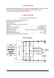
2.2 CONTROL UNIT
2.2.a Microswitches
- The microswitches must have a contact resistance lower than 0.1Ω and a leakage
current lower than 100µA.
- When full load connected, the voltage between the key switch contacts must be lower
than 0.1V.
- The microswitches send a voltage signal to the microprocessor when a function
request (for ex.: running request) is made.
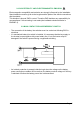
2.2.b Accelerator unit
The accelerator unit can consist of a potentiometer or an Hall effect device.
It should be in a 3-wire configuration.
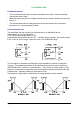
CPOT (B10) signal ranges from 0 to 10V.
Potentiometer value should be in the 0.5 - 10 Kohm range; generally, the load should be
in the 1.5mA to 30 mA range. Faults can occur if it is outside this range.
The Procedure for automatic potentiometer signal aquisition is carried out using the
Console. This enables adjustment of the minimum and maximum useful signal level
(PROGRAM VACC function), in either direction. This function is unique when it is nec-
essary to compensate for asymmetry with the mechanical elements associated with the
potentiometer, especially relating to the minimum level.
The sequence of procedure is described in the programming console manual.