
Specifications
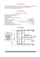


2=CA#
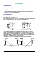
The two graphs show the output voltage from a non-calibrated potentiometer with
respect to the mechanical zero of the control lever. MI and MA indicate the point where
the direction switches close. 0 represents the mechanical zero of the rotation.
The Left Hand graph shows the relationship of the motor voltage without signal
aquisition being made. The Right Hand Graph shows the same relationship after signal
aquisition of the potentiometer.
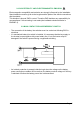
2.2.c Other analog control unit
Input A18 is an analog input, whose typical application is for proportional braking. It
should be in a 3 wire configuration. Potentiometer value should be in the 0.5-10KW
range. Generally, the load should be in the 1.5mA to 30 mA range.
The CPOTB (A18) signal range is from 0 to 10V.
2.2.d Speed feedback
The motor control is based upon the motor speed feedback. The speed trasducer is an
incremental encoder, with two phases shifted at 90°. The encoder can be of different
types :
- power supply: +5V or +12V
- electric output: open collector ( NPN or PNP), push-pull.
For more details about encoder installation see also chapter 3.6.