
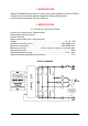
Specifications


2=CA&
2.5 DIAGNOSIS
The microprocessor continually monitors the inverter and carries out a diagnostic proce-
dure on the main functions. The diagnosis is made in 4 points
1) Diagnosis on key switch closing that checks: watchdog circuit, current sensor, ca-
pacitor charging, phase's voltages, contactor drives, can-bus interface, if the switch
sequence for operation is correct and if the output of accelerator unit is correct.
2) Standby diagnosis at rest that checks: watchdog circuit, phase's voltages, contactor
driver, current sensor, can-bus interface.
3) Diagnosis during operation that checks: watchdog circuits, contactor driver, current
sensors, can-bus interface.
4) Continuos diagnosis that check: temperature of the inverter, motor temperature.
Diagnosis is provided in two ways. The digital console can be used, which gives a
detailed information about the failure; the failure code is also sent on the Can-Bus.
2.6 THERMAL CONSIDERATION
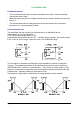
- The heat generated by the power block must be dissipated. For this to be possible,
the compartment must be ventilated and the heat sink materials ample.
- The heat sink material and system should be sized on the performance requirement
of the machine. Abnormal ambient air temperatures should be considered. In situa-
tions where either ventilation is poor, or heat exchange is difficult, forced air ventila-
tion should be used.
- The thermal energy dissipated by the power block module varies and is dependent
on the current drawn and the duty cycle.
2.7 GENERAL INSTRUCTIONS AND PRECAUTIONS .
- Never connect SCR low frequency chopper with ASYNCHRONOUS INVERTER
because the ASYNCHRONOUS filter capacitors alter the SCR choppers' work. If it is
necessary to use two or more control units (traction + lift. for ex.), they must belong to
the ZAPIMOS family.
- Do not connect the inverter to a battery with a nominal value different from the value
indicated on the chopper plate. If the battery value is greater, the MOS may fail; if it is
lower, the control unit does not "power up".
- During battery charge, disconnect ASYNCHRONOUS from the battery.
- Supply the ASYNCHRONOUS only with battery for traction; do not use a power
supply.
- When the chopper is installed, make tests with the wheels raised from the ground, in
order to avoid dangerous situations due to connection errors.
- After the chopper is switched off (key off), the filter capacitor remains charged for
some minutes; if you need to work on the inverter, discharge them using a
10Ω ÷ 100Ω resistance connected from the +Batt to the -Batt.