RDM Series MURS Two-Way Radios User Guide RDM2080d RDM2020
CONTENTS Safety . . . . . . . . . . . . . . . . . . . . . . . . . . . . . . iv Batteries and Chargers Safety Information . . . . . . . . . . . . . . . . . . . .v Introduction . . . . . . . . . . . . . . . . . . . . . . . . .1 FCC Licensing Information . . . . . . . . . . . . . . . . . . . . . . . . . .3 Radio Overview . . . . . . . . . . . . . . . . . . . . . .4 Display Model – RDM2080d . . . . . . . . . . . . . .4 Non-Display Model – RDM2020 . . . . . . . . . . . . . . . . . . . . . . . . . . . .
CONTENTS Battery Type Settings (RDM2080d Model) . . . . . . . . . . . . . . . . . . . .32 Channel Alias (RDM2080d Model) . . . . . . . . . . . . . . . . . . . .32 Clonning Mode . . . . . . . . . . . . . . . . . . . . . . .33 Roger Beep Tone (End of Transmission Tone) . . . . . . . . . . . . .34 Keypad Beep (RDM2080d Model) . . . . . . . . . . . . . . . . . . . . . . . . . . . . . .34 Keypad Lock/Unlock (RDM2080d Model) . . . . . . . . . . . . . . . . . . . . . . . . . . . . . .
Frequency and Code Charts . . . . . . . . . . .50 Use and Care . . . . . . . . . . . . . . . . . . . . . . .57 CONTENTS Troubleshooting . . . . . . . . . . . . . . . . . . . . .58 Motorola Limited Warranty for the United States and Canada . . . . . . . . . .62 Accessories . . . . . . . . . . . . . . . . . . . . . . . .
SAFETY PRODUCT SAFETY AND RF EXPOSURE COMPLIANCE SAFETY Caution English iv Before using this product, read the RF energy awareness information and operating instructions in the Product Safety and RF Exposure booklet enclosed with your radio to ensure compliance with RF energy exposure limits. For a list of Motorola-approved, batteries, and other accessories, visit the following website: www.motorola.
BATTERIES AND CHARGERS SAFETY INFORMATION 3. To reduce risk of damage to the electric plug and cord, pull by the plug rather than the cord when disconnecting the charger. 4. An extension cord should not be used This document contains important safety and operating instructions. Read these instructions carefully and save them for future reference. unless absolutely necessary.
7. To reduce risk of electric shock, unplug connected should be nearby and easily accessible. • Turn the radio OFF when charging battery. • The charger is not suitable for outdoor use. Use only in dry locations/conditions. BATTERIES AND CHARGERS SAFETY INFORMATION English Connect charger only to an appropriately fused and wired supply of the correct voltage (as specified on the product).
INTRODUCTION Business Radios, 8000 West Sunrise Boulevard Note: Read this user guide carefully to ensure you know how to properly operate the radio before use. INTRODUCTION RPSD 1C15, Motorola Thank you for purchasing the Motorola® RDM Series MURS Two-Way Radio. This radio is a product of Motorola's more than 75 years of experience as a world leader in the designing and manufacturing of communications equipment.
INTRODUCTION English For a copy of a large-print version of this user guide or for product-related questions, contact: 1-866-522-5210 on your TTY (Text Telephone) 1-800-448-6686 in the USA For product information visit us at: www.motorola.
FCC LICENSING INFORMATION REGULATION ON MURS (MULTI-USE RADIO SERVICE) FREQUENCIES 1. This device does not cause harmful interference, and 2. This device must accept any interference received, including interference that may cause undesired operation. FCC License is not required. This device operates on frequencies authorized for use in the Multi-Use Radio Service (MURS). MURS frequencies are available for unlicensed business or personal use.
RADIO OVERVIEW DISPLAY MODEL – RDM2080d Fixed Antenna Lithium-Ion Battery On/Off/ Volume Knob LED Indicator Accessory Connector Microphone PTT (Push-to-Talk) Button RADIO OVERVIEW Model Label Menu Button/ Keypad Lock English Use and to scroll up/ down through channels and menu setting SB1 – Monitor Button SB2 – Nuisance Channel Delete Front Buttons 4
NON-DISPLAY MODEL – RDM2020 Fixed Antenna Microphone Channel Selector Knob On/Off/Volume Knob LED Indicator PTT (Push-to-Talk) Button SB1 – Monitor Button Model Label SB2 – Nuisance Channel Delete 5 RADIO OVERVIEW Accessory Connector Lithium-Ion Battery English
On/Off/Volume Knob Front Buttons (RDM2080d Model Only) Used to turn the radio ON or OFF and to adjust the radio’s volume. Channel Selector Knob Used to switch the radio to different channels. Accessory Connector Used to connect compatible audio accessories. Microphone Speak clearly into the microphone when sending a message. RADIO OVERVIEW Fixed Antenna The antenna is not removable. • Button This button provides access to set up features like VOX/iVOX levels, battery type, etc.
Configurable Buttons Button SB1 SB2 BUTTON A (*) BUTTON C (*) Scan / Nuisance Delete Call Tone Default Default Scramble Backlight Channel Preset 1 Channel Preset 2 N/A N/A N/A N/A N/A N/A No Operation Default Default Default Buttons are configured to default functions, other features may be assigned to these buttons as shown in the table.
Icons Chart (RDM2080d Model) RADIO OVERVIEW Icon English Symbol Comments Battery Level Displayed during normal radio mode operation, displays battery life remaining. Channel Displayed during normal radio operation and when programming channel features. Code Displayed during normal radio operation and when programming codes features. Frequency Displayed during normal radio operation. Keypad lock Displayed whenever the Keypad lock feature is enabled (keypad is locked).
BATTERY FEATURES The RDM Series MURS Two-Way Radio provides Lithium-Ion batteries that come in different capacities that will define the battery life. It also offers the option to use Alkaline batteries. About the Li-Ion Battery The RDM Series MURS Two-Way Radio comes equipped with a rechargeable Li-Ion battery. This battery should be charged before initial use to ensure optimum capacity and performance. Battery Recycling and Disposal Li-Ion rechargeable batteries can be recycled.
Many retailers and dealers participate in this program. For the location of the drop-off facility closest to you, access RBRC's Internet web site at: DROP-IN TRAY CHARGER AND POWER SUPPLY http://www.call2recycle.org/ or call: 1-800-8-BATTERY RADIO OVERVIEW This internet site and telephone number also provides other useful information concerning recycling options for consumers, businesses and governmental agencies.
Installing the Battery Removing the Battery Battery Latch Battery Latch slots Turn OFF the radio. 1. Turn OFF the radio. 2. With the Motorola logo side up, fit the tabs at 2. Push down and hold the battery latch. the bottom of the battery into the slots at the 3. Pull the top of the battery out and lift it from the bottom of the radio. 3. slots located at the bottom of the radio. Press the top part of the battery towards the radio until a click is heard. 11 RADIO OVERVIEW 1.
Alkaline Battery Pack (Optional) Installing Alkaline Batteries Removing Alkaline Batteries Alkaline Battery Door RADIO OVERVIEW 1. Turn OFF the radio and remove the Li-Ion battery. 2. Assemble alkaline battery frame in the same steps as installing the Li-Ion battery. 3. Pull the battery door from alkaline battery frame out and slide five AA alkaline batteries into the frame, matching the markings inside the compartment. 4. English Replace the battery door on the battery frame.
Li-Ion Battery Life When the Battery Save feature is ON (enabled by default) the battery life will be longer. The following chart summarizes battery life estimations: Li-Ion Battery Life with Battery Save feature ON Battery Type 2 Watts Standard 12 hours High 24 hours Ultra High 26 hours RADIO OVERVIEW Note: Battery life is estimated based on the following standard duty cycle: 5% Transmit, 5% Receive and 90% Standby.
Alkaline Battery Life The following chart estimates the Alkaline battery life: Alkaline Battery Life RADIO OVERVIEW Note: English 14 Battery Save Feature 2 Watts ON 26 hours Battery life is estimated based on the following standard duty cycle: 5% Transmit, 5% Receive and 90% Standby.
Battery Meter (RDM2080d Model) The battery meter located in the upper left corner of the display model indicates the remaining battery power.
CHARGING THE BATTERY Charging The Battery Attached to the Radio The RDM Series MURS Two-Way Radio offers a Standard Charger and a Rapid Charger, which are designed to charge either the battery with the radio or a standalone battery. Power Supply (Transformer) The RDM radio comes equipped with a Standard Charger. Use only use Motorola-approved Drop-in Tray Single Unit Charger or Drop-in Tray Multi Unit Charger to charge the Motorola-approved battery.
Charging a Standalone Battery Charging a Standard Battery The drop-in tray charger has a removable bracket that is adjustable depending on the type of battery that needs to be charged. The drop-in tray charger's default position will charge a standard battery.
Charging a High Capacity or Ultra High Capacity Battery The bracket in the charger must be adjusted to the correct position for either Standard or High capacity battery. Removable Piece Removable Piece To adjust the charger to accommodate the High capacity or Ultra High capacity battery: 1. Squeeze both tabs on each side of the removable bracket in the drop-in charger tray and lift the bracket from the tray. 2.
Drop-in Tray Charger LED Indicators Standard Charger LED Indicator Status LED Status Comments Power ON Steady red for 3 seconds The charger has powered up Charging Blinking red (slow) The charger is currently charging Charging Complete Steady red Battery is fully charged Battery Fault(*) Blinking red (fast) Battery had a fault when it was inserted RADIO OVERVIEW (*) Normally re-seating the battery will correct this issue.
Rapid Charger LED Indicator RADIO OVERVIEW Status English LED Status Comments Power ON Steady green for 3 seconds The charger has powered up Charging Blinking green The charger is currently charging Top-off Charging Blinking green (slow) Battery is near fully charged Charge Complete Steady green Battery is fully charged Battery Fault (*) Blinking red (fast) Battery had a fault when it was inserted Waiting to Charge (**) Double-blink yellow Battery charging conditions not suitable (*) N
Estimated Charging Time The following table provides the estimated charging time of the battery. For further details, see "Battery” on page 66. Estimated Charging Time Battery Type Charging Solution Standard Charging Solution High Capacity Ultra High Capacity 7 hours 12 hours 13 hours 1.5 hours 3 hours 3.
Charging Batteries using a Multi Unit Charger- MUC (Optional) MUC LED Indicator Status RADIO OVERVIEW The Multi Unit Charger (MUC) allows drop-in charging of up to 6 batteries with radios attached or stand alone batteries. To charge the batteries follow the same procedure described for the Single Unit Charger. Note: English The Multi Unit Charger is capable of cloning up to 3 radios (3 Source radios and 3 Target radios). See "RADIO Cloning” on page 30 for details.
INSTALLING SPRING ACTION BELT CLIP Belt Clip Tab Spring Action Belt Clip 1. Slide the spring action belt clip rails into the belt clip grooves on the back of the battery and slide it down until the belt clip tab snaps into place. RADIO OVERVIEW 2. To remove, pull back the metal release tab on the belt clip tab and push the spring action belt clip upward to remove. (If needed, use a small flat screw driver to leverage the metal release).
GETTING STARTED GETTING STARTED READING THE DISPLAY (RDM2080d MODEL) TURNING RADIO ON/OFF Keypad Lock Turn the On/Off/Volume knob clockwise to turn ON the radio. The radio will chirp and the LED will briefly blink a red light. Vox / iVox Scan Signal Strength To turn the radio OFF rotate the On/Off/Volume knob counterclockwise until you hear a “click” and the radio LED indicator turns OFF.
RECEIVING A CALL To select a channel on the RDM2080d model, press the toggle / buttons until you reach the desired channel. 1. Select a channel by pressing the toggle buttons 2. Make sure the PTT button is released and listen 3. The LED indicator blinks RED while your radio 4. To respond, hold the radio vertically 1 to 2 To select a channel on the RDM2020 model, rotate the Channel Selector Knob and select either Channel 1 or 2.
GETTING STARTED Whenever the radio is set up in “Scan Mode” If there is transmission in another channel during this time, the radio will stay on the active channel and the transmission on the other channel will not be heard. When the transmission is over in the active channel, the radio will wait for 5 seconds before resuming Scan again. 2. To scan a channel without Interference Eliminator Codes (CTCSS/DPL), set the code for the channels to ‘0’ in the CTCSS/DPL Advanced Configuration Mode.
LOW BATTERY ALERT TALK RANGE Industrial Multi-Level Inside steel/concrete Inside multi-level Industrial buildings buildings Up to 220,000 Sq. Ft. Up to 13 Floors 27 GETTING STARTED This feature provides a sequence of loud and high beep tones to alert that the battery level is low. The LED blinks orange several times. The RDM2080d also provides a battery gauge icon on the screen that indicates the battery level as shown in the previous image.
GETTING STARTED COMPUTER PROGRAMMING SOFTWARE In addition to the features that can be configured in Basic and Advanced Configuration via the radio panel, the Computer Programming Software (CPS) can additionally configure Transmit Time-Out Timer, PL Reverse Burst, Alternate Battery Selection, Backlight settings, Buttons Reset, CPS Manager Lock, LED enabled/disabled, Power Up Text, and Edit Scan List. The Programming Cable RKN4155 (sold separately) is required.
Alternate Battery Selection PL Reverse Burst causes a Private Line (PL) code to be sent at the end of a transmission once the PTT button is released. This subaudible tone causes the receiving radio to mute its speaker before loss of a carrier is detected. Muting the speaker eliminates unwanted noise (squelch tail) during loss of carrier detection.
GETTING STARTED RADIO CLONING The RDM Series MURS Two-Way radio profiles from one radio (the “Source” radio) to a second radio (the “Target” radio) by using any one of these 3 methods: • One Multi Unit Charger (optional accessory) • Two Single Unit Chargers and a Radio-toRadio cloning cable (optional accessory) • the CPS (free software download) Cloning with a Multi-Unit Charger (MUC) The Source radio has to be in Pocket 1, 3 or 5 while the Source radio to be cloned has to be in Pockets 2, 4 or 6, ma
BASIC CONFIGURATION MENU OPTIONS (RDM2080d MODEL) The menu options only activate whenever there is an audio accessory connected to the radio, iVOX is enabled and/or a battery type has been changed. BATTERY SAVE This feature extends the battery life by placing the radio in “Idle” mode each time there is no radio activity. The battery safe feature default setting is set ON. To toggle Battery Save on/off: 1. Press SB1 and SB2 simultaneously for 2 or 3 seconds while powering up the radio until a 1.
BATTERY TYPE SETTINGS (RDM2080d MODEL) Only if the battery pack is not detected, the radio will enable the battery type setting to select either Lithium-Ion or Alkaline. To change battery settings: 1. CHANNEL ALIAS (RDM2080d MODEL) This feature allows the editing of the channel name or alias. To configure channel alias: 1. Press the MENU button as many times as emit a special beep. needed until the radio shows the current battery BASIC CONFIGURATION simultaneously while turning radio ON for 3 sec.
4. Use button B to move the cursor to the left. Note: 7. If the radio is left idle for more than 3 seconds, the current character will be accepted and the cursor will advance one space to the right. Long press the PTT button to save and go back to the “Channel Aliasing Selection Mode” to edit other channel alias name, -- or -- 5. When the cursor is located in the first character, the radio produces a bonk tone.
To enable/disable Cloning Mode: tone is heard, which indicates that Roger Beep 1. Tone is OFF. Press PTT and SB2 buttons while turning the radio ON. Note: The RDM2080d emits a distinctive sound and shows the word CLONE on the display. The RDM2020 emits a distinctive sound and BASIC CONFIGURATION the LED indicates two orange heartbeats 2. Turn the radio OFF and back ON to disable Cloning mode. Note: See "RADIO Cloning" on page 30 for more details.
KEYPAD LOCK/UNLOCK (RDM2080d MODEL) The keypad can be locked to avoid accidental changes in the radio settings. The keypad lock default setting is set to UNLOCKED. When the keypad is locked, an icon is displayed on the screen. VOX - VOICE OPERATED TRANSMIT Enables the radio to automatically transmit due to recognition of voice. The radio automatically stops transmitting when audio is no longer present. Before using this feature, the VOX level must be configurated via the CPS.
6. To receive, stop talking. 1. Press and hold the PTT button while turning the radio ON. The display will show the 2. icon. To transmit, talk directly into the microphone without pressing the PTT button. There is a short threshold in the transmission that can be adjusted by changing the iVOX level in the BASIC CONFIGURATION CPS. VOX Accessory Accessory Connector Note: VOX can be temporarily disabled by pressing the PTT button or removing the audio accessory.
set to OFF and the default sensitivity value for iVOX is set to Medium. 0 = OFF (For VOX accessories only) To configure VOX/iVOX sensitivity: 2 = Medium sensitivity 1. 1 = Low sensitivity 3 = High sensitivity Short press the MENU button and navigate until 3. the following screens are displayed: Long press the PTT button to save and exit, If iVOX is enabled the radio will display the --or-- short press the PTT button to configure following: the next feature without saving.
Note: The next time Scanning is enabled, the channel will be back in the scanning list. PL DEFEAT Also known as “Squelch defeat”, this feature allows to listen or monitor any activity in the channel without noise. BASIC CONFIGURATION To toggle PL Defeat on/off: English 1. Short press SB1 to enable PL/DPL defeat. 2. Short press SB1 again to disable PL/DPL defeat. 38 RESET TO FACTORY DEFAULTS Reset to Factory Defaults will set back all radio features to the original factory default settings.
ADVANCED CONFIGURATION Advanced Configuration is an optional configuration mode that allows the customization of additional features via the front panel. To establish a proper two-way communication, the Channel, Frequency, and Interference Eliminator Code must be the same on both radios, which will depend on the stored profile that has been pre configured on the radio. To enter Advanced Configuration Mode, press and hold both PTT and SB1 buttons simultaneously for 3 to 5 seconds while turning radio ON.
ADVANCED CONFIGURATION (RDM2080d MODEL) or PTT Button RX or PTT Button ADVANCED CONFIGURATION Select a preset Frequency from 1 to 5 English RX Select a preset Code from 001 to 213 or PTT Button YES Set up Scan Select the channel by pressing / Toggle SB2 for YES/NO Continue customizing channels 2 to 8 Notes: To save changes long press the PTT button. The radio will return to “Idle” Advanced Configuration Mode.
OTHER ADVANCED CONFIGURATIONS (RDM2080d MODEL ONLY) Call Tone Long press the PTT button to save and exit, --or-- short press the PTT button to configure the next feature without saving. Microphone Gain Level This feature sends an alert notification to other radios in the fleet prior to the transmission with the intent to grab the receiver’s attention so the transmission is not missed. In order to configure this feature via the front panel, it must first be enabled via the CPS. To configure call tones: 1.
2. Select the desired microphone gain level by 3. pressing the / buttons (1 = low gain, 2 = Medium gain or 3 = high gain). 3. Long press the PTT button to save and exit, --or-- short press the PTT button to configure the next feature without saving. To configure Accessory Microphone Gain: 1.
2. Scroll up/down through the configuring options by short pressing the PTT button, until the screen shows the image below: Side Button Preset to Channel Select Any channel can be mapped to either button B or C as a preset channel. To map a channel to a side button: 1. Enter “Advanced Configuration Mode” and choose the channel to be preset using the / The current scramble setting will blink. 3. Select the desired scramble value (0,1,2 or 3) by pressing the 4. / 2. buttons.
ADVANCED CONFIGURATION (RDM2020 MODEL) Before start configuration, the channel must be selected. This can be done before or at any time during the Advanced Configuration Mode by turning the Channel Selector knob to the desired channel.
Reading Values Through Beeps and LED Indicators As the RDM2020 model does not have a display to show the values that are being configured, the radio will communicate this information using beeps and LED indications.
Reading Frequency Values Reading CTCSS/DPL Values The Frequency value is only one digit as RDM Series MURS Two-Way radios have 5 predefined frequencies. When reading the values for CTCSS/PL Codes the radio signals the digit codes each time the PTT button is short pressed. The RDM Series have up to 213 codes available (Refer to "Frequency and Code Charts" on page 50). To read frequency values: 1.
2. Short press PTT button again and the radio signals the second digit “1”. 3. Short press PTT again and radio signals the third digit “8”. Reading Auto-Scan Values After finishing reading CTCSS/DPL codes, if you short press PTT once again, the radio takes you to Auto-Scan as per “Advanced Configuration (RDM2020 Model)” on page 44 (Step 3).
ADVANCED CONFIGURATION English Configuring a Frequency Configuring a Code Assuming current frequency value is set up to channel 1, with the MURs default frequency “1” (equivalent to 154.60000 MHz), and it will be changed to Frequency Number = “4” (which is mapped to 151.88000 MHz), follow the sequence below: Assuming current code value is set to factory default “001”, and it will be changed to CTCSS/ DPL Code = 103 follow the sequence below: 1. Enter Advanced Configuration Mode. 2.
7. Long press the PTT button to save changes and return to “Idle” Advanced Configuration Mode. Once in “Idle” Advanced Configuration Mode, LED indicator will start blinking a green heartbeat. 8. Long press the PTT button to exit Advanced Configuration Mode. Configuring Auto-Scan Auto-Scan is the last Advanced Configuration Mode and can be set to “ON” or “OFF” on a particular channel. To set Auto-Scan to “ON”: Enter Advanced Configuration Mode and select the desired channel. 2.
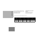
FREQUENCY AND CODE CHARTS FREQUENCY AND CODE CHARTS RDM SERIES MURS FREQUENCY CHART RDM2080d MURS Display Model – Default Frequencies and Codes Channel Frequency (MHz) Code # Code Value Channel Name/Alias Bandwidth 1 154.570 1 67.0 Hz Channel 1 20.0 kHz 2 154.600 1 67.0 Hz Channel 2 20.0 kHz 3 151.820 1 67.0 Hz Channel 3 11.25 kHz 4 151.880 1 67.0 Hz Channel 4 11.25 kHz 5 151.940 1 67.0 Hz Channel 5 11.25 kHz 6 154.570 0 CSQ Channel 6 20.0 kHz 7 154.
RDM2020 MURS Non-Display Model – Default Frequencies and Codes Frequency (MHz) Code # Code Value Channel Name/Alias Bandwidth 1 154.570 1 67.0 Hz Channel 1 20.0 kHz 2 154.600 1 67.0 Hz Channel 2 20.
CTCSS AND PL/DPL CODES FREQUENCY AND CODE CHARTS CTCSS Codes CTCSS Hz CTCSS Hz CTCSS Hz 1 67.0 14 107.2 27 167.9 2 71.9 15 110.9 28 173.8 179.9 3 74.4 16 114.8 29 4 77.0 17 118.8 30 186.2 5 79.7 18 123 31 192.8 6 82.5 19 127.3 32 203.5 7 85.4 20 131.8 33 210.7 8 88.5 21 136.5 34 218.1 9 91.5 22 141.3 35 225.7 10 94.8 23 146.2 36 233.6 11 97.4 24 151.4 37 241.8 12 100.0 25 156.7 38 250.3 103.5 26 162.2 122 (*) 69.
Code DPL Code DPL Code 39 23 55 116 71 243 40 25 56 125 72 244 41 26 57 131 73 245 42 31 58 132 74 251 43 32 59 134 75 261 44 43 60 143 76 263 45 47 61 152 77 265 46 51 62 155 78 271 47 54 63 156 79 306 48 65 64 162 80 311 49 71 65 165 81 315 50 72 66 172 82 331 343 51 73 67 174 83 52 74 68 205 84 346 53 114 69 223 85 351 54 115 70 226 86 364 FREQUENCY AND CODE CHARTS PL/DPL Codes (cont.
FREQUENCY AND CODE CHARTS PL/DPL Codes (cont.
PL/DPL Codes (cont.
FREQUENCY AND CODE CHARTS PL/DPL Codes (cont.
USE AND CARE Do not immerse in water USE AND CARE Use a soft damp cloth to clean the exterior Do not use alcohol or cleaning solutions If the radio is submerged in water...
TROUBLESHOOTING Symptom Try This... Recharge or replace the Li-Ion battery. No Power Reposition or replace AA batteries. Extreme operating temperatures may affect battery life. Refer to See “About the Li-Ion Battery” on page 9. Confirm Interference Eliminator Code is set. Hearing other noises or conversation on a channel Frequency or Interference Eliminator Code may be in use. Change settings: either change frequencies or codes on all radios.
Symptom Try This... Steel and/or concrete structures, heavy foliage, buildings or vehicles decrease range. Check for clear line of sight to improve transmission. Wearing radio close to body such as in a pocket or on a belt decreases range. Change location of radio. To increase range and coverage, you can either Limited talk range reduce obstructions or use UHF radio instead of VHF MURS radio. UHF radios provide greater coverage in industrial and commercial buildings. (FCC license may be required).
Symptom Try This... Radios are too close; they must be at least five feet apart. Heavy static or interference Radios are too far apart or obstacles are interfering with transmission. Refer to “Talking and Monitoring” on page 25. Recharge or replace Li-Ion battery. Replace AA batteries. Low batteries Extreme operating temperatures affect battery life. Refer to “About the Li-Ion Battery” on page 9.
Symptom Try This... VOX feature might be set to OFF. Cannot activate VOX Use the CPS to ensure that the VOX Sensitivity level is not set to ‘0’. Accessory not working or not compatible. Refer to the “VOX” section on page 35. Check drop-in tray charger is properly connected and correspond to a compatible power supply. Battery does not charge Ensure that you have the drop-in tray charger adjustable piece placed on the although it has been placed in right position.
WARRANTY MOTOROLA LIMITED WARRANTY FOR THE UNITED STATES AND CANADA What Does this Warranty Cover? Subject to the exclusions contained below, Motorola, Inc.
Exclusions Use of Non-Motorola Products and Accessories. Defects or damage that result from the use of Non-Motorola branded or certified Products, Accessories, Software or other peripheral equipment are excluded from coverage. Unauthorized Service or Modification. Defects or damages resulting from service, testing, adjustment, installation, maintenance, alteration, or modification in any way by someone other than Motorola, or its authorized service centers, are excluded from coverage. Altered Products.
WARRANTY Communication Services. Defects, damages, or the failure of Products, Accessories or Software due to any communication service or signal you may subscribe to or use with the Products Accessories or Software is excluded from coverage. Software. Applies only to physical defects in the media that embodies the copy of the software (e.g. CDROM, or floppy disk). Length of Coverage Ninety (90) days from the date of purchase. Software Embodied in Physical Media.
EXPORT LAW ASSURANCES This product is controlled under the export regulations of the United States of America. The Governments of the United States of America may restrict the exportation or re-exportation of this product to certain destinations. For further information contact the U.S. Department of Commerce. PATENT NOTICE This product is covered by one or more of the following United States patents.
ACCESSORIES Part No. AUDIO ACCESSORIES Part No.
POWER SUPPLIES AC PIN ADAPTORS Part No. RLN6349 Description CHARGERS Part No. North America AC Pin Adaptor Rapid Accessory Charging Kit (includes Power Supply, Drop-in Tray Charger, and AC Pin adaptor). Description RLN6309 Multi Unit Charger (MUC) RVN5147 Computer Programming Software (CPS) RLN6175 Standard Drop-in Tray Charger POWER SUPPLIES CABLES Part No. ACCESSORIES RLN6304 SOFTWARE APPLICATIONS Part No.
ACCESSORIES Notes English 68
M Motorola Inc. 1301 E. Algonquin Rd. Schaumburg, IL 60196-1078 U.S.A. MOTOROLA, the RDM Series MURS Radio and the Stylized M Logo are registered in the US Patent & Trademark Office. All other product or service names are the property of their respective owners. © 2010 by Motorola, Inc. All rights reserved. Printed in Malaysia.