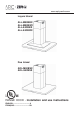
www.zephyronline.com Layers Island ALL-M90BBX ALL-M90BWX ALL-E42BBX ALL-E42BWX Duo Island ADL-M90BSX ADL-E42BSX RANGE HOOD - Installation and use instructions ENGLISH........................................3 FRANÇAIS...................................
-2-
Table of contents Safety Instructions.............................................. Page 4 - 5 List of Materials.................................................. Page 6 - 7 Ducting Calculation Sheet.................................... Page 8 Hood Specifications............................................. Page 9 - 10 Wiring Diagram.................................................... Page 11 Cleaning and Maintenance.................................... Page 12 Remote Control.................................
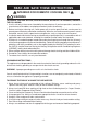
READ AND SAVE THESE INSTRUCTIONS ! INTENDED FOR DOMESTIC COOKING ONLY ! WARNING TO REDUCE THE RISK OF FIRE, ELECTRIC SHOCK, OR INJURY TO PERSONS, OBSERVE THE FOLLOWING: 1. Use this unit only in the manner intended by the manufacturer. If you have questions, contact the manufacturer at the address or telephone number listed in the warranty. 2. Before servicing or cleaning unit, switch power off at service panel and lock service panel to prevent power from being switched on accidentally.
WARNING TO REDUCE THE RISK OF INJURY TO PERSONS IN THE EVENT OF A RANGE TOP GREASE FIRE, OBSERVE THE FOLLOWING:* 1. SMOTHER FLAMES with a close-fitting lid, cookie sheet, or metal tray, then turn off the burner. BE CAREFUL TO PREVENT BURNS. If the flames do not go out immediately, EVACUATE AND CALL THE FIRE DEPARTMENT. 2. NEVER PICK UP A FLAMING PAN - You may be burned. 3. DO NOT USE WATER, including wet dishcloths or towels - violent steam explosion will result. 4. Use an extinguisher ONLY if: A.
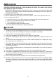
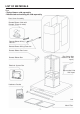
LIST OF MATERIALS Layers - Zephyr blower sold separately - Non-ducted recirculating kit sold separately Duct Cover Assembly Remote Blower Collar with Damper (External motor) Remote Blower Wiring Harness Remote Blower Wiring Extension Remote Blower Box Cover Box Cover (box marked “120 VAC Input”) Remote Blower Box Electrical System Box Box marked “120 VAC Input” Glass Hardware Packet Led Mesh Filter -6-
LIST OF MATERIALS Duo - Zephyr blower sold separately - Non-ducted recirculating kit sold separately Duct Cover Assembly Remote Blower Collar with Damper (External motor) Remote Blower Wiring Harness Remote Blower Wiring Extension Remote Blower Box Cover Box Cover (box marked “120 VAC Input”) Remote Blower Box Electrical System Box Box marked “120 VAC Input” Hardware Packet Led Mesh Filter -7-
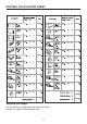
DUCTING CALCULATION SHEET Maximum Duct Length: For satisfactory air movement, the total duct length should not exceed 100 equivalent feet.
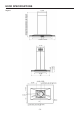
HOOD SPECIFICATIONS Layers -9-
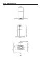
HOOD SPECIFICATIONS Duo - 10 -
WIRING DIAGRAM - 11 -
CLEANING AND MAINTENANCE Proper maintenance of the Range Hood will assure proper performance of the unit. Motor The motor is permanently lubricated and never needs oiling. If the motor bearings make excessive or unusual noise, replace the motor with the exact service motor. The impeller should also be replaced. Mesh Filters The mesh filters should be cleaned frequently. Using warm water with detergent. Mesh filters are dishwasher safe.
REMOTE CONTROL SYNCHRONIZATION: To synchronize the remote control with the range hood for the first time, proceed as follows: 1. With range hood off, press and hold the “light” button on the range hood until the light indicator begins to flash (approximately 3 seconds) (Fig.1). 2. Press the “light” button more times on the remote control until the lights on the hood turn on (Fig.2). The range hood may now be activated using the remote control. If you experience any problems, repeat the procedure.
CONTROLS E A B F G H I C D A: Power button - Power Button will turn power on and off for the entire hood (fan and lights). - Hood will remember the last speed and light level it was last turned off at.(Example: hood is turned off at when it was last on high speed and high lights; hood will turn back on at high speed and high lights when Power Button is pressed). B: Fan Speed button - From off, press once for low speed (1), twice for medium (2), and three times for high (3).
fan usage indicating it is time to replace the charcoal filter. Indicator light will blink, it will not remain illuminated. - This function must be reset by the user. With hood off, hold the Delay Off Button for five seconds, after five seconds the Filter Clean Indicator will stop blinking and turn off and the 120 hour timer will reset. Order replacement charcoal filter kit number Z0F-01AC through your local dealer, www.zephyronline.com or the Zephyr customer service department.
INSTALLING THE DUCTWORK: INTERNAL BLOWER ROOF CAP NOTE: To reduce the risk of fire, use only metal ductwork. 1. Decide where the ductwork will run between the hood and the outside. 2. A straight, short duct run using a minimum 6” round duct will allow the hood to perform most efficiently. 3. Long duct runs, elbows, and transitions will reduce the performance of the hood. Use as few of them as possible. 4. Install a roof cap. Connect round metal ductwork to cap and work back towards hood location.
INSTALLING THE INTERNAL BLOWER NOTE: The following instructions are for installing the internal blower only. Install this range hood only with internal blower model CBI-290A or CBI-600A. 1. Remove the 6” metallic flange provided on the blower’s air outlet (the flange may already be pre-installed) (Fig.8). 2. Remove the blower plate unscrewing the (4) 3.9x9.5 mm screws (Fig.9). 3. Install internal blower into blower plate and secure using (4) screws (Fig.10). 4. Install assembly blower by means (8) 3.
INTERNAL BLOWER WIRING A Note: This range hood must be properly grounded. The unit should be installed by a qualified electrician in accordance with all applicable national and local electrical codes. 1. Secure capacitor box screwing the (2) 3.9x9.5 mm screws (Fig.13A) 2. Make connections (B,C, D) (Fig.13). 3. Remove the wiring box cover. Remove a knockout from the wiring box (Fig.14E). 4. Secure the conduit to the wiring box through a conduit connector. 5. Make electrical connections.
REMOTE BLOWERS (EXTERNAL AND IN-LINE) CAUTION: To reduce risk of fire and electric shock, install this range hood only with External Blower Model CBE-1000, and In-Line Blower Model PBN-1000A. Other blowers cannot be substituited. INSTALLING THE DUCTWORK: REMOTE BLOWER NOTE: To reduce the risk of fire, use only metal ductwork. 1. Choose the location where the External Blower or In-Line Blower will be mounted. See illustrations below for mounting location suggestions and restrictions. 2.
INSTALLING THE REMOTE BLOWER MOUNTING SCREWS 3.9x6mm NOTE: The following instructions are for preparing the hood for use with external or in-line blower models CBE-1000 or PBN1000A. For blower installation details refer to manual included with the blower. 1. Remove the blower plate unscrewing the (4) 3.9x9.5 mm screws (Fig.15). 2. Install the external blower plate and secure using (4) 3.9x6 mm screws (Fig.16) FIG. 15 MOUNTING SCREWS 3.9x6 mm FIG. 16 3.
REMOTE BLOWER WIRING 1. Remove the covers from the wiring boxs and remove one knockouts. 2. Run 4-wire plus ground power cable from the remote blower to the remote blower wiring box marked “motor connection” (Fig.18B). 3. Feed 6” of cable through the knockout opening and secure the cable to the wiring box with an appropriate connector. 4. Make electrical connections at the hood (box marked 120 Vac input). Connect white-towhite, black-to-black, green-to-ground (Fig.18A). 5.
INSTALL SUPPORT SYSTEM DRYWALL Remove the plastic protective film from all exterior surfaces, decorative flues and filters, prior to final installation. CROSS FRAMING 10” 1. At hood location, install 2 x 4 or larger cross framing between ceiling joists using dimensions shown. CEILING JOISTS 2. Finish the ceiling surface. Be sure to mark the location of the ceiling joists and cross framing. 3. Adjust the overall height of the support frame.
INSTALL THE HOOD Insert 8 screws (3.9x6mm), located in the Hardware Package (Fig. 21). DUCTED INSTALLATION ONLY Note: Rooms with 10 to 12 foot ceiling require duct cover extension/support frame model Z1C-02LL, available from your local dealer. Discard the duct covere extension/ support frame supplied with the range hood and replace it with the longer duct cover extension. 1. Run 6-inch diameter metal ductwork to the outside location (Fig.22). 2.
CONNECT THE DUCT COVERS MOUNTING SCREWS 3,9x9,5mm 1. Secure the two upper duct covers to support frame with (4) 3.9 x 9,5 mm screws (Fig.24). Vents may be exposed on 10 to 12 foot ceilings. 2. Secure the two lower duct covers parts to the support frame by overlapping the lateral magnets (Fig.25). UPPER DUCT COVER FIG.24 LOWER DUCT COVER LOWER DUCT COVER MAGNETS FIG.
MESH FILTERS NOTE: prior to use, remove protective film from the filter frame. DUCTED AND NON-DUCTED HOODS 1. To remove the MESH filter, pull down on latch tab to disengage the filter from the hood. Tilt the filter downward and remove (Fig.26). 2. To install the MESH filter, align rear filter tabs with slots in the hood. Pull latch tab down. Push filter into place and release tab. Make sure the filter is securely engaged after installation. NON-DUCTED HOODS ONLY 1.
HOOD DESCRIPTION PART# REPLACEMENT PARTS Metal Mesh Filter ADL 50200031 Metal Mesh Filter ALL 50200033 Recirculating Kit ADL-ALL ZRC-01LL Replacement Charcoal Filters ADL-ALL Z0F-01AC Extension Flue up to 12’ ADL-ALL Z1C-02LL OPTIONAL ACCESSORIES To order parts, visit us online at http://store.zephyronline.com or call us at 1.888.880.
- 27 -
- 28 -
www.zephyronline.
Sommaire Instructions de sécurité........................................ Page 31 - 32 Liste des materiaux..............................................Page 33 - 34 Feuille pour calculer les conduits...........................Page 35 Specifications techniques..................................... Page 36 - 37 Schema electrique.......................................... Page 38 Nettoyage et entretien.......................................... Page 39 Télécommande..............................................
LIRE CES DIRECTIVES ET LES CONSERVER ! CONÇUE POUR LES CUISINES PRIVÉES UNIQUEMENT ! AVERTISSEMENTS POUR RÉDUIRE LES RISQUES D’INCENDIE, D’ÉLECTROCUTION OU DE BLESSURES PHYSIQUES, RESPECTEZ LES INSTRUCTIONS CI-DESSOU: 1. Utilisez cet appareil uniquement de la manière prévue par le fabricant. Si vous avez des questions, contactez le fabricant à l’adresse ou au numéro de téléphone indiqués dans la garantie. 2.
AVERTISSEMENTS POUR RÉDUIRE LE RISQUE DE BLESSURES PHYSIQUES EN CAS DE FEU DE FRITURE SUR LA TABLE DE CUISSON, VEUILLEZ PROCÉDER COMME SUIT :* 1. ÉTOUFFEZ LES FLAMMES avec un couvercle hermétique, une plaque à biscuits ou un plateau en métal, puis éteignez le brûleur. SOYEZ PRUDENT(E) AFIN D’ÉVITER LES BRÛLURES. Si les flammes ne s’éteignent pas immédiatement, ÉVACUEZ LE LIEU ET APPELEZ LE SERVICE DES POMPIERS. 2. NE SAISISSEZ JAMAIS UNE POÊLE ENFLAMMÉE, vous risquez de vous brûler. 3.
LISTE DES MATERIAUX Layers - Le moteur Zephyr est vendu séparément. - Le kit de recirculation est vendu séparément.
LISTE DES MATERIAUX Duo - Le moteur Zephyr est vendu séparément. - Le kit de recirculation est vendu séparément.
FEUILLE POUR CALCULER LES CONDUITS Longueur maximale du conduit : Pour assurer un flux d’air approprié, la longueur maximale d'un conduit, doit pas dépasser une longueur équivalente à 100 piedes.
SPECIFICATIONS TECHNIQUES Layers - 36 -
SPECIFICATIONS TECHNIQUES Duo - 37 -
SCHEMA ELECTRIQUE - 38 -
NETTOYAGE ET ENTRETIEN Pour assurer les performances de l'appareil, entretenez-le de manière appropriée. Moteur Le moteur est lubrifié en permanence et aucun graissage n'est nécessaire. Si les roulements du moteur font un bruit excessif ou inhabituel, remplacez le moteur par une pièce de rechange identique. Remplacez aussi les hélices. Filtre à graisse Le filtre à graisse doit être nettoyé souvent. Vous pouvez utiliser une solution détergente chaude ou le mettre dans le lave-vaisselle.
TELECOMMANDE SYNCHRONISATION: Pour synchroniser la télécommande avec la hotte de la cuisine, pour la première fois, procéder en suivant les indications suivantes: 1. En tenant arrêtée la hotte de la cuisine, appuyer et maintenir appuyée la touche “Eclairage” sur la hotte de la cuisine jusqu’à ce que le voyant commence à clignoter (environ 3 secondes) (Fig.1). 2. Appuyer la touche “Eclairage” sur la télécommande plusieurs fois jusqu’à ce que l’éclairage de la hotte s’allume.
FONCTION DES TOUCHES E A B F H G I C D A: Touche Power - La touche d’allumage / extinction sert à mettre en marche et à arrêter la hotte en entier (tur-bine et lumières).
- Le voyant de nettoyage du filtre s’allume au bout de 30 heures d’utilisation de la turbine et signale la nécessité de procéder au nettoyage du filtre métallique. La lumière du voyant reste allumée au fixe, sans clignoter. - Cette fonction doit être rétablie par l’utilisateur. Avec la hotte à l’arrêt, maintenez la touche Vitesse turbine enfoncée pendant cinq secondes. Au bout de cinq secondes, le voyant de nettoyage du filtre s’éteint et le réglage de 30 heures repart de zéro.
Note2: La fonction d’air propre reste activée même si les lumières sont allumées/éteintes. F : Voyant Vitesse turbine 1 = Petite vitesse 2 = Vitesse moyenne 3 = Grande vitesse - Petite vitesse : seulement le voyant 1 est allumé. - Vitesse moyenne: les voyants 1 et 2 sont allumés. - Grande vitesse : les voyants 1, 2 et 3 sont allumés. - Quand la turbine est à l’arrêt, tous les voyants de vitesse de la turbine sont éteints.
INSTALLER LES CONDUITS (VENTILATEUR INTÉRIEUR) CAPUCHON DU TOIT REMARQUE: pour réduire les risques d’incendie, utilisez uniquement des conduits métalliques. 1. Décidez où le tuyau doit être installé, entre votre hotte et l’extérieur. 2. Un conduit droit et court (l'aide d'un conduit rond de minimum 6”) permettra à votre hotte de fonctionner d’une façon plus efficace. 3. Un conduits long avec des coudes et des transitions réduira le bon fonctionnement de votre hotte. En utiliser le moins possible. 4.
INSTALLATION VENTILATEUR INTÉRIEUR REMARQUE: Les instructions suivantes permettent d’installer le ventilateur intérieur. Installez cette hotte uniquement avec le moteur intérieur modèles CBI-290A600A ou CBI-600A. 1. Retirez la bride métallique de 6”(15cm) fourni sur la sortie d’air de la hotte (la bride peut déjà être pré-installé) (Fig.8). 2. Retirer la plaque du ventilateur en dévissant les vis (4) 3.9x9.5 mm (Fig.9). 3.
INSTALLATION ELECTRIQUE VENTILATEUR INTÉRIEUR A Remarque: Ce modèle de hotte doit être relié à la terre correctement. Cet article devrait être installé par un électricien qualifié selon les lois nationales et locales en matière d’électricité. 1. Fixer la boîte du condensateur au moyens des (2) vis 3.9x9.5 mm (Fig.13A). 2. Faire les connexions (B,C, D) (Fig.13). 3. Enlevez le couvercle de la boîte de connexion électrique. Ouvrez un trou de la boîte de connexion électrique (Fig.14E). 4.
VENTILATEUR EXTERNE (EXTERIEUR OU “IN-LINE”) ATTENTION: Pour réduire les risques d’incendie et électrique, installer cette hotte seulement avec un ventilateur extérieur CBE-1000, et les ventilateur en ligne PBN-1000A uniquement. On ne peut pas utiliser d’autres ventilateurs. INSTALLATION DU SYSTEME D’EVACUATION: VENTILATEUR EXTERNE NOTE: Pour réduire les risques d’incendie n’utiliser que des conduits métalliques. 1. Choisir l’emplacement où le ventilateur externe ou le ventilateur “In-Line” sera monté.
INSTALLATION VENTILATEUR EXTERIEURE VIS D’ASSEMBLAGE 3.9x6 mm REMARQUE: Les instructions suivantes permettent d’installer le ventilateur externe ou in-line modèles CBE-1000 ou PBN-1000A. Pour plus de détails sur l'installation du ventilateur se référer au manuel inclus dans le ventilateur. 1. Enlever la plaque du ventilateur en dévissant les (4) vis d’assemblage 3.9x9.5 mm (Fig. 15). 2. Installer la plaque du ventilateur externe et fixer en utilisant les (4) vis d’assemblage 3.9x6 mm (Fig. 16). FIG.
INSTALLATION ELECTRIQUE VENTILATEUR EXTERNE 1. Enlevez le couvercle de la boîte de connexion électrique et ouvrez un trou de la boîte de connexion électrique. 2. Tirer un câble à 4 fils avec la terre du ventilateur extérieur (ou ventilateur “In-Line”) vers la boîte du ventilateur extérieur de la hotte portant la mention “motor connection” (Fig.18B). 3. Alimenter le knockout par un câble de 6” de diamètre et fixer le câble au tableau électrique par un raccord approprié. 4.
INSTALLATION DU SYSTEME DE SUPPORT 10” (254mm) Remarque : avant l'installation finale, retirez la pellicule en plastique de toutesles surfaces extérieures, de conduit décoratif et des filtres. 1. Installez, à l’emplacement de votre hotte, un cadre croisé de 2 x 4 entre les solives du plafond en suivant les dimensions qui vous sont indiquées. 2. Perfectionnez la surface du plafond. Assurez-vous de bien marquer l’emplacement des solives et du cadre croisé au plafond. 3.
INSTALLATION DE LA HOTTE Installer 8 vis (3.9x6mm), qui se trouvent à l’intérieur du sachet accessoires (Fig.21). INSTALLATION CANALISÉE D’UNE HOTTE Remarque: Les chambres avec plafond de10 à 12 pieds, exigent le conduit décoratif d’extension/structure de support, modèle Z1C-02LL, disponible auprès devotre revendeur local. Jeter le conduit/structure fournie avec la hotte et les remplacer avec l’extension de conduit décoratif. 1.
INSTALLATION DU CONDUIT DECORATIF VIS D’ASSEMBLAGE 3,9x9,5mm 1. Fixez les 2 conduits décoratifs à la structure de support au moyen de (4) vis d’assemblage 3,9x9,5 (Fig. 24). Les vents doit être exposés sur plafond de 10 à 12 pied de haut. 2. Fixer les deux conduit décoratif inférieure sur la structur de support en faisant se chevaucher les aimants latéraux (Fig.25). CONDUIT DECORATIF SUPERIEURE FIG.24 CONDUIT DECORATIF INFERIEURE CONDUIT DECORATIF INFERIEURE AIMANTS FIG.
FILTRES REMARQUE: Avant toute utilisation, enlever la pellicule de protection du cadre du filtre à graisse. HOTTES CANALISÉES CANALISÉES ET NON- 1. Pour retirer le filtre à graisse, tirez sur l’onglet de verrouillage pour dégager le filtre de la hotte. Inclinez le filtre vers le bas et le retirer (Fig.26). 2. Pour installer le FILTRE À GRAISSE, alignez les onglets du filtre arrière avec ressort dans la hotte. Déroulez la poignée, pousser le filtre en position, puis relâchez.
HOTTE DESCRIPTION PARTIE# PIÉCES DÉTACHÉES Filtre métallique à graisse ADL 50200031 Filtre métallique à graiss ALL 50200033 Kit de Recirculation ADL-ALL ZRC-01LL Filtre à Charbon ADL-ALL Z0F-01AC Conduit decoratif d’extension jusqu’a 12’(366cm) ADL-ALL Z1C-02LL ACCESSOIRES EN OPTION Pour commander les pièces détachées, merci de visiter le site http://store.zephyronline.com ou de appeler au numero suivant: 1.888.880.
- 55 -
04308440/2