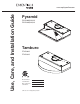
Use, Care, and Installation Guide www.zephyronline.com Pyramid ZPY-E30AB, AW, AS ZPY-E36AB, AW, AS Tamburo ZTA-E30AS ZTA-E36AS Model number: Serial Number: Date of Purchase: Sales Dealer: JUN 08.
www.zephyronline.
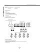
INSTALLATION Ductwork Calculation Sheet ................................... Mounting Height & Clearance................................ Ducting Options ........................................................... Speci cations ............................................................... Preparing Electrical .................................................... Preparing Ducting Location .................................... Recirculating .................................................................
www.zephyronline.com Important Safety Notice READ AND SAVE THESE INSTRUCTIONS WARNING TO REDUCE THE RISK OF FIRE OR ELECTRIC SHOCK, DO NOT USE THIS FAN WITH ANY SOLID-STATE CONTROL DEVICE. WARNING TO REDUCE THE RISK OF FIRE ELECTRIC SHOCK, OR INJURY TO PERSONS, OBSERVE THE FOLLOWING: a. Use this unit only in the manner intended by the manufacturer, if you have questions, contact the manufacturer. b.
TO REDUCE THE RISK OF FIRE, USE ONLY METAL DUCTWORK. CAUTION To reduce risk of re and to properly exhaust air outside - Do not vent exhaust air into spaces within walls, ceilings, attics, crawl spaces or garages. OPERATION Always leave safety grilles and lters in place. Without these components, operating blowers could catch onto hair, ngers and loose clothing.
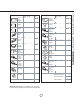
List of Materials www.zephyronline.
Equivalent number length x used = Duct pieces Total Total 3-1/ 4” x 10” 1 Ft. Rect., straight x( ) = Ft. 6” Round 30 Ft. wall cap with damper x( ) = Ft. 6” Round, straight 1 Ft. x( ) = Ft. 6” Round, roof cap x( ) = Ft. 7”-10” Round, 1 Ft. x( ) = Ft. 6” round to 1 Ft. 3-1/ 4” x 10” rect. transition x( ) = Ft. 3-1/ 4” x 10” 15 Ft. Rect.90 0 elbow x( ) = Ft. x( ) = Ft. 3-1/ 4” x 10” 9 Ft. Rect.45 0 elbow x( ) = Ft. 6” round to 16 Ft. 3-1/ 4” x 10” rect.
Installation – Mounting Height & Clearance www.zephyronline.com Minimum mounting height between range top to hood bottom should be no less than 24”. Maximum mounting height should be no higher than 32”. It is important to install the hood at the proper mounting height. Hoods mounted too low could result in heat damage and re hazard; while hoods mounted too high will be hard to reach and will lose its performance and ef ciency.
NEVER exhaust air or terminate duct work into spaces between walls, crawl spaces, ceiling, attics or garages. All exhaust must be ducted to the outside. Use metal ductwork only. Fasten all connections with sheet metal screws and tape all joints with certi ed Silver Tape or Duct Tape.
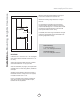
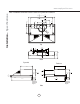
www.zephyronline.com Installation – Specifications Note: Installation dimensions are the same for Pyramid and Tamburo 2" 15 29 16 " 15 or 35 16 " 3 25 16 " 1 or 31 8 " 11 8 16 " 15 9 16 " 1" 5 1 48" 34" 1 15 " 16 elec. k/o 8" 6 1 16 5 " CL Top 3 1 16 " 15 9 16 " 11 8 16 " 7 16" 1 34" elec. k/o 3 78" CL Back Pyramid Tamburo 12" 12" " 1" 8 1 . 10 4 4 9 1 16 " 3 4 4" " 1" 8 1 .
WARNING All Electrical work must by performed by qualified electrician or person with similar technical knowledge and background. For personal safety, remove house fuse or open circuit breaker before beginning installation. Do not use extension cord or adapter plug with this appliance. Follow national electrical codes or prevailing local codes and ordinances.
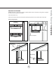
Installation – Preparing Duct Location www.zephyronline.com Note: If using hood in recirculating mode skip these steps and turn to page 11. 1 Vertical Ducting (7" Round) 6 2 5 3 1. Using a at-head screwdriver, remove both the rectangular and round knock-out plates located on top of hood 4 2. Secure 7" round collar to top of hood using (6) M4 x 8 screws. 3 4 5 2 Vertical Ducting 6 1 (3-1/4"x10" Rectangular) 1.
rocker switch For Tamburo (ZTA) only: Unscrew and remove the front cover front slot 1. Change rocker switch position from I to 0. Rocker switch is located on electrical box to the right of motor housing. charcoal lter bracket charcoal lter bracket center panel back slot metal air diverter plate 2. Remove air diverter plate slot covers. Remove metal air diverter plate from front slot and re-position to back slot. Re-install air diverter plate covers. 3.
Installation – Optional Utensil Bar www.zephyronline.com Note: Utensil bar is designed for use when hood is installed under a 12" deep cabinet. There are 3 height options for installing the utensil bar. Install utensil bar and adjust the height before mounting the hood. Utensil bar should press against the wall when hood is installed. S-Hooks Fig 1 1. Secure utensil bar to back of hood using (2) M4 x 8 utensil bar screws 12 Fig 2 2. Install optional s hooks used to hang utensils.
8. Electrical 1. Select preferred duct location (vertical or horizontal) if ducting out of kitchen. Refer to page 10 for details. 6. Duct opening/ cutout 2. Install utensil bar to hood. Refer to page 12 for details. 3. Begin installation by removing the mesh lters. 9. Aluminum duc tape 4. Reinforce cabinet with 1”x2” wood strips if additional strengthening is required or if cabinets are framed. 4. Add 1”x2” wood strips 5. Temporarily position the range hood in the desired mounting location.
Controls – Slide Controls www.zephyronline.com 1 Blower On/Off Speed Selection III II I 2 Lights Off/Bright/Dim II 0 1 BLOWER ON/OFF/SPEED SELECTION 0 is off, I is low speed, II is medium speed and III is high speed. 2 LIGHTS OFF/BRIGHT/DIM 0 is off, I is bright, and II is dim.
Clean periodically with hot soapy water and clean cotton cloth. Do not use corrosive or abrasive detergent, or steel wool/scouring pads which will scratch and damage surface. Do not use products containing chlorine bleach or orange cleaners. For heavier soil use liquid degreaser. After cleaning, you may use non-abrasive stainless steel polish/ cleaners, to polish and buff out the stainless luster and grain. Always scrub lightly using a micro ber or clean cotton cloth and with grain.
Maintenance – Lights www.zephyronline.com REPLACING LIGHT BULBS CAUTION: Light bulb becomes extremely hot when turned on. DO NOT touch bulb until switched off and cooled. Touching hot bulbs could cause serious burns. Make sure all power is turned off and bulbs are not hot. Remove by turning bulb counter clockwise. Note: Bulb does not unscrew; it turns 60 degrees, stops and falls out.
Issue Cause After installation, the unit doesn’t work. 1. The power source is not turned ON. 2. 3. 4. Light works, but motor is not turning. The unit is vibrating. The motor is working, but the lights are not. The hood is not venting out properly. Metal lter is vibrating. Metal lter is vibrating. 5. 1. 2. 3. 1. 2. 3. 1. 2. What to do 1. Make sure the circuit breaker and the unit’s power is ON. The power line and the cable locking connector is 2.
List of Parts and Accessories www.zephyronline.com DESCRIPTION PART # Replacement Parts Light Bulb MR16 (GU10) 50W (each) Mesh Filter, All Models (each) Z0B-0020S 50200030 Optional Accessories Recirculating Kit, All Models Charcoal Filter Replacement (each) ZRC-0200 Z0F-C002 To order parts, visit us online at http://store.zephyronline.com or call us at 1.888.880.
STAPLE YOUR RECEIPT HERE Proof of the original purchase date is needed to obtain service under warranty Limited Warranty TO OBTAIN SERVICE UNDER WARRANTY OR FOR ANY SERVICE RELATED QUESTIONS, please call: 1-888-880-8368 Zephyr Corporation (referred to herein as “we” or “us”) warrants to the original consumer purchaser (referred to herein as “you” or “your”) of Zephyr products (the “Products”) that such Products will be free from defects in materials or workmanship as follows: Two Year Limited Warranty f