Installation and Operating Instructions ® Zip Hydroboil Electronic Large boiling water 211061 211062 212061 212062 204061 204062 Hydroboil HBE6 15L S/S Hydroboil HBE6 15L White Hydroboil HBE6 25L S/S Hydroboil HBE6 25L White Hydroboil HBE6 40L S/S Hydroboil HBE6 40L White Zip Hydroboil Electronic - Installation & Operating Instructions - 89956 - Feb 2013 v1.
This page intentionally left blank Page 2 of 16 Zip Hydroboil Electronic - Installation & Operating Instructions - 89956 - Feb 2013 v1.
Contents Read these warnings first . . . . . . . . . . . . . . . 4 Installation Requirements . . . . . . . . . . . . . . . 4 , 5 Installation Procedures . . . . . . . . . . . . . . . . . 5 - 7 Step 1 – Positioning . . . . . . . . . . . . . . . 5 Step 2 – Fastening . . . . . . . . . . . . . . . . 5 See page 6, Wall Mounting Template Dimensions Step 3 – Connecting . . . . . . . . . . . . . . . 6 a) Plumbing. . . . . . . . . . . . . . . . 6 b) Venting . . . . . . . . . . . . . . . . . 6 , 7 c) Electrical . .
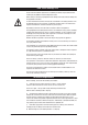
Read These Warnings First Please read all installation requirements, installation procedures and precautions before installing any Zip Hydroboil instant boiling water heater. Never attempt to install any Zip Hydroboil instant boiling water heater without reading all of the applicable instructions. In some hard water areas where mineral scale accumulation in the boiling chamber of the Zip Hydroboil may become a problem, consideration should be given to the maintenance required.
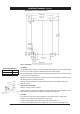
Installation Requirements (continued) e) Access to drainage from a vent situated at the base of the heater. f) In all installation instances the walls of the heater must be vertical and the base horizontal, there can be no exceptions to this rule. Note: If the water pressure is likely to exceed 700 kpa, a 350 kpa pressure reducing valve must be installed in the cold water supply line.
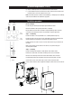
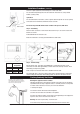
Installation Procedures (continued) Wall template for 15, 25 & 40 litre models 374 (15L, 25L) 499 (40L) 295 (15L, 25L) 420 (40L) 591 (15L) 771 (25L) 831 (40L) 188 (15L, 25L) 313 (40L) Step 3 – Connecting a) Plumbing Aprox weight when filled 15 Litre models 25 Litre models 40 Litre models For exposed plumbing connection, connect the cold water inlet pipe from the base of the heater directly to the 15 mm or half-inch compression fittings with the nuts and olives provided. 34.
Installation Procedures (continued) more than 3 right angle bends, and discharges to a waste water drain. For concealed vent plumbing, direct the vent outlet from the heater rear, using a visible tundish. (see diag at left) c) Electrical For concealed electrical connection, connect a power cable through the rear access opening of the heater to the terminal block within the heater as shown. Vent line Visible Tundish Do not turn the power ON until the heater is filled to the tap level, with water.
Tap Operating Procedures Tap Operation Safety feature. Zip Hydroboil has a unique safety device designed to reduce the incidence of accidental operation of the tap.
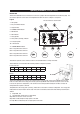
Operating Procedures (setting the controls) DESCRIPTION The Electronic Hydroboil has user interface that consists of a graphic LCD and 4 Capacitive Sensor Switches, (CSS). The user interface gives the current status of the Hydroboil and allows the user to configure it as required. Legend: The user interface is shown below.
Default settings When the unit actually enters energy saver mode it is indicated by the Sleep Mode Indicator on the LCD. In 2 Hour Sleep Mode, if there has been no water drawn through the tap or no touches of the capacitive switch sensors for two hours, the temperature of the water in the tank will be allowed to drop to and be maintained at 65ºC. (The time taken for the water temperature to drop to 65ºC can be as much as 12 hours depending on ambient conditions and other external factors).
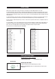
Setting operational modes (continued) Configuration mode The Default configuration for the Hydroboil is as follows. tting operational modes Setpoint display To enter Configuration Mode, press and hold the CSS1 and CSS4 for 10 seconds. The unit enters Configuration Mode and the user can configure the clock as follows. SET SETPOINT To return to Normal Mode, press CSS4. To increment the setpoint, press either CSS2 or CSS3. To step to the next configuration parameter, press CSS1.
Setting operational modes (continued) CONFIGURE SLEEP MODE perational modes Sleep display To return to Normal Mode, press CSS4. To configure sleep mode to kick in after 4 hours, press either CSS2 or CSS3. To step to the next configuration parameter, press CSS1. Note: Configuring Sleep Mode moves in a circular fashion. It goes from 2 hours to 4 hours to OFF and back to 2 hours etc. Low light display ENABLE LOW LIGHT SENSOR “Sleep-when-it’s-dark” feature. To return to Normal Operation, press CSS4.
Problem Solving Sympton Possible Cause Solution Fails to dispense water. Water isolating valve turned off. Blocked filter, blocked meter tube, blocked strainer, jammed ball valve assy, airlock in transfer tube. Incorrectly positioned outlet tube. Check water supply valve. Reposition silicon outlet tube in outlet nozzle. Contact Zip authorised agent. No power. Water not boiling. Runs out of boiling water and fails to refill. Outlet tap drips. Overflow from vent. Excessive steam from vent.
Spare Parts Page 14 of 16 Key Kit No.
Spare Parts &RQQHFWRU 21/< Contactor Only for 40L IRU / '(7$,/ &RQQHFWRU 6&$/( Page 15 of 16 Zip Hydroboil Electronic - Installation & Operating Instructions - 89956 - Feb 2013 v1.
Contact Details Head Office Zip Heaters (Aust) Pty. Ltd. ABN 46 000 578 727 67 Allingham Street Condell Park NSW 2200 Postal: Locked Bag 80 Bankstown 1885 Australia WMKA00099 AS 3498 Website: www.zipheaters.com Facsimile (02) 9796 3858 Telephone (02) 9796 3100 Free Call 1 800 638 633 As Zip policy is one of continuous product improvement, changes to specifications may be made without prior notice. Images in this booklet have been modified and may not be true representations of the finished goods.