
Operating instructions


Page 5 of 16 Zip Hydroboil Electronic - Installation & Operating Instructions - 89956 - Feb 2013 v1.07
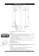
40 Litre ONLY
e) Access to drainage from a vent situated at the base of the heater.
f) In all installation instances the walls of the heater must be vertical and the base
horizontal, there can be no exceptions to this rule.
Note: If the water pressure is likely to exceed 700 kpa, a 350 kpa pressure reducing
valve must be installed in the cold water supply line.
Before You Begin
Locate the paper mounting-hole template packed with the heater.
Read the installation and operating instructions completely.
Decide whether to install with concealed or exposed plumbing and/or electrical
connections. Concealed connections are preferred for superior appearance.
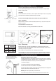
Step 1 – Positioning
Position the heater so the tap will drain on to a draining board or drip tray.
Position the base of the tap to be not less than 200 mm above the draining board
(height should be increased only if essential for filling larger vessels).
Provide clearance for service access of not less than 150 mm top, 65 mm left, 20
mm right.
Mark corner positions for the heater on the wall so as to position the paper
mounting-hole template.
Step 2 – Fastening
Position mounting-hole template on wall and drill holes where shown.
Drill holes for water inlet, vent outlet and wiring if rear access is intended.
Remove cover fastening screws from heater and lift whole cover off heater.
Install plumbing and wiring and prepare pipe ends and wiring ends as shown.
Screw heater chassis to the wall using screws or bolts suited to the wall.
Screws or bolts must be able to support the weight as shown in the chart on the left.
Installation Requirements
(continued)
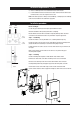
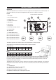
Installation procedure
COLD
INLET
VENT
OUTLET
INLET
POSITION
VENT
POSITION
45mm
Elbow