Motherboard P8P67 Deluxe
E6306 Third Edition (V3) January 2011 Copyright © 2011 ASUSTeK COMPUTER INC. All Rights Reserved. No part of this manual, including the products and software described in it, may be reproduced, transmitted, transcribed, stored in a retrieval system, or translated into any language in any form or by any means, except documentation kept by the purchaser for backup purposes, without the express written permission of ASUSTeK COMPUTER INC. (“ASUS”).
Contents Notices ........................................................................................................................ vi Safety information...................................................................................................... vii About this guide........................................................................................................ viii P8P67 Deluxe specifications summary......................................................................
Contents Chapter 3: 3.1 3.2 3.3 3.4 3.5 BIOS setup program................................................................................... 3-1 3.2.1 3.2.2 Advanced menu........................................................................................ 3-13 3.5.1 CPU Configuration..................................................................... 3-14 3.5.3 PCH Configuration..................................................................... 3-16 3.5.5 3.5.6 3.8 3.5.7 3.10 APM........
Contents 4.3.5 EPU............................................................................................ 4-10 4.3.7 Probe II...................................................................................... 4-12 4.3.6 4.4 FAN Xpert.................................................................................. 4-11 4.3.8 Audio configurations.................................................................. 4-13 RAID configurations.........................................................
Notices Federal Communications Commission Statement This device complies with Part 15 of the FCC Rules. Operation is subject to the following two conditions: • • This device may not cause harmful interference, and This device must accept any interference received including interference that may cause undesired operation. This equipment has been tested and found to comply with the limits for a Class B digital device, pursuant to Part 15 of the FCC Rules.
Safety information Electrical safety • • • • • • To prevent electrical shock hazard, disconnect the power cable from the electrical outlet before relocating the system. When adding or removing devices to or from the system, ensure that the power cables for the devices are unplugged before the signal cables are connected. If possible, disconnect all power cables from the existing system before you add a device.
About this guide This user guide contains the information you need when installing and configuring the motherboard. How this guide is organized This guide contains the following parts: • • • • • Chapter 1: Product introduction This chapter describes the features of the motherboard and the new technology it supports. Chapter 2: Hardware information This chapter lists the hardware setup procedures that you have to perform when installing system components.
Conventions used in this guide To ensure that you perform certain tasks properly, take note of the following symbols used throughout this manual. DANGER/WARNING: Information to prevent injury to yourself when trying to complete a task. CAUTION: Information to prevent damage to the components when trying to complete a task. IMPORTANT: Instructions that you MUST follow to complete a task. NOTE: Tips and additional information to help you complete a task.
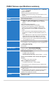
P8P67 Deluxe specifications summary CPU LGA1155 socket for Intel® 2nd Generation Core™ i7 / ���������� Core™ i5 / Core™ i3 ���������� Processors Supports 32nm CPU Supports Intel® Turbo Boost Technology 2.0 * The Intel® Turbo Boost Technology 2.0 support depends on the CPU types. ** Refer to www.asus.com for Intel CPU support list Chipset Intel® P67 Express Chipset Memory 4 x DIMM, max. 32GB*, DDR3 2200(O.C.)** / 2133(O.C.) / 1866(O.C.
P8P67 Deluxe specifications summary Audio Realtek® ALC889 8-channel High Definition Audio CODEC - Absolute Pitch 192khz/24bit True BD Lossless Sound - BD Audio Layer Content Protection - DTS Surround Sensation UltraPC - Supports Jack-Detection, Multi-Streaming and Front Panel Jack-Retasking - Coaxial / Optical S/PDIF Out ports at back I/O IEEE 1394 VIA® 6315N controller supports 2 x IEEE 1394a ports (one at midboard, one at back panel) USB 2 x NEC® USB 3.0 controllers - 2 x USB 3.
P8P67 Deluxe specifications summary ASUS exclusive overclocking features Precision Tweaker 2: - vCore: Adjustable CPU voltage at 0.005V increment - vCCIO: Adjustable I/O voltage at 0.00625V increment - vCCSA: 144-step system agent voltage control - vDRAM Bus: 160-step Memory voltage control - vPCH: 90-step Chipset voltage control - vCPU PLL: 160-step CPU & PCH PLL voltage control SFS (Stepless Frequency Selection): - BCLK/PEG frequency tuning from 80MHz up to 300MHz at 0.
Chapter 1 Chapter 1: Product introduction 1.1 Welcome! Thank you for buying an ASUS® P8P67 Deluxe motherboard! Chapter 1 The motherboard delivers a host of new features and latest technologies, making it another standout in the long line of ASUS quality motherboards! Before you start installing the motherboard, and hardware devices on it, check the items in your package with the list below. 1.2 Package contents Check your motherboard package for the following items.
1.3 Special features 1.3.1 Product highlights Chapter 1 LGA1155 socket for Intel® Second Generation Core™ i7 / Core™ i5 / Core™ i3 Processors This motherboard supports the Intel® second generation Core™ i7 / Core™ i5 / Core™ i3 processors in LGA1155 package with memory and PCI Express controllers integrated to support 2-channel (4 DIMMs) DDR3 memory and 16 PCI Express 2.0 lanes. This provides great graphics performance.
1.3.2 Dual Intelligent Processors 2 with DIGI+ VRM Chapter 1 The world’s first Dual Intelligent Processors from ASUS pioneered the use of two onboard chips—EPU (Energy Processing Unit) and TPU (TurboV Processing Unit). New generation Dual Intelligent Processors 2 with DIGI+ VRM digital power design launch control into a new era, empowering users with superior flexibility and perfect precision to ensure optimized performance, extreme system stability and greater power efficiency.
MemOK! Chapter 1 MemOK! quickly ensures memory boot compatibility. This remarkable memory rescue tool requires a mere push of a button to patch memory issues. MemOK! determines failsafe settings and dramatically improves your system boot success. AI Suite II With its user-friendly interface, ASUS AI Suite II consolidates all the exclusive ASUS features into one simple to use software package.
ASUS Q-Shield Chapter 1 The specially designed ASUS Q-Shield does without the usual "fingers" - making it convenient and easy to install. With better electric conductivity, it ideally protects your motherboard against static electricity and shields it against Electronic Magnetic Interference (EMI). ASUS Q-Connector ASUS Q-Connector allows you to easily connect or disconnect the chassis front panel cables to the motherboard.
Chapter 1 1-6 Chapter 1: Product Introduction
Chapter 2 Chapter 2: Hardware information 2.1 Before you proceed Take note of the following precautions before you install motherboard components or change any motherboard settings. • Unplug the power cord from the wall socket before touching any component. • Before handling components, use a grounded wrist strap or touch a safely grounded object or a metal object, such as the power supply case, to avoid damaging them due to static electricity.
2.2 Motherboard overview 2.2.1 Motherboard layout Chapter 2 Refer to 2.2.7 Internal connectors and 2.3.10 Rear panel connection for more information about rear panel connectors and internal connectors.
Connectors/Jumpers/Slots Page 1. ATX power connectors (24-pin EATXPWR, 8-pin EATX12V) 2-31 2. LGA1155 CPU socket 2-4 3. CPU, chassis, and power fan connectors (4-pin CPU_FAN, 4-pin CHA_FAN1, 3-pin CHA_FAN2, 3-pin PWR_FAN1–2) 2-30 4. DDR3 DIMM slots 2-5 5. TPU switch 2-17 6. MemOK! switch 2-17 7. USB 3.0 connector (20-1 pin USB3_34) 2-28 8. Marvell Serial ATA 6.0 Gb/s connectors (7-pin SATA6G_E1/E2 [navy blue]) 2-27 ® 9. Intel® P67 Serial ATA 6.
2.2.2 Central Processing Unit (CPU) The motherboard comes with a surface mount LGA1155 socket designed for the Intel® 2nd Generation Core™ i7 / Core™ i5 / Core™ i3 Processors. Chapter 2 Ensure that all power cables are unplugged before installing the CPU. 2-4 • The LGA1156 CPU is incompatible with the LGA1155 socket. DO NOT install a LGA1156 CPU on the LGA1155 socket. • Upon purchase of the motherboard, ensure that the PnP cap is on the socket and the socket contacts are not bent.
2.2.3 System memory The motherboard comes with four Double Data Rate 3 (DDR3) Dual Inline Memory Modules (DIMM) slots. Chapter 2 A DDR3 module is notched differently from a DDR or DDR2 module. DO NOT install a DDR or DDR2 memory module to the DDR3 slot.
Memory configurations You may install 1GB, 2GB and 4GB unbuffered and non‑ECC DDR3 DIMMs into the DIMM sockets. Chapter 2 • You may install varying memory sizes in Channel A and Channel B. The system maps the total size of the lower-sized channel for the dual-channel configuration. Any excess memory from the higher-sized channel is then mapped for single-channel operation. • Due to CPU behavior, DDR3 2200/2000/1800 MHz memory module will run at DDR3 2133/1866/1600 MHz frequency as default.
P8P67 Deluxe Motherboard Qualified Vendors Lists (QVL) DDR3 2133(O.C.) MHz capability Vendor Part No. Size SS/ DS Chip Brand Chip NO. Timing Voltage DIMM socket support (Optional) G.SKILL F3-17600CL9D-4GBTDS(XMP) 4GB(2 x 2GB) DS - - 1.65 • 9-9-9-24 1 DIMM 2 DIMM 4 DIMM • * The above QVL is for the DDR3 2200 MHz memory module. Due to CPU behavior, DDR3 2200 MHz memory module will run at DDR3 2133 MHz frequency. Chip NO.
P8P67 Deluxe Motherboard Qualified Vendors Lists (QVL) DDR3 1600 MHz capability Vendor Part No. Size SS/ DS Chip Brand Chip NO. Timing Voltage DIMM socket support (Optional) G.SKILL F3-14400CL6D-4GBFLS(XMP) 4GB(2 x 2GB) DS - - 6-8-6-24 1.65 • • KINGSTON KHX1800C9D3T1K3/6GX(XMP) 6GB(3 x 2GB) DS - - - 1.65 • • G.SKILL F3-14400CL9D-4GBRL(XMP) 4GB(2 x 2GB) DS - - 9-9-9-24 1 DIMM 2 DIMM 4 DIMM • 1.6 • • *T he above QVL is for the DDR3 1800 MHz memory module.
P8P67 Deluxe Motherboard Qualified Vendors Lists (QVL) DDR3 1600 MHz capability (continued) Size SS/ Chip DS Brand Chip NO. Timing Voltage DIMM socket support (Optional) Super Talent WB160UX6G8(XMP) 6GB(3 x 2GB) DS - - 8 - • • EK Memory 4GB(2 x 2GB) DS - - 9 - • • Part No.
P8P67 Deluxe Motherboard Qualified Vendors Lists (QVL) DDR3 1333 MHz capability (continued) Part No. Size SS/ Chip Brand Chip NO. DS Timing ELPIDA EBJ21UE8BDF0-DJ-F 2GB DS ELPIDA J1108BDSE-DJ-F - - • • • G.SKILL F3-10600CL8D-2GBHK 2GB(2 x 1GB) SS - - - 1.65 • • • G.SKILL F3-10666CL7D-4GBPI(XMP) 4GB(2 x 2GB) DS - - 7-7-7-21 1.5 • • • G.SKILL F3-10666CL8D4GBECO(XMP) 4GB(2 x 2GB) DS - - 8-8-8-24 1.
P8P67 Deluxe Motherboard Qualified Vendors Lists (QVL) DDR3 1333 MHz capability (continued) Part No. Size SS/ Chip Brand Chip NO.
P8P67 Deluxe Motherboard Qualified Vendors Lists (QVL) DDR3 1066 MHz capability Vendor Part No. Size SS/ Chip DS Brand Chip NO. Timing Crucial CT12864BA1067.8FF 1GB SS MICRON D9KPT 7 Crucial CT12872BA1067.9FF 1GB SS MICRON D9KPT(ECC) 7 Crucial Crucial Crucial Crucial ELPIDA ELPIDA ELPIDA ELPIDA ELPIDA GEIL Hynix Hynix Hynix Chapter 2 Hynix Kingston Kingston MICRON MICRON MICRON MICRON MICRON MICRON CT12864BA1067.8SFD CT25664BA1067.16FF CT25664BA1067.16SFD CT25672BA1067.
2.2.4 Expansion slots Chapter 2 Ensure to unplug the power cord before adding or removing expansion cards. Failure to do so may cause you physical injury and damage motherboard components. 1 2 3 ® 4 P8P67 DELUXE 5 6 7 RESET Slot No. Slot Description 1 PCIe 2.0 x1_1 slot 3 PCIe 2.0 x1_2 slot 2 4 5 6 7 PCIe 2.0 x16_1 slot (single at x16 or dual at x8/x8 mode) PCI slot 1 PCIe 2.0 x16_2 slot (at x8 mode) PCI slot 2 PCIe 2.
• • • • In single VGA card mode, use the PCIe 2.0 x16_1 slot (navy blue) for a PCI Express x16 graphics card to get better performance. In CrossFireX™ or SLI™ mode, use the PCIe 2.0 x16_1 and PCIe 2.0 x16_2 slots for PCI Express x16 graphics cards to get better performance. We recommend that you provide sufficient power when running CrossFireX™ or SLI™ mode. Refer to page 2-31 for details.
2.2.5 Onboard switches Onboard switches allow you to fine-tune performance when working on a bare or opencase system. This is ideal for overclockers and gamers who continually change settings to enhance system performance. Power-on switch The motherboard comes with a power-on switch that allows you to power up or wake up the system.
3. Chapter 2 2-16 MemOK! switch Installing DIMMs that are incompatible with the motherboard may cause system boot failure, and the DRAM_LED near the MemOK! switch lights continuously. Press and hold the MemOK! switch until the DRAM_LED starts blinking to begin automatic memory compatibility tuning for successful boot. • Refer to section 2.2.6 Onboard LEDs for the exact location of the DRAM_LED. • The DRAM_LED also lights when the DIMM is not properly installed.
4. TPU switch Turning this switch to Enable will automatically optimize the system for fast, yet stable clock speeds. Chapter 2 For ensuring the system performance, turn the switch setting to Enable when the system is powered off. • The TPU LED (O2LED1) near the TPU switch lights when the switch setting is turned to Enable. Refer to section 2.2.6 Onboard LEDs for the exact location of the TPU LED.
5. EPU switch Turning this switch to Enable will automatically detect the current PC loadings and intelligently moderate the power consumption. For ensuring the system performance, turn the switch setting to Enable when the system is powered off. Chapter 2 2-18 • The EPU LED (O2LED2) near the EPU switch lights when the switch setting is turned to Enable. Refer to section 2.2.6 Onboard LEDs for the exact location of the EPU LED.
2.2.6 POST State LEDs The POST State LEDs of CPU, DRAM, VGA card, and HDD indicate key components status during POST (Power-on Self Test). If an error is found , the LED next to the error device will continue lighting until the problem is solved. This user-friendly design provides an intuitional way to locate the root problem within a second. Chapter 2 1. Onboard LEDs 2. ID LEDs The ID LEDs provide an elegant embellishment to the motherboard design.
3. Chapter 2 4. 2-20 TPU LED The TPU LED lights when the TPU switch is turned to Enable. EPU LED The EPU LED lights when the EPU switch is turned to Enable.
Q-Code LEDs The Q-Code LED design provides you the 2-digit display, allowing you to know the system status. Refer to the Q-Code table below for details. Chapter 2 5. Q-Code table Code 00 01 02 03 04 05 06 07 08 09 0A 0B 0C – 0D 0E 0F 10 11 – 14 15 – 18 19 – 1C 1D – 2A 2B – 2F 30 Description Not used Power on. Reset type detection (soft/hard).
Q-Code table (continued) Code 31 32 – 36 37 – 3A 3B – 3E 3F – 4E 4F 50 – 53 Chapter 2 54 55 56 57 58 59 5A 5B 5C – 5F E0 E1 E2 E3 E4 – E7 E8 E9 EA EB EC – EF F0 F1 F2 F3 F4 F5 – F7 F8 F9 FA FB – FF 60 61 62 2-22 Description Memory Installed CPU post-memory initialization Post-Memory System Agent initialization is started Post-Memory PCH initialization is started OEM post memory initialization codes DXE IPL is started Memory initialization error.
Q-Code table (continued) Description CPU DXE initialization is started PCI host bridge initialization System Agent DXE initialization is started System Agent DXE SMM initialization is started System Agent DXE initialization (System Agent module specific) PCH DXE initialization is started PCH DXE SMM initialization is started PCH devices initialization PCH DXE Initialization (PCH module specific) ACPI module initialization CSM initialization Reserved for future AMI DXE codes OEM DXE initialization codes Boo
Q-Code table (continued) Chapter 2 Code AC AD AE AF B0 B1 B2 B3 B4 B5 B6 B7 B8– BF C0– CF D0 D1 D2 D3 D4 D5 D6 D7 D8 D9 DA DB DC Description Reserved for ASL (see ASL Status Codes section below) Ready To Boot event Legacy Boot event Exit Boot Services event Runtime Set Virtual Address MAP Begin Runtime Set Virtual Address MAP End Legacy Option ROM Initialization System Reset USB hot plug PCI bus hot plug Clean-up of NVRAM Configuration Reset (reset of NVRAM settings) Reserved for future AMI codes OEM BDS
2.2.7 1. Internal connectors Intel P67 Serial ATA 6.0 Gb/s connectors (7-pin SATA6G_1/2 [gray]) ® These connectors connect to Serial ATA 6.0 Gb/s hard disk drives via Serial ATA 6.0 Gb/s signal cables. Chapter 2 If you installed Serial ATA hard disk drives, you can create a RAID 0, 1, 5, and 10 configuration with the Intel® Rapid Storage Technology through the onboard Intel® P67 chipset. • These connectors are set to [AHCI Mode] by default.
2. Intel® P67 Serial ATA 3.0 Gb/s connectors (7-pin SATA3G_3–6 [blue]) These connectors connect to Serial ATA 3.0 Gb/s hard disk drives and optical disc drives via Serial ATA 3.0 Gb/s signal cables. If you installed Serial ATA hard disk drives, you can create a RAID 0, 1, 5, and 10 configuration with the Intel® Rapid Storage Technology through the onboard Intel® P67 chipset. Chapter 2 • These connectors are set to [AHCI Mode] by default.
Marvell® Serial ATA 6.0 Gb/s connectors (7-pin SATA6G_E1/E2 [navy blue]) These connectors connect to Serial ATA 6.0 Gb/s hard disk drives via Serial ATA 6.0 Gb/s signal cables. • The SATA6G_E1/E2 (navy blue) connectors are for data drives only. ATAPI device is not supported. • You must install Windows® XP Service Pack 3 or later versions before using Serial ATA hard disk drives. • When using NCQ, set the Marvell Storage Controller item in the BIOS to [Enabled]. Refer to section 3.5.
4. USB 3.0 connector (20-1 pin USB3_34) This connector is for the additional USB 3.0 ports, and complies with the USB 3.0 specificaton that supports up to 480 MBps connection speed. If the USB 3.0 front panel cable is available from your system chassis, with this USB 3.0 connector, you can have a front panel USB 3.0 solution. Chapter 2 You can connect the ASUS front panel USB 3.0 box to this connector to obtain the front panel USB 3.0 solution. 5. USB 2.
IEEE 1394a port connector (10-1 pin IE1394_2) This connector is for an IEEE 1394a port. Connect the IEEE 1394a module cable to this connector, then install the module to a slot opening at the back of the system chassis. Chapter 2 6. Never connect a USB cable to the IEEE 1394a connector. Doing so will damage the motherboard! The IEEE 1394 bracket is purchased separately. 7. Digital audio connector (4-1 pin SPDIF_OUT) This connector is for an additional Sony/Philips Digital Interface (S/PDIF) port(s).
8. CPU, chassis, and power fan connectors (4-pin CPU_FAN; 4-pin CHA_FAN1; 3-pin CHA_FAN2; 3-pin PWR_FAN1/2) Connect the fan cables to the fan connectors on the motherboard, ensuring that the black wire of each cable matches the ground pin of the connector. Chapter 2 Do not forget to connect the fan cables to the fan connectors. Insufficient air flow inside the system may damage the motherboard components.
Front panel audio connector (10-1 pin AAFP) This connector is for a chassis-mounted front panel audio I/O module that supports either HD Audio or legacy AC`97 audio standard. Connect one end of the front panel audio I/O module cable to this connector. • Chapter 2 9. We recommend that you connect a high-definition front panel audio module to this connector to avail of the motherboard’s high-definition audio capability.
• For a fully configured system, we recommend that you use a power supply unit (PSU) that complies with ATX 12 V Specification 2.0 (or later version) and provides a minimum power of 350 W. • Do not forget to connect the 4-pin/8-pin EATX12 V power plug; otherwise, the system will not boot. • Use of a PSU with a higher power output is recommended when configuring a system with more power-consuming devices. The system may become unstable or may not boot up if the power is inadequate.
11. System panel connector (20-8 pin PANEL) • • • • • Chapter 2 This connector supports several chassis-mounted functions. System power LED (2-pin PLED) This 2-pin connector is for the system power LED. Connect the chassis power LED cable to this connector. The system power LED lights up when you turn on the system power, and blinks when the system is in sleep mode. Hard disk drive activity LED (2-pin IDE_LED) This 2-pin connector is for the HDD Activity LED.
2.3 Building your computer system 2.3.1 Additional tools and components to build a PC system Chapter 2 1 bag of screws Philips (cross) screwdriver PC chassis Power supply unit Intel LGA 1155 CPU Intel LGA 1155 compatible CPU Fan DIMM SATA hard disk drive SATA optical disc drive (optional) Graphics card (optional) The tools and components in the table above are not included in the motherboard package.
2.3.2 CPU installation The LGA1156 CPU is incompatible with the LGA1155 socket. DO NOT install a LGA1156 CPU on the LGA1155 socket.
4 Chapter 2 5 C A B 6 2-36 Chapter 2: Hardware information
2.3.3 CPU heatsink and fan assembly installation Apply the Thermal Interface Material to the CPU heatsink and CPU before you install the heatsink and fan if necessary.
To uninstall the CPU heatsink and fan assembly 1 Chapter 2 2 A B B A 2-38 Chapter 2: Hardware information
2.3.
2.3.5 Motherboard installation The diagrams in this section are for reference only. The motherboard layout may vary with models, but the installation steps remain the same.
Chapter 2 3 DO NOT overtighten the screws! Doing so can damage the motherboard.
2.3.
2.3.
2.3.8 Front I/O Connector To install ASUS Q-Connector 1 2 IDE_LED+ IDE_LED- PWR Ground Chapter 2 Reset Ground IDE_LED R POWE SW RESET SW To install USB 2.0 Connector To install front panel audio connector AAFP USB 2.0 To install USB 3.0 Connector USB 3.
2.3.
2.3.10 Rear panel connection Chapter 2 Rear panel connectors 1. PS/2 keyboard/mouse combo port 9. 2. Coaxial S/PDIF Out port 10. External SATA port 3. USB 2.0 ports 5 and 6 11. Power External SATA port 4. Bluetooth module* 12. IEEE 1394a port 5. USB 2.0 ports 3 and 4 13. USB 2.0 ports 1 and 2 6. Realtek LAN (RJ-45) port** 14. USB 3.0 ports 1 and 2 ® Optical S/PDIF Out port 7. Intel® LAN (RJ-45) port** (Recommended for single LAN usage) 15. Clear CMOS switch 8. 16.
• Press the Clear CMOS switch to clear BIOS setup information only when the system hangs due to overclocking. • DO NOT insert a different connector to the external SATA port. • Due to USB 3.0 controller limitation, USB 3.0 devices can only be used under Windows® OS environment and after the USB 3.0 driver installation. • USB 3.0 devices can only be used as data storage only. • We strongly recommend that you connect USB 3.0 devices to USB 3.0 ports for faster and better performance for your USB 3.
2.3.11 Audio I/O connections Audio I/O ports Connect to Headphone and Mic Chapter 2 Connect to Stereo Speakers Connect to 2.
Connect to 4.1 channel Speakers Chapter 2 Connect to 5.1 channel Speakers Connect to 7.1 channel Speakers When the DTS Surround Sensation UltraPC function is enabled, ensure to connect the rear speaker to the gray port.
2.4 Starting up for the first time 1. After making all the connections, replace the system case cover. 3. Connect the power cord to the power connector at the back of the system chassis. 2. 4. 5. Be sure that all switches are off. Connect the power cord to a power outlet that is equipped with a surge protector. Turn on the devices in the following order: a. Monitor c. System power b. 6.
Chapter 3 Chapter 3: 3.1 Knowing BIOS BIOS setup The new ASUS EFI BIOS is an Extensible Firmware Interface that complies with uEFI architecture, offering a user-friendly interface that goes beyond traditional keyboard-only BIOS controls to enable more flexible and convenient mouse input. Users can easily navigate the new EFI BIOS with the same smoothness as their operating system. The term “BIOS” in this user manual refers to “EFI BIOS” unless otherwise specified.
3.2.1 EZ Mode By default, the EZ Mode screen appears when you enter the BIOS setup program. The EZ Mode provides you an overview of the basic system information, and allows you to select the display language, system performance mode and boot device priority. To access the Advanced Mode, click Exit/Advanced Mode, then select Advanced Mode. The default screen for entering the BIOS setup program can be changed. Refer to the Setup Mode item in section �������� 3.7 Boot memu for details.
3.2.2 Advanced Mode The Advanced Mode provides advanced options for experienced end-users to configure the BIOS settings. The figure below shows an example of the Advanced Mode. Refer to the following sections for the detailed configurations. To access the EZ Mode, click Exit, then select ASUS EZ Mode.
Menu items The highlighted item on the menu bar displays the specific items for that menu. For example, selecting Main shows the Main menu items. The other items (Ai Tweaker, Advanced, Monitor, Boot, Tool, and Exit) on the menu bar have their respective menu items. Back button This button appears when entering a submenu. Press or use the USB mouse to click this button to return to the previous menu screen.
3.3 Main menu The Main menu screen appears when you enter the Advanced Mode of the BIOS Setup program. The Main menu provides you an overview of the basic system information, and allows you to set the system date, time, language, and security settings. EFI BIOS Utility - Advanced Mode Ai Tweaker Main Exit Advanced Monitor BIOS Information BIOS Version Build Date EC F/W Version ME Version 0239 x64 10/07/2010 MBECE-0014 7.0.0.1115 CPU Information Genuine Intel(R) CPU 0 @ 3.
Administrator Password If you have set an administrator password, we recommend that you enter the administrator password for accessing the system. Otherwise, you might be able to see or change only selected fields in the BIOS setup program. To set an administrator password: 1. Select the Administrator Password item and press . 3. Confirm the password when prompted. 2. From the Create New Password box, key in a password, then press . To change an administrator password: 1. 2. 3. 4.
3.4 Ai Tweaker menu The Ai Tweaker menu items allow you to configure overclocking-related items. Be cautious when changing the settings of the Ai Tweaker menu items. Incorrect field values can cause the system to malfunction. The configuration options for this section vary depending on the CPU and DIMM model you installed on the motherboard.
Ai Overclock Tuner [Auto] Allows you to select the CPU overclocking options to achieve the desired CPU internal frequency. Select any of these preset overclocking configuration options: [Auto] [Manual] [X.M.P.] Loads the optimal settings for the system. Allows you to individually set overclocking parameters. If you install memory modules supporting the eXtreme Memory Profile (X.M.P.) Technology, choose this item to set the profiles supported by your memory modules for optimizing the system performance.
CPU Power Management The sub-items in this menu allow you to set the CPU ratio and features. CPU Ratio [Auto] Allows you to manually adjust the maximum non-turbo CPU ratio. Use <+> and <-> keys to adjust the value. The valid value ranges vary according to your CPU model. Enhanced Intel SpeedStep Technology [Enabled] Allows you to enable or disable the Enhanced Intel® SpeedStep Technology (EIST). [Disabled] Disables this function.
Additional Turbo Voltage [Auto] Use the <+> and <-> keys to adjust the value. Primary Plane Current Limit [Auto] Use the <+> and <-> keys to adjust the value with a 0.125A interval. DIGI+ VRM Load-Line Calibration [Auto] Load-line is defined by Intel VRM spec and affects CPU voltage. The CPU working voltage will decrease proportionally to CPU loading. Higher load-line calibration would get higher voltage and better overclocking performance, but increase the CPU and VRM thermal.
Duty Control [T.Probe] [T.Probe] [Extreme] Maintains the VRM thermal balance. Maintains the VRM current balance. CPU Current Capability [100%] This item provides wider total power range for overclocking. A higher value brings a wider total power range and extends the overclocking frequency range simultaneously. Configuration options: [100%] [110%] [120%] [130%] [140%] Do not remove the thermal module while changing the DIGI+ VRM related parrameters . The thermal conditions should be monitored.
VCCSA Voltage [Auto] Allows you to set the VCCSA voltage. The values range from 0.80V to 1.70V with a 0.00625V interval. VCCIO Voltage [Auto] Allows you to set the VCCIO voltage. The values range from 0.80V to 1.70V with a 0.00625V interval. CPU PLL Voltage [Auto] Allows you to set the CPU and PCH PLL voltage. The values range from 1.20V to 2.20V with a 0.00625V interval. PCH Voltage [Auto] Allows you to set the Platform Controller Hub voltage. The values range from 0.80V to 1.70V with a 0.
DRAM DATA REF Voltage on CHA/B [Auto] Allows you to set the DRAM DATA Reference Voltage on Channel A/B. The values range from 0.395x to 0.630x with a 0.005x interval. Different ratio might enhance DRAM overclocking ability. DRAM CTRL REF Voltage on CHA/B [Auto] Allows you to set the DRAM Control Reference Voltage on Channel A/B. The values range from 0.395x to 0.630x with a 0.005x interval. Different ratio might enhance DRAM overclocking ability.
3.5.1 CPU Configuration The items in this menu show the CPU-related information that the BIOS automatically detects. The items shown in this screen may be different due to the CPU you installed. EFI BIOS Utility - Advanced Mode Ai Tweaker Main Back Exit Advanced Monitor Boot Tool Advanced\ CPU Configuration > CPU Configuration Adjust Non-Turbo Ratio Genuine Intel(R) CPU 0 @ 3.
Hyper-threading [Enabled] The Intel Hyper-Threading Technology allows a hyper-threading processor to appear as two logical processors to the operating system, allowing the operating system to schedule two threads or processes simultaneously. [Enabled] [Disabled] Two threads per activated core are enabled. Only one thread per activated core is enabled. Active Processor Cores [All] Allows you to choose the number of CPU cores to activate in each processor package.
3.5.2 System Agent Configuration EFI BIOS Utility - Advanced Mode Ai Tweaker Main Back Exit Advanced Monitor Boot Tool Advanced\ System Agent Configuration > System Agent Configuration Initate Graphic Adapter PEG/PCI Select which graphics controller to use as the primary boot device. Initiate Graphic Adapter [PEG/PCI] Allows you to decide which graphics controller to use as the primary boot device. Configuration options: [PCI/PEG] [PEG/PCI] 3.5.
SATA Mode [AHCI Mode] Allows you to set the SATA configuration. [Disabled] [IDE Mode] [AHCI Mode] [RAID Mode] Disables the SATA function. Set to [IDE Mode] when you want to use the Serial ATA hard disk drives as Parallel ATA physical storage devices. Set to [AHCI Mode] when you want the SATA hard disk drives to use the AHCI (Advanced Host Controller Interface).
3.5.5 USB Configuration The items in this menu allow you to change the USB-related features. EFI BIOS Utility - Advanced Mode Ai Tweaker Main Back Advanced Exit Monitor Boot Tool Advanced\ USB Configuration > USB Configuration USB Devices: 1 Mouse Legacy USB Support Enabled Legacy USB3.0 Support Enabled EHCI Hand-off Disabled Enables Legacy USB support. AUTO option disables legacy support if no USB devices are connected.
3.5.6 Onboard Devices Configuration EFI BIOS Utility - Advanced Mode Ai Tweaker Main Back Exit Advanced Monitor Boot Tool Advanced\ Onboard Devices Configuration > HD Audio Controller Enabled Front Panel Type HD SPDIF Out Type SPDIF Renesas Electronics USB 3.
SPDIF Out Type [SPDIF] [SPDIF] [HDMI] Sets to [SPDIF] for SPDIF audio output. Sets to [HDMI] for HDMI audio output. Renesas Electronics USB 3.0 [Enabled] [Enabled] [Disabled] Enables the USB 3.0 controller. Disables the controller. VIA 1394 [Enabled] [Enabled] [Disabled] Enables the onboard IEEE 1394a controller. Disables the controller. Marvell Storage Controller [Enabled] Allows you to select the Marvell storage controller operating mode. [Disabled] [Enabled] Disables the controller.
Realtek LAN [Enabled] [Enabled] [Disabled] Enables the Realtek LAN controller. Disables the controller. Realtek PXE OPROM [Disabled] This item appears only when you set the previous item to [Enabled] and allows you to enable or disable the PXE OptionRom of the Realtek LAN controller. Configuration options: [Enabled] [Disabled] Intel LAN [Enabled] [Enabled] [Disabled] Enables the Intel LAN controller. Disables the controller.
3.5.7 APM EFI BIOS Utility - Advanced Mode Ai Tweaker Main Back Advanced Exit Monitor Boot Tool Advanced\ APM > Restore AC Power Loss Power Off Power On By PS/2 Keyboard Disabled Power On By PS/2 Mouse Disabled Power On By PCI Disabled Power On By PCIE Disabled Power On By Ring Disabled Power On By RTC Disabled Specify what state to go to when power is re-applied after a power failure (G3 state).
3.6 Monitor menu The Monitor menu displays the system temperature/power status, and allows you to change the fan settings.
CPU Q-Fan Control [Enabled] [Disabled] [Enabled] Disables the CPU Q-Fan control feature. Enables the CPU Q-Fan control feature. CPU Fan Speed Low Limit [600 RPM] This item appears only when you enable the CPU Q-Fan Control feature and allows you to disable or set the CPU fan warning speed.
Chassis Fan Profile [Standard] This item appears only when you enable the Chassis Q-Fan Control feature and allows you to set the appropriate performance level of the chassis fan. [Standard] Sets to [Standard] to make the chassis fan automatically adjust depending on the chassis temperature. [Silent] Sets to [Silent] to minimize the fan speed for quiet chassis fan operation. [Turbo] Sets to [Turbo] to achieve maximum chassis fan speed.
3.7 Boot menu The Boot menu items allow you to change the system boot options.
Boot Option Priorities These items specify the boot device priority sequence from the available devices. The number of device items that appears on the screen depends on the number of devices installed in the system. • • To select the boot device during system startup, press when ASUS Logo appears. To access Windows OS in Safe Mode, do any of the following: - Press when ASUS Logo appears. - Press after POST. Boot Override These items displays the available devices.
3.8.2 ASUS O.C. Profile This item allows you to store or load multiple BIOS settings. EFI BIOS Utility - Advanced Mode Ai Tweaker Main Back Exit Advanced Monitor Boot Tool Tool\ ASUS O.C. Profile > O.C.
3.8.3 ASUS Drive Xpert EFI BIOS Utility - Advanced Mode Ai Tweaker Main Back Advanced Exit Monitor Boot Tool Tool\ ASUS Drive Xpert > Drive Xpert Setup Utility Drive Xpert Mode Drive Xpert Mode Normal Mode Drive Xpert Device(s) List : > SATA 6G E1 (Navy Blue) > SATA 6G E2 (Navy Blue) • Before using the Drive Xpert function, ensure that you have connected the SATA signal cables and installed SATA hard disk drives to the SATA6G_E1 and SATA6G_E2 connectors.
3.9 Exit menu The Exit menu items allow you to load the optimal default values for the BIOS items, and save or discard your changes to the BIOS items. You can access the EZ Mode from the Exit menu. Exit Load Optimized Defaults Save Changes & Reset Discard Changes & Exit ASUS EZ Mode Launch EFI Shell from filesystem device Load Optimized Defaults This option allows you to load the default values for each of the parameters on the Setup menus.
3.10 Updating BIOS The ASUS website publishes the latest BIOS versions to provide enhancements on system stability, compatibility, or performance. However, BIOS updating is potentially risky. If there is no problem using the current version of BIOS, DO NOT manually update the BIOS. Inappropriate BIOS updating may result in the system’s failure to boot. Carefully follow the instructions of this chapter to update your BIOS if necessary. Visit the ASUS website (www.asus.
Updating the BIOS through the Internet To update the BIOS through the Internet: 1. From the ASUS Update screen, select Update BIOS from Internet, and then click Next. 2. Select the ASUS FTP site nearest you to avoid network traffic. If you want to enable the BIOS downgradable function and auto BIOS backup function, check the checkboxs before the two items on the screen. Select the BIOS version that you want to download. Click Next. 4.
Updating the BIOS through a BIOS file 1. From the ASUS Update screen, select Update BIOS from file, and then click Next. 2. Locate the BIOS file from the Open window, click Open, and click Next. 3. You can decide whether to change the BIOS boot logo. Click Yes if you want to change the boot logo or No to continue. 4. Chapter 3 To update the BIOS through a BIOS file: Follow the onscreen instructions to complete the update process. • The screenshots in this section are for reference only.
3.10.2 ASUS EZ Flash 2 utility The ASUS EZ Flash 2 feature allows you to update the BIOS without having to use a bootable floppy disk or an OS‑based utility. Before you start using this utility, download the latest BIOS from the ASUS website at www.asus.com. To update the BIOS using EZ Flash 2: 1. Insert the USB flash disk that contains the latest BIOS file to the USB port. 2. ������������������������������������������������������������� Enter the Advanced Mode of the BIOS setup program.
• This function can support devices such as a USB flash disk with FAT 32/16 format and single partition only. • DO NOT shut down or reset the system while updating the BIOS to prevent system boot failure! Ensure to load the BIOS default settings to ensure system compatibility and stability. Select the Load Optimized Defaults item under the Exit menu. See section 3.9 Exit Menu for details. 3.10.
3.10.4 ASUS BIOS Updater The ASUS BIOS Updater allows you to update BIOS in DOS environment. This utility also allows you to copy the current BIOS file that you can use as a backup when the BIOS fails or gets corrupted during the updating process. The succeeding utility screens are for reference only. The actual utility screen displays may not be same as shown. Before updating BIOS 1. 2. 3. Prepare the motherboard support DVD and a USB flash drive in FAT32/16 format and single partition.
Backing up the current BIOS To backup the current BIOS file using the BIOS Updater Ensure that the USB flash drive is not write-protected and has enough free space to save the file. 1. At the FreeDOS prompt, type bupdater /o[filename] and press . D:\>bupdater /oOLDBIOS1.rom Filename Extension The [filename] is any user-assigned filename with no more than eight alphanumeric characters for the filename and three alphanumeric characters for the extension. 2.
Updating the BIOS file To update the BIOS file using BIOS Updater 1. At the FreeDOS prompt, type bupdater /pc /g and press . D:\>bupdater /pc /g 2. The BIOS Updater screen appears as below. ASUSTek BIOS Updater for DOS V1.18 [2010/04/29] Current ROM BOARD: P8P67 DELUXE VER: 0204 DATE: 08/05/2010 Update ROM BOARD: Unknown VER: Unknown DATE: Unknown PATH: A:\ P8P67D.ROM A: 4194304 2010-08-05 17:30:48 Note [Enter] Select or Load [Up/Down/Home/End] Move 3.
Chapter 4 Chapter 4: 4.1 Software support Installing an operating system This motherboard supports Windows® XP/ 64-bit XP/ Vista / 64-bit ���������������������������� Vista / 7 / 64-bit 7� operating systems (OS). Always install the latest OS version and corresponding updates to maximize the features of your hardware. 4.2 • Motherboard settings and hardware options vary. Use the setup procedures presented in this chapter for reference only. Refer to your OS documentation for detailed information.
4.2.2 Obtaining the software manuals The software manuals are included in the support DVD. Follow the instructions below to get the necessary software manuals. The software manual files are in Portable Document Format (PDF). Install the Adobe® Acrobat® Reader from the Utilities menu before opening the files. 1. Click the Manual tab. Click ASUS Motherboard Utility Guide from the manual list on the left. 2. The Manual folder of the support DVD appears. Double-click the folder of your selected software.
4.3 Software information Most of the applications in the support DVD have wizards that will conveniently guide you through the installation. View the online help or readme file that came with the software application for more information. 4.3.1 AI Suite II AI Suite II is an all-in-one interface that integrates several ASUS utilities and allows users to launch and operate these utilities simultaneously. Installing AI Suite II To install AI Suite II on your computer 1. 2. 3.
4.3.2 DIGI+ VRM ASUS DIGI+ VRM allows you to adjust VRM voltage and frequency modulation to enhance reliability and stability. It also provides the highest power efficiency, generating less heat to longer component lifespan and minimize power loss. After installing AI Suite II from the motherboard support DVD, launch DIGI+ VRM by clicking Tool > DIGI+ VRM on the AI Suite II main menu bar. 4 1 2 Application helps 3 Apply all changes immediately 5 Undo all changes without applying Function no.
4.3.3 BT GO! BT GO! connects a bluetooth (BT) device with the motherboard through Bluetooth connection for file transferring, file synchronization, music playback, personal manager, and multiple remote functions. Launching BT GO! After installing AI Suite II from the motherboard support DVD, launch BT GO! by clicking Tool > BT GO! on the AI Suite II main menu bar.
4.3.4 TurboV EVO ASUS TurboV EVO introduces TurboV that allows you to manually adjust the CPU frequency and related voltages as well as Auto Tuning function that offers automatic and easy overlocking and system level up. After installing AI Suite II from the motherboard support DVD, launch TurboV EVO by clicking Tool > TurboV EVO on the AI Suite II main menu bar. Refer to the software manual in the support DVD or visit the ASUS website at www.asus.com for detailed software configuration.
Using Advanced Mode Click More Settings, and then click the Advanced Mode tab to adjust the advanced voltage settings. Advanced mode Target values Voltage Adjustment bars Undoes all changes without applying Applies all changes immediately Current values Click to restore all start-up settings CPU Ratio Allows you to manually adjust the CPU ratio.
4. Drag the adjustment bar upwards or downwards to the desired value. Adjustment bar • Set the CPU Ratio Setting item in BIOS to [Auto] before using the CPU Ratio function in TurboV. Refer to Chapter 3 of your motherboard user manual for details. • The CPU Ratio bars show the status of the CPU cores, which vary with your CPU model. Auto Tuning ASUS TurboV EVO includes two auto tuning modes, providing the most flexible auto-tuning options.
3. TurboV automatically overclocks the CPU, saves BIOS settings and restarts the system. After re-entering Windows, a message appears indicating auto tuning success. Click OK to exit. Using Extreme Tuning 2. Click the Auto Tuning tab and then click Extreme. Read through the warning messages and click OK to start auto-overclocking. 3. TurboV automatically overclocks the CPU and memory and restarts the system. After re-entering Windows, a message appears indicating the current overclocking result.
4.3.5 EPU EPU is an energy-efficient tool that satisfies different computing needs. This utility provides several modes that you can select to save system power. Selecting Auto mode will have the system shift modes automatically according to current system status. You can also customize each mode by configuring settings like CPU frequency, GPU frequency, vCore Voltage, and Fan Control.
4.3.6 FAN Xpert Fan Xpert intelligently allows you to adjust both the CPU and chassis fan speeds according to different ambient temperatures caused by different climate conditions in different geographic regions and your PC’s system loading. The built-in variety of useful profiles offer flexible controls of fan speed to achieve a quiet and cool environment.
4.3.7 Probe II Probe II is a utility that monitors the computer’s vital components, and detects and alerts you of any problem with these components. Probe II senses fan rotations, CPU temperature, and system voltages, among others. With this utility, you are assured that your computer is always at a healthy operating condition. Launching Probe II After installing AI Suite II from the motherboard support DVD, launch Probe II by clicking Tool > Probe II on the AI Suite II main menu bar.
4.3.8 Audio configurations The Realtek audio CODEC provides 8-channel audio capability to deliver the ultimate audio experience on your computer. The software provides Jack-Detection function, S/PDIF Out support, and interrupt capability. The CODEC also includes the Realtek® proprietary UAJ® (Universal Audio Jack) technology for all audio ports, eliminating cable connection errors and giving users plug and play convenience.
4.4 RAID configurations The motherboard supports the following SATA RAID solutions: • • Intel® Rapid Storage Technology with RAID 0, RAID 1, RAID 10 and RAID 5 support. Mavell® RAID utility with RAID 0 and RAID 1 support. 4.4.1 • You must install Windows® XP Service Pack 3 or later versions before using Serial ATA hard disk drives. The Serial ATA RAID feature is available only if you are using Windows® XP SP3 or later versions.
4.4.2 Installing Serial ATA hard disks The motherboard supports Serial ATA hard disk drives. For optimal performance, install identical drives of the same model and capacity when creating a disk array. To install the SATA hard disks for a RAID configuration: 1. Install the SATA hard disks into the drive bays. 3. Connect a SATA power cable to the power connector on each drive. 2. Connect the SATA signal cables. 4.4.
The navigation keys at the bottom of the screen allow you to move through the menus and select the menu options. The RAID BIOS setup screens shown in this section are for reference only and may not exactly match the items on your screen. The utility supports maximum four hard disk drives for RAID configuration. Creating a RAID set To create a RAID set: 1. From the utility main menu, select 1. Create RAID Volume and press .
5. 6. Use the up/down arrow key to select a drive, and then press to select. A small triangle marks the selected drive. Press after completing your selection. Use the up/down arrow key to select the stripe size for the RAID array (for RAID 0, 10 and 5 only),and then press . The available stripe size values range from 4KB to 128KB.
Deleting a RAID set Take caution when deleting a RAID set. You will lose all data on the hard disk drives when you delete a RAID set. To delete a RAID set: 1. From the utility main menu, select 2. Delete RAID Volume and press . The following screen appears: Intel(R) Rapid Storage Technology - Option ROM - v10.0.0.1032 Copyright(C) 2003-10 Intel Corporation. All Rights Reserved. [ DELETE VOLUME MENU ] Name Volume0 Level RAID0(Stripe) Drives 2 Capacity 298.
4.4.5 Marvell RAID utility The onboard Marvell SATA 6.0 Gb/s controller allows you to create a RAID 0 or RAID 1 array using two SATA hard disk drives. Refer to Chapter 2 of your motherboard user manual for the exact location of the Marvell SATA 6.0 Gb/s connector. To enter the Marvell utility, press + during POST. All exisiting data on the hard disk drives will be erased when creating or deleting a RAID array.
Marvell BIOS Setup (c) 2009 Marvell Technology Group Ltd. Configure->Select free disksCreate Virtual Disk HBA 0: Marvell 0 RAID Level : RAID 0 ├ Virtual Disks Max Size(MB) : 305253 └ Free Physical Disks Stripe Size : 64KB * ├ PD 0: ST3160812AS Gigabyte Rounding : 1G * └ PD 8: ST3160812AS Quick Init : Yes Name : Default Threshold(%) : 90 Next ▶ Help Virtual disk configurations. ENTER: Select F10: Exit/Save 4.
Marvell BIOS Setup (c) 2009 Marvell Technology Group Ltd. Topology HBA 0: Marvell 0 ├ Virtual Disks │ └ VD 0: New_VD │ ├ PD 0: ST3160812AS │ └ PD 8: ST3160812AS └ Free Physical Disks Information Vendor ID : Device ID : Revision ID : BIOS Version : Firmware Version: PCIe Speed Rate : Configure SATA as: ▶ Help Marvell RAID on chip controller. ENTER: Operation F10: Exit/Save 6. 1B4B 9130 B1 1.0.0.1028 2.2.0.1105 5.0Gbps AHCI Mode ▶ ESC: Return Press .
2. The following warning message appears: Delete Virtual Disk Do you want to delete this virtual disk ? Yes No Press to delete the selected RAID array. The following warning message appears: Delete MBR Do you want to delete MBR from this virtual disk ? Yes No Press to delete the Master Boot Record (MBR) from the selected RAID array. 3. Press .
4.5 Creating a RAID driver disk A floppy disk with the RAID driver is required when installing a Windows® operating system on a hard disk drive that is included in a RAID set. 4.5.1 • The motherboard does not provide a floppy drive connector. You have to use a USB floppy disk drive when creating a SATA RAID driver disk. • Windows® XP may not recognize the USB floppy disk drive due to Windows® XP limitation. To work around this OS limitation, refer to section 4.5.4 Using a USB floppy disk drive.
4.5.3 Installing the RAID driver during Windows® OS installation To install the RAID driver in Windows® XP: 1. 2. 3. 4. During the OS installation, the system prompts you to press the F6 key to install thirdparty SCSI or RAID driver. Press , and then insert the floppy disk with RAID driver into the USB floppy disk drive. When prompted to select the SCSI adapter to install, select the RAID driver for the corresponding OS version.
4.5.4 Using a USB floppy disk drive Due to OS limitation, Windows® XP may not recognize the USB floppy disk drive when you install the RAID driver from a floppy disk during the OS installation. To solve this issue, add the USB floppy disk drive’s Vendor ID (VID) and Product ID (PID) to the floppy disk containing the RAID driver. Refer to the steps below: 1. Using another computer, plug the USB floppy disk drive, and insert the floppy disk containing the RAID driver. 2.
7. Use Notepad to open the file. 8. Find the [HardwareIds.scsi.iaAHCI_DesktopWorkstationServer] and [HardwareIds.scsi.iaStor_DesktopWorkstationServer] sections in the txtsetup.oem file. 9. Type the following line to the bottom of the two sections: id = “USB\VID_xxxx&PID_xxxx”, “usbstor” [HardwareIds.scsi.iaAHCI_DesktopWorkstationServer] id= “PCI\VEN_8086&DEV_1C02&CC_0106”,”iaStor” id= “USB\VID_03EE&PID_6901”, “usbstor” [HardwareIds.scsi.
Chapter 5 Chapter 5: Multiple GPU technology support 5.1 ATI® CrossFireX™ technology The motherboard supports the ATI® CrossFireX™ technology that allows you to install multi-graphics processing units (GPU) graphics cards. Follow the installation procedures in this section. 5.1.1 • • • Requirements In Dual CrossFireX mode, you should have two identical CrossFireX-ready graphics cards or one CrossFireX-ready dual-GPU graphics card that are ATI® certified.
5.1.3 Installing two CrossFireX™ graphics cards The following pictures are for reference only. The graphics cards and the motherboard layout may vary with models, but the installation steps remain the same. Chapter 5 1. 2. 3. 4. Prepare two CrossFireX-ready graphics cards. Insert the two graphics card into the PCIEX16 slots. If your motherboard has more than two PCIEX16 slots, refer to Chapter 2 in this user manual for the locations of the PCIEX16 slots recommended for multi-graphics card installation.
5.1.4 Installing the device drivers Refer to the documentation that came with your graphics card package to install the device drivers. 5.1.5 Chapter 5 Ensure that your PCI Express graphics card driver supports the ATI® CrossFireX™ technology. Download the latest driver from the AMD website (www.amd.com). Enabling the ATI® CrossFireX™ technology After installing your graphics cards and the device drivers, enable the CrossFireX™ feature through the ATI Catalyst™ Control Center in Windows environment.
5.2 NVIDIA® SLI™ technology The motherboard supports the NVIDIA® SLI™ (Scalable Link Interface) technology that allows you to install multi-graphics processing units (GPU) graphics cards. Follow the installation procedures in this section. Chapter 5 5.2.1 • • • Requirements In SLI mode, you should have two identical SLI-ready graphics cards that are NVIDIA® certified. Ensure that your graphics card driver supports the NVIDIA SLI technology. Download the latest driver from the NVIDIA website (www.
5. 6. Align and firmly insert the SLI bridge connector to the goldfingers on each graphics card. Ensure that the connector is firmly in place. Connect two independent auxiliary power sources from the power supply to the two graphics cards separately. Chapter 5 4. Connect a VGA or a DVI cable to the graphics card. SLI bridge Goldfingers 5.2.3 Installing the device drivers Refer to the documentation that came with your graphics card package to install the device drivers.
If you cannot see the NVIDIA Control Panel item in step (A), select Personalize. B2. From the Personalization window, select Display Settings. B3. From the Display Settings dialog box, click Advanced Settings. Chapter 5 B1.
Select the NVIDIA GeForce tab, and then click Start the NVIDIA Control Panel. B5. The NVIDIA Control Panel window appears. Chapter 5 B4. Enabling SLI settings From the NVIDIA Control Panel window, select Set SLI Configuration. Click Enable SLI and set the display for viewing SLI rendered content. When done, click Apply.
Chapter 5 5-8 Chapter 5: Multiple GPU technology support
ASUS contact information ASUSTeK COMPUTER INC. Address Telephone Fax E-mail Web site Technical Support Telephone Online support 15 Li-Te Road, Peitou, Taipei, Taiwan 11259 +886-2-2894-3447 +886-2-2890-7798 info@asus.com.tw www.asus.com.tw +86-21-38429911 support.asus.
(510)739-3777/(510)608-4555 800 Corporate Way, Fremont, CA 94539. Asus Computer International Signature : Date : Representative Person’s Name : Oct. 18, 2010 Steve Chang / President This device complies with part 15 of the FCC Rules. Operation is subject to the following two conditions: (1) This device may not cause harmful interference, and (2) this device must accept any interference received, including interference that may cause undesired operation.