
Instruction Manual


1.9 PINOUTS AND FUNCTION OF THE CONNECTORS
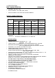
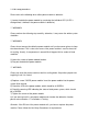
THE LED CONNECTOR OF TOTAL POWER SYSTEM
PIN# COLOR
1 RED
2 BLACK
3 GREEN
THE BUZZER RESET SWITCH CONNECTOR
PIN# COLOR
1 BLACK
2 YELLOW
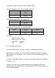
THE SIGNAL CONNECTOR OF POWER RESET
PIN# COLOR COLOR
1 RED TTL SIGNAL
2 BLACK GND
TTL signal:
Sink current max. 5mA
Source current max. 50uA
Low Active ---Defective
High ---Normal
1.10 TROUBLE SHOOTING
If you have followed these instructions correctly, it should function normally.
Some common symptoms are, the system doesn’t work, buzzer alarms, shutdown
after running a very short period,… etc. If so, please check the following steps to verify
and correct it.
1) Check all connection (if pinouts is correct, if any connection loosed, if the direction
is incorrect,… etc.).
2) Check if any short-circuit or defective peripherals by plugging out the power
connector from each peripheral, one at a time. Shall the system functions again, you
have solved the problem.