
Instruction Manual


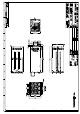
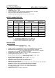
1.9 PINOUTS AND FUNCTION OF THE CONNECTORS
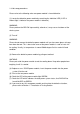
A. Power module defective signal:
PIN# VOLTAGE SPECIFICATION
1 GND
2 TTL SIGNAL pull up to +5Vsb
Low Active --- Defective
High --- Normal
B. Power status LED:
PIN# VOLTAGE SPECIFICATION
1 GND
2 12V Resistance 1K ohm to +12V
Low Active(blink) --- Defective
High (Green) --- Normal
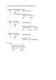
C. Buzzer reset switch:
PIN# VOLTAGE SPECIFICATION
2 GND
1 5V pull up to +5Vsb
Low Active --- on shoot trigger
TTL signal:
Sink current max. 5mA
Source current max. 50uA
Low Active ---Defective
High ---Normal