
Installation Guide


3
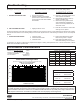
MODEL 375 1-1/4" - 2" (STANDARD & METRIC)
5
10
15
20
0 50 100 150 200 250
FLOW RATES (GPM)
PRESSURE LOSS
(PSIG)
34
69
103
138
0.0 3.2 6.3 9.5 12.6 15.8
FLOW RATES (l/s)
PRESSURE LOSS
(kpa)
If the reverse side of the seal ring is unused, it is possible
to invert the seal ring. This would be considered a tem-
porary solution to xing a fouled check and should be re-
placed with a new seal ring as soon as possible.
7. Inspect seat surface for nicks or dings and replace if
necessary. Use ngernail to check for dings.
Re-grease seat o-rings.
8. Inspect seat o-ring sealing areas in body and wipe clean.
9. Reverse the above procedures to reinstall check valve
assembly. Drop #2 check assembly in body. Then drop
#1 check assembly in and turn until #1 spring retainer
lines up with #2 seat. Then push both assemblies into
body. Insert sleeve against checks. (Place sleeve down
against at surface and push on body with rocking motion.)
Care should be taken to make sure the heavy spring is
installed in the No. 1 check valve.
10. Rock body side to side to help o-rings slide in. If it does
not drop in completely, do not use screws to force it.
An overly greased o-ring might slide out of groove at top
of ball valve. Use a screw driver to push o-ring back in
groove, then push body down in.
SERVICING RELIEF VALVE
1. Remove three bolts holding relief valve module to body.
2. Pull down and remove relief module to expose seat and
seal ring. These can be inspected without further disas-
sembly. CAUTION: do not lose small o-ring or large o-ring
that t between module and check body.
3. To inspect diaphragm or replace seat/diaphragm stem
assembly, remove the four screws holding the two module
halves together. CAUTION: do not lose small o-ring.
4. Remove stem assembly. Inspect diaphragm and plunger
o-ring for damage. Replace any damaged parts and ap-
ply a light coat of grease to plunger o-ring and place on
plunger. CAUTION: stem assembly is internally spring
loaded. Seat can be unscrewed from plunger to replace
diaphragm or spring. The seat surface must not be nicked
during disassembly or reassembly.
5. There are two o-rings that t into the cover surface, one
large, one small. These o-rings should not be greased.
Insert stem into cover. Place second module half onto
cover. Push the seat down into the cover with your thumb
to align diaphragm bolt holes with cover and then insert
four bolts and tighten.
6. Inspect o-ring that seals between module and check body.
Replace if necessary. Apply grease to the o-ring and then
place on step on check body. Place small o-ring into groove
between the two front bolts holes in relief valve module.
7. Slide relief valve module onto check body. Rocking side
to side can help it slide on over o-ring. Replace three
remaining bolts.
8. Place device in service and test per "TESTING PROCE-
DURES.
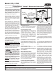
Maintenance Instructions
BODY
BODY OUTLET
O-RING
RV
COVER O-RING
RV SENSING
PORT O-RING
RV SPRING
RV BODY
FLANGE
RV SEAL
RING RETAINER
RV COVER
BOLTS
RV DIAPHRAGM
RV SENSING
PORT O-RING
RV PLUNGER
O-RING
RV COVER
RV COVER BOLTS
& NUTS
RV SPRING GUIDE
RV SEAT
RV SEAL RING
RV BODY
O-RING
RV SCREW
BOLT
RV
PLUNGER
SLEEVE
O-RING
SLEEVE
BOLT
BODY INLET
O-RING
2" (50mm)
1-1/4" (32mm)
1-1/2" (40mm)
⃟
Rated Flow (Established by approval agencies)
FLOW CHARACTERISTICS
SEAT O-RING
#1 CHECK SEAT
POPPET SCREW
SEAL RING RETAINER
POPPET SEAL RING
POPPET
#1 CHECK SPRING
#1 CHECK SPRING
RETAINER
#2 CHECK ASSY
SPACER (1-1/4” & 1-1/2”)
ZURN WILKINS
1747 Commerce Way, Paso Robles, CA 93446 Phone:855-663-9876 Fax:805-238-5766
®
www.zurn.com