
Specification

ഌ
. / 0 1 2 3 4 5 6 7 1 8 0 / 9 4 : 8 ; 1 2 9 < / = = > 5 ? / 4 / @ 1 A B : 1 8 C
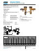
Flow Characteristics
Zurn Industries, LLC
| Wilkins
1747 Commerce Way, Paso Robles, CA U.S.A. 93446 Ph. 855-663-9876, Fax 805-238-5766
In Canada | Zurn Industries Limited
3544 Nashua Drive, Mississauga, Ontario L4V 1L2 Ph. 905-405-8272, Fax 905-405-1292
www.zurn.com
Page 2 of 2
0 10 20 30 40 50
0
5
10
0 40 80 120 160 200
0
5
10
60
FLOW RATES (GPM)
PRESSURE LOSS (PSIG)
69
PRESSURE LOSS (kpa)
FLOW RATES (l/s)
MODEL 720A 1/2", 3/4", 1", 1 1/4", 1 1/2" & 2" (STANDARD & METRIC)
35
1/2" (15mm)
3/4" (20mm)
1" (25mm)
1 1/4" (32mm)
1 1/2" (40mm)
2" (50mm)
12.6
10.1
7.6
5.0
2.52
3.8
3.22.52
1.89
1.26
0.63
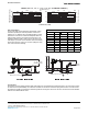
Typical Installation
Local codes shall govern installation requirements. Unless
otherwise specified, the assembly shall be mounted at a
minimum of 12" (305mm) above the highest piping or outlet
downstream of the device. Install with adequate drain and
sufficient side clearance for testing and maintenance. The
installation shall be made so that no part of the unit can be
submerged. A pressure vacuum breaker cannot be installed
where back-pressure could occur or where spillage of water
from vent could cause damage.
Speci cations
The Pressure Vacuum Breaker shall be ASSE 1020 approved, and supplied with full port ball valves. The main body and bon-
net shall be bronze (ASTM B584), the loaded-air inlet shall use an silicone elastomer spring and seat disc. The entire assem-
bly shall be accessible for maintenance and testing without removing the device from the line. The Pressure Vacuum Breaker
shall be a Zurn Wilkins Model 720A.
D E F G G H D E I J K L L K J D G EG M J F G G H D E I J K L L K J D G E
N O P O Q R S T S U V W X Q U Y Z W [ Y \ ] ^ R P Y
^ R P Y _ R ` Y a b S c _ Y Q d e a b S c _ Y Q f ] b S c _ Y Q f a b S c _ Y Q
f c g h f f i j
f c \ h i i j a
j c g h j \ k l
f c i a d l f \
j c \ h g f i f d i a
f h f j i ] i d \ ]
f f c \ h i j j a \ d d ]
f f c i h j i \ g k j l a
i h a i d g f ] a f k d
12" MIN. ABOVE
HIGHEST OUTLET
DIRECTION OF FLOW
12" MIN. ABOVE
HIGHEST PIPING
DIRECTION OF FLOW