
Installation Guide

INSTALLATION INSTRUCTIONS
CAUTION: Installation of Backow Preventers must be performed by qualied, licensed
personnel. The installer should be sure the proper device has been selected for the par-
ticular installation. Faulty installation could result in an improperly functioning device.
ZURN WILKINS Model 350 Double Check Valve assemblies are for use on water lines
where a health hazard does not exist in the event of a backow situation.
Damage to the device could result wherever water hammer and/or water thermal expan-
sion could create excessive line pressure. Where this could occur, shock arresters, check
valves and/or pressure relief valves should be installed downstream of the device.
If installation is in a pit or vault, the Backow Preventer must never be submerged in
water because this could cause a cross-connection. Make sure that the pit or vault always
remains dry by providing ample drainage.
1. Before installing a Model 350 Backow Preventer, ush the line thoroughly to
remove all debris, chips and other foreign matter. If required, a strainer should be
placed upstream of the Backow Preventer. CAUTION: Do not use a strainer in
seldom used emergency waterlines such as re lines.
2. Provide adequate space around the installed unit so that the test cocks will be
accessible for testing and servicing.
3. Install valve at least 12 inches above surrounding ood level.
4. Always consult local codes for installation methods, approvals and guidance.
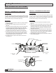
INDOOR INSTALLATION
Indoor installation is preferred in areas
that are subject to freezing conditions. All
the basic installation instructions apply to
such installations.
OUTDOOR INSTALLATION
The Model 350 Backow Preventer may
be installed outdoors only if the device
is protected against freezing conditions.
Exposure to freezing conditions will result
in improper function or damage to the
device. The installation location must be
kept above 32°F. All the basic installation
instructions apply.
PLACING THE MODEL 350 IN SERVICE
1. Start with both shut-off valves closed.
Slowly open the inlet shut-off valve until the
backow preventer is completely pressur-
ized.
2. When the unit has been pressurized,
vent any trapped air by slightly opening
each of the four test cocks.
3. Slowly open the downstream shut-off
valve. The Model 350 Double Check Valve
assembly is now in service.
4. After the Model 350 has been prop-
erly installed, test the device (see “TEST
PROCEDURES”). If the device fails the
test, remove the rst and second check
valves and thoroughly ush the device.
Clean rubber and seats of all debris and
place unit back in service.
VERTICAL INSTALLATION
Vertical installation is acceptable in applica-
tions where inlet and outlet piping are ow-
ing vertically upwards. All the basic installa-
tion instructions apply to such installations.
Consult factory for approval status.
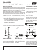
Installation Testing Maintenance Instructions
Model 350
Double Check Valve Assembly (1-1/4”- 2”)
2
DIRECTION OF FLOW
2
12" MIN.
30" MAX.
DIRECTION OF FLOW
2
OPTIONAL STRAINER
(MODEL SXL)
PROTECTIVE
ENCLOSURE
2
DIRECTION OF FLOW
Proposition 65 Warning This product contains chemicals known to the State of California to cause cancer
or birth defects or other reproductive harm.
®
In accordance with U.S. Federal Safe Drinking Water Act Lead-Free requirements, as of January 4, 2014, this product can only be used in water
systems considered non-potable. Please contact your local water utility for further requirements.