
Installation Guide

Maintenance Instructions
ZURN WILKINS
1747 Commerce Way, Paso Robles, CA 93446 Phone:855-663-9876 Fax:805-238-5766
3
When the relief valve discharges intermittently it can be almost always assumed that the device is functioning correctly and that the
discharge is caused by systems such as inlet pressure uctuations or water hammer due to quick closing valves.
Continuous discharge of the relief valve signies a failure of some part of the device. To help determine the specic area of failure, close
the #2 shut-off valve. If the discharge stops, the #2 check requires service. If the discharge continues, the #1 check requires service.
In summation, the amount of discharge is proportional to degree of fouling. Most problems occur in the #1 check which is where
debris enters the backow preventer rst.
All Model 975XL2 Reduced Pressure Principle Backow Preven-
ters must be inspected and maintained by licensed personnel at
least once a year or more frequently as specied by local codes.
Replacement of worn or damaged parts must only be made with
genuine "ZURN WILKINS" parts. The ZURN WILKINS Certicate
of Limited Warranty provides that failure to do so "...releases
ZURN WILKINS of any liability that it might otherwise have with
respect to that device." Such failure could also result in an im-
properly functioning device.
The Model 975XL2 Reduced Pressure Principle Assemblies
should be thoroughly ushed after backow conditions occur to
prevent any type of corrosive deterioration to its components.
Failure to do so could result in malfunction of the device.
GENERAL MAINTENANCE
1. Clean all parts thoroughly with water after disassembly.
2. Carefully inspect rubber seal rings, diaphragms and o-rings
for damage.
3. Test unit after reassembly for proper operation (see "Testing
Procedures").
SERVICING CHECK VALVES
1. Close inlet and outlet shut-off valves.
2. Open No. 2, No. 3 and No. 4 test cocks to release pressure
from valve.
3.Unscrew check valve covers using appropriate size wrench
(CAUTION: Cover is spring loaded). To avoid injury, hold cover
down rmly with one hand while unscrewing.
4. Remove check valve cover, spring and poppet assembly.
5. Inspect the rubber seal ring for cuts or embedded debris. To
remove seal ring, remove screw and seal ring retainer. If the
reverse side of the seal ring is unused, it is possible to invert the
seal ring. This would be considered a temporary solution to xing
a fouled check and should be replaced with a new seal ring as
soon as possible.
6. Inspect valve cavity and seating area. Remove any debris.
7. If installed with removable seat, unscrew seat from body and
replace with new seat and lightly grease o-ring.*
8. Reverse the above procedures to reinstall check valve as-
sembly. Care should be taken to make sure the heavy spring
is installed in the No. 1 check valve. For the 3/4"-1" 975XL2SE
the No. 2 poppet has a cupped seal retainer. For the 1 1/4"-2"
975XL2SE the No. 1 seat has a taller seat prole than the
No. 2 seat.
SERVICING RELIEF VALVE
1. Remove relief valve cover bolts and cover. Gently pull on dia-
phragm to remove the cartridge assembly.
2. Inspect seal ring for cuts and embedded debris. Turn over or
replace if required.
3. Disassemble cartridge by unscrewing relief valve retaining screw.
4. Inspect diaphragm and o-rings for damage. Replace required
parts and apply a light coat of grease to plunger o-ring.
5. Carefully reassemble cartridge assembly.
6. Inspect relief valve seat for wear on seating surface. If dam-
aged, replace seat and seat o-ring.*
7. Insert cartridge assembly into relief valve body.
8. Replace relief valve cover and cover bolts.
9. Place device in service and test per "TESTING PROCEDURES".
*For seat removal assistance, consult factory.
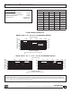
Troubleshooting
PROBLEM
1. SUDDEN OR RAPID SPITTING
2. LIGHT INTERMITTENT DRIP
POSSIBLE CAUSES
1. Drop in inlet pressure.
2. Sudden increase in downstream pressure
due to water hammer from quick closing
shut-off valve installed downstream.
1. Slightly fouled #1 check.
CORRECTIVE ACTION
A. Install an in-line spring loaded check
valve upstream of backow.
B. Install pressure reducing valve upstream
of backow unit.
C. Install in-line spring loaded check valve
downstream of backow as close to source
as possible, but not closer that 4 feet.
A. Clean #1 check and turn check valve
seal ring over or replace.
1. CONTINUOUS DISCHARGE
1. Fouled #1 check.
2. Fouled relief valve seat.
3. Fouled #2 check
A. Clean check valves and turn check valve
seal rings over or replace.
B. Clean relief valve seat and turn relief
valve seal ring over or replace.
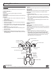
O-RING(PLUNGER)
RELIEF VALVE COVER
COVER BOLTS
PLUNGER(UPPER)
DIAPHRAGM
PLUNGER
(LOWER)
SEAL RING
(RELIEF VALVE)
SEAL RING RETAINER
(RELIEF VALVE)
SPRING
(RELIEF VALVE)
RETAINING SCREW
(RELIEF VALVE)
SEAT O-RING
(RELIEF VALVE)
SEAT(RELIEF VALVE)
SPRING(CHECK)
O-RING
(COVER)
COVER(CHECK)
POPPET
SEAL RING
(CHECK)
SEAL RING RETAINER
(CHECK)
RETAINING SCREW
(CHECK)
SEAT(CHECK)
O-RING
(CHECK SEAT)
www.zurn.com
®