Prestige 660R-6xC Series ADSL/ADSL2/ADSL2+ Router User’s Guide Version 3.
Prestige 660R-6xC Series User’s Guide Copyright Copyright © 2004 by ZyXEL Communications Corporation. The contents of this publication may not be reproduced in any part or as a whole, transcribed, stored in a retrieval system, translated into any language, or transmitted in any form or by any means, electronic, mechanical, magnetic, optical, chemical, photocopying, manual, or otherwise, without the prior written permission of ZyXEL Communications Corporation. Published by ZyXEL Communications Corporation.
Prestige 660R-6xC Series User’s Guide Federal Communications Commission (FCC) Interference Statement This device complies with Part 15 of FCC rules. Operation is subject to the following two conditions: • This device may not cause harmful interference. • This device must accept any interference received, including interference that may cause undesired operations. This equipment has been tested and found to comply with the limits for a Class B digital device pursuant to Part 15 of the FCC Rules.
Prestige 660R-6xC Series User’s Guide ZyXEL Limited Warranty ZyXEL warrants to the original end user (purchaser) that this product is free from any defects in materials or workmanship for a period of up to two years from the date of purchase.
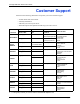
Prestige 660R-6xC Series User’s Guide Customer Support Please have the following information ready when you contact customer support. • • • • Product model and serial number. Warranty Information. Date that you received your device. Brief description of the problem and the steps you took to solve it. METHOD SUPPORT E-MAIL TELEPHONEA WEB SITE LOCATION SALES E-MAIL FAX FTP SITE support@zyxel.com.tw +886-3-578-3942 WORLDWIDE NORTH AMERICA GERMANY DENMARK NORWAY SWEDEN FINLAND www.zyxel.
Prestige 660R-6xC Series User’s Guide Table of Contents Copyright .................................................................................................................. 2 Federal Communications Commission (FCC) Interference Statement ............... 3 ZyXEL Limited Warranty.......................................................................................... 4 Customer Support....................................................................................................
Prestige 660R-6xC Series User’s Guide 3.1.1.1 ENET ENCAP .................................................................................40 3.1.1.2 PPP over Ethernet ..........................................................................40 3.1.1.3 PPPoA .............................................................................................40 3.1.1.4 RFC 1483 ........................................................................................41 3.1.2 Multiplexing ...............................
Prestige 660R-6xC Series User’s Guide Chapter 6 WAN Setup.............................................................................................................. 60 6.1 WAN Overview ...................................................................................................60 6.2 Metric ................................................................................................................60 6.3 PPPoE Encapsulation .......................................................................
Prestige 660R-6xC Series User’s Guide 10.1.3 System Timeout .....................................................................................87 10.2 Telnet ................................................................................................................87 10.3 FTP ..................................................................................................................87 10.4 Web ......................................................................................................
Prestige 660R-6xC Series User’s Guide Chapter 15 Menu 2 WAN Backup Setup ................................................................................ 124 15.1 Introduction to WAN Backup Setup ................................................................124 15.2 Configuring Dial Backup in Menu 2 ................................................................124 15.2.1 Traffic Redirect Setup ...........................................................................126 Chapter 16 Menu 3 LAN Setup ..
Prestige 660R-6xC Series User’s Guide Chapter 19 Static Route Setup ............................................................................................... 150 19.1 IP Static Route Overview ...............................................................................150 19.2 Configuration ..................................................................................................150 Chapter 20 Bridging Setup ..................................................................................
Prestige 660R-6xC Series User’s Guide Chapter 23 SNMP Configuration ............................................................................................ 188 23.1 About SNMP ..................................................................................................188 23.2 Supported MIBs ............................................................................................189 23.3 SNMP Configuration ......................................................................................
Prestige 660R-6xC Series User’s Guide Chapter 26 System Maintenance............................................................................................ 214 26.1 Command Interpreter Mode ...........................................................................214 26.2 Call Control Support .......................................................................................215 26.2.1 Budget Management ............................................................................215 26.
Prestige 660R-6xC Series User’s Guide Appendix A Splitters and Microfilters ..................................................................................... 242 Connecting a POTS Splitter ................................................................................... 242 Telephone Microfilters ............................................................................................ 242 Prestige With ISDN ...........................................................................................
Prestige 660R-6xC Series User’s Guide Appendix F Command Interpreter........................................................................................... 268 Command Syntax................................................................................................... 268 Command Usage ................................................................................................... 268 Appendix G Log Descriptions...................................................................................
Prestige 660R-6xC Series User’s Guide List of Figures Figure 1 Prestige Internet Access Application .................................................................... 34 Figure 2 Prestige LAN-to-LAN Application .......................................................................... 35 Figure 3 Password Screen .................................................................................................. 36 Figure 4 Change Password at Login ..........................................................
Prestige 660R-6xC Series User’s Guide Figure 37 Windows Optional Networking Components Wizard .......................................... 94 Figure 38 Networking Services ........................................................................................... 95 Figure 39 Network Connections .......................................................................................... 96 Figure 40 Internet Connection Properties ..........................................................................
Prestige 660R-6xC Series User’s Guide Figure 80 Menu 21.12 WebSet 12 ...................................................................................... 147 Figure 81 Menu 11.6 for VC-based Multiplexing ................................................................. 148 Figure 82 Menu 11.6 for LLC-based Multiplexing or PPP Encapsulation ............................ 148 Figure 83 Menu 11.1 Remote Node Profile .........................................................................
Prestige 660R-6xC Series User’s Guide Figure 123 Sample Telnet Filter .......................................................................................... 184 Figure 124 Menu 21.6.1 Sample Filter ............................................................................... 185 Figure 125 Menu 21.6.1 Sample Filter Rules Summary ..................................................... 185 Figure 126 Filtering Ethernet Traffic ...............................................................................
Prestige 660R-6xC Series User’s Guide Figure 166 Connecting a POTS Splitter .............................................................................. 242 Figure 167 Connecting a Microfilter .................................................................................... 243 Figure 168 Prestige with ISDN ............................................................................................ 243 Figure 169 WIndows 95/98/Me: Network: Configuration .................................................
Prestige 660R-6xC Series User’s Guide 21
Prestige 660R-6xC Series User’s Guide List of Tables Table 1 ADSL Standards .................................................................................................... 30 Table 2 Web Configurator Screens Summary .................................................................... 38 Table 3 Internet Access Wizard Setup: First Screen .......................................................... 42 Table 4 Internet Connection with PPPoE .................................................................
Prestige 660R-6xC Series User’s Guide Table 37 DHCP Ethernet Setup ......................................................................................... 130 Table 38 TCP/IP Ethernet Setup ........................................................................................ 130 Table 39 Menu 3.2.1 IP Alias Setup ................................................................................... 134 Table 40 Menu 4 Internet Access Setup ..................................................................
Prestige 660R-6xC Series User’s Guide Table 80 Troubleshooting Remote Management ............................................................... 241 Table 81 Classes of IP Addresses ..................................................................................... 256 Table 82 Allowed IP Address Range By Class ................................................................... 257 Table 83 “Natural” Masks ..................................................................................................
Prestige 660R-6xC Series User’s Guide 25
Prestige 660R-6xC Series User’s Guide Preface Congratulations on your purchase of the Prestige 660R-6xC ADSL/ADSL2/ADSL2+ Router. Note: Register your product online to receive e-mail notices of firmware upgrades and information at www.zyxel.com for global products, or at www.us.zyxel.com for North American products. Your Prestige is easy to install and configure. About This User's Guide This manual is designed to guide you through the configuration of your Prestige for its various applications.
Prestige 660R-6xC Series User’s Guide The Quick Start Guide is designed to help you get up and running right away. They contain connection information and instructions on getting started. • Web Configurator Online Help Embedded web help for descriptions of individual screens and supplementary information. • ZyXEL Glossary and Web Site Please refer to www.zyxel.com for an online glossary of networking terms and additional support documentation. User Guide Feedback Help us help you.
Prestige 660R-6xC Series User’s Guide Introduction to DSL DSL (Digital Subscriber Line) technology enhances the data capacity of the existing twistedpair wire that runs between the local telephone company switching offices and most homes and offices.
Prestige 660R-6xC Series User’s Guide 29 Introduction to DSL
Prestige 660R-6xC Series User’s Guide CHAPTER 1 Getting To Know Your Prestige This chapter describes the key features and applications of your Prestige. 1.1 Introducing the Prestige Your Prestige integrates high-speed 10/100Mbps auto-negotiating LAN interface(s) and a high-speed ADSL port into a single package. The Prestige is ideal for high-speed Internet browsing and making LAN-to-LAN connections to remote networks. The Prestige is an ADSL router compatible with the ADSL/ADSL2/ADSL2+ standards.
Prestige 660R-6xC Series User’s Guide High Speed Internet Access Your Prestige ADSL/ADSL2/ADSL2+ router can support downstream transmission rates of up to 24Mbps and upstream transmission rates of 3.5Mbps. Actual speeds attained depend on ISP DSLAM environment. Traffic Redirect Traffic redirect forwards WAN traffic to a backup gateway when the Prestige cannot connect to the Internet, thus acting as an auxiliary if your regular WAN connection fails.
Prestige 660R-6xC Series User’s Guide Multiple PVC (Permanent Virtual Circuits) Support Your Prestige supports up to 8 PVC’s. ADSL Standards • Full-Rate (ANSI T1.413, Issue 2; G.dmt (G.992.1) with line rate support of up to 8 Mbps downstream and 832 Kbps upstream. • G.lite (G.992.2) with line rate support of up to 1.5Mbps downstream and 512Kbps upstream. • Supports Multi-Mode standard (ANSI T1.413, Issue 2; G.dmt (G.992.1); G.lite (G992.2)).
Prestige 660R-6xC Series User’s Guide • ICMP support • ATM QoS support • MIB II support (RFC 1213) Networking Compatibility Your Prestige is compatible with the major ADSL DSLAM (Digital Subscriber Line Access Multiplexer) providers, making configuration as simple as possible for you. Multiplexing The Prestige supports VC-based and LLC-based multiplexing.
Prestige 660R-6xC Series User’s Guide • LAN port Packet Filters The Prestige's packet filtering functions allows added network security and management. Ease of Installation Your Prestige is designed for quick, intuitive and easy installation. Housing Your Prestige's compact and ventilated housing minimizes space requirements making it easy to position anywhere in your busy office. 1.1.2 Applications for the Prestige Here are some example uses for which the Prestige is well suited. 1.1.2.
Prestige 660R-6xC Series User’s Guide Figure 2 Prestige LAN-to-LAN Application 1.1.3 Prestige Hardware Installation and Connection Refer to the Quick Start Guide for information on hardware installation and connection and LED descriptions.
Prestige 660R-6xC Series User’s Guide CHAPTER 2 Introducing the Web Configurator This chapter describes how to access and navigate the web configurator. 2.1 Web Configurator Overview The web configurator is an HTML-based management interface that allows easy Prestige setup and management via Internet browser. Use Internet Explorer 6.0 and later or Netscape Navigator 7.0 and later versions with JavaScript enabled. Recommended screen resolution is 1024 by 768 pixels. 2.1.
Prestige 660R-6xC Series User’s Guide 6 It is highly recommended you change the default password! Enter a new password, retype it to confirm and click Apply; alternatively click Ignore to proceed to the main menu if you do not want to change the password now. Note: If you do not change the password, the following screen appears every time you log in. Figure 4 Change Password at Login 7 You should now see the SITE MAP screen. Note: The Prestige automatically times out after five minutes of inactivity.
Prestige 660R-6xC Series User’s Guide • Click Wizard Setup to begin a series of screens to configure your Prestige for the first time. • Click a link under Advanced Setup to configure advanced Prestige features. • Click a link under Maintenance to see Prestige performance statistics, upload firmware and back up, restore or upload a configuration file. • Click Site Map to go to the Site Map screen. • Click Logout in the navigation panel when you have finished a Prestige management session.
Prestige 660R-6xC Series User’s Guide Table 2 Web Configurator Screens Summary (continued) LINK SUB-LINK FUNCTION Remote Management Use this screen to configure through which interface(s) and from which IP address(es) users can use Telnet/FTP/Web to manage the Prestige. UPnP Use this screen to enable UPnP on the Prestige. Maintenance System Status This screen contains administrative and system-related information.
Prestige 660R-6xC Series User’s Guide CHAPTER 3 Wizard Setup This chapter provides information on the Wizard Setup screens for Internet access in the web configurator. 3.1 Introduction Use the Wizard Setup screens to configure your system for Internet access with the information (provided by your ISP) that you fill in the Internet Account Information table in the Quick Start Guide. Your ISP may have already configured some of the fields in the wizard screens for you. 3.1.
Prestige 660R-6xC Series User’s Guide 3.1.1.4 RFC 1483 RFC 1483 describes two methods for Multiprotocol Encapsulation over ATM Adaptation Layer 5 (AAL5). The first method allows multiplexing of multiple protocols over a single ATM virtual circuit (LLC-based multiplexing) and the second method assumes that each protocol is carried over a separate ATM virtual circuit (VC-based multiplexing). Please refer to the RFC for more detailed information. 3.1.
Prestige 660R-6xC Series User’s Guide Figure 6 Internet Access Wizard Setup: First Screen The following table describes the labels in this screen. Table 3 Internet Access Wizard Setup: First Screen LABEL DESCRIPTION Mode From the Mode drop-down list box, select Routing (default) if your ISP allows multiple computers to share an Internet account. Otherwise select Bridge. Encapsulation Select the encapsulation type your ISP uses from the Encapsulation drop-down list box.
Prestige 660R-6xC Series User’s Guide If the ISP did not explicitly give you an IP network number, then most likely you have a single user account and the ISP will assign you a dynamic IP address when the connection is established. If this is the case, it is recommended that you select a network number from 192.168.0.0 to 192.168.255.0 and you must enable the Network Address Translation (NAT) feature of the Prestige.
Prestige 660R-6xC Series User’s Guide 3.2.1.4 Private IP Addresses Every machine on the Internet must have a unique address. If your networks are isolated from the Internet, for example, only between your two branch offices, you can assign any IP addresses to the hosts without problems. However, the Internet Assigned Numbers Authority (IANA) has reserved the following three blocks of IP addresses specifically for private networks: • 10.0.0.0 — 10.255.255.255 • 172.16.0.0 — 172.31.255.255 • 192.168.0.
Prestige 660R-6xC Series User’s Guide Figure 7 Internet Connection with PPPoE The following table describes the labels in this screen. Table 4 45 Internet Connection with PPPoE LABEL DESCRIPTION Service Name Type the name of your PPPoE service here. User Name Enter the user name exactly as your ISP assigned. If assigned a name in the form user@domain where domain identifies a service name, then enter both components exactly as given.
Prestige 660R-6xC Series User’s Guide Figure 8 Internet Connection with RFC 1483 The following table describes the labels in this screen. Table 5 Internet Connection with RFC 1483 LABEL DESCRIPTION IP Address This field is available if you select Routing in the Mode field. Type your ISP assigned IP address in this field. Network Address Translation Select None, SUA Only or Full Feature from the drop-down list box. Refer to Chapter 7, on page 70 for more details.
Prestige 660R-6xC Series User’s Guide The following table describes the labels in this screen. Table 6 Internet Connection with ENET ENCAP LABEL DESCRIPTION IP Address A static IP address is a fixed IP that your ISP gives you. A dynamic IP address is not fixed; the ISP assigns you a different one each time you connect to the Internet. .
Prestige 660R-6xC Series User’s Guide The following table describes the labels in this screen. Table 7 Internet Connection with PPPoA LABEL DESCRIPTION User Name Enter the login name that your ISP gives you. Password Enter the password associated with the user name above. IP Address This option is available if you select Routing in the Mode field. A static IP address is a fixed IP that your ISP gives you.
Prestige 660R-6xC Series User’s Guide Figure 11 Internet Access Wizard Setup: Third Screen If you want to change your Prestige LAN settings, click Change LAN Configuration to display the screen as shown next.
Prestige 660R-6xC Series User’s Guide Figure 12 Internet Access Wizard Setup: LAN Configuration The following table describes the labels in this screen. Table 8 Internet Access Wizard Setup: LAN Configuration LABEL DESCRIPTION LAN IP Address Enter the IP address of your Prestige in dotted decimal notation, for example, 192.168.1.1 (factory default). Note: If you changed the Prestige's LAN IP address, you must use the new IP address if you want to access the web configurator again.
Prestige 660R-6xC Series User’s Guide 3.2.7 Internet Access Wizard Setup: Connection Test The Prestige automatically tests the connection to the computer(s) connected to the LAN ports. To test the connection from the Prestige to the ISP, click Start Diagnose. Otherwise click Return to Main Menu to go back to the Site Map screen. Figure 13 Internet Access Wizard Setup: Connection Tests 3.2.7.1 Test Your Internet Connection Launch your web browser and navigate to www.zyxel.com.
Prestige 660R-6xC Series User’s Guide CHAPTER 4 Password Setup This chapter provides information on the Password screen. 4.1 Password Overview It is highly recommended that you change the password for accessing the Prestige. 4.1.1 Configuring Password To change your Prestige’s password (recommended), click Password in the Site Map screen. The screen appears as shown. Figure 14 Password The following table describes the fields in this screen.
Prestige 660R-6xC Series User’s Guide 53 Chapter 4 Password Setup
Prestige 660R-6xC Series User’s Guide CHAPTER 5 LAN Setup This chapter describes how to configure LAN settings. 5.1 LAN Overview A Local Area Network (LAN) is a shared communication system to which many computers are attached. A LAN is a computer network limited to the immediate area, usually the same building or floor of a building. The LAN screens can help you configure a LAN DHCP server and manage IP addresses. 5.1.
Prestige 660R-6xC Series User’s Guide 5.2 DNS Server Address DNS (Domain Name System) is for mapping a domain name to its corresponding IP address and vice versa. The DNS server is extremely important because without it, you must know the IP address of a machine before you can access it. The DNS server addresses that you enter in the DHCP setup are passed to the client machines along with the assigned IP address and subnet mask. There are two ways that an ISP disseminates the DNS server addresses.
Prestige 660R-6xC Series User’s Guide 5.4 LAN TCP/IP The Prestige has built-in DHCP server capability that assigns IP addresses and DNS servers to systems that support DHCP client capability. 5.4.1 Factory LAN Defaults The LAN parameters of the Prestige are preset in the factory with the following values: • IP address of 192.168.1.1 with subnet mask of 255.255.255.0 (24 bits) • DHCP server enabled with 32 client IP addresses starting from 192.168.1.33.
Prestige 660R-6xC Series User’s Guide 5.4.4 Multicast Traditionally, IP packets are transmitted in one of either two ways - Unicast (1 sender - 1 recipient) or Broadcast (1 sender - everybody on the network). Multicast delivers IP packets to a group of hosts on the network - not everybody and not just 1. IGMP (Internet Group Multicast Protocol) is a network-layer protocol used to establish membership in a Multicast group - it is not used to carry user data.
Prestige 660R-6xC Series User’s Guide Figure 16 LAN Setup The following table describes the labels in this screen. Table 10 LAN Setup LABEL DESCRIPTION DHCP DHCP If set to Server, your Prestige can assign IP addresses, an IP default gateway and DNS servers to Windows 95, Windows NT and other systems that support the DHCP client. If set to None, the DHCP server will be disabled.
Prestige 660R-6xC Series User’s Guide Table 10 LAN Setup (continued) 59 LABEL DESCRIPTION IP Address Enter the IP address of your Prestige in dotted decimal notation, for example, 192.168.1.1 (factory default). IP Subnet Mask Type the subnet mask assigned to you by your ISP (if given). RIP Direction Select the RIP direction from None, Both, In Only and Out Only. RIP Version Select the RIP version from RIP-1, RIP-2B and RIP-2M.
Prestige 660R-6xC Series User’s Guide CHAPTER 6 WAN Setup This chapter describes how to configure WAN settings. 6.1 WAN Overview A WAN (Wide Area Network) is an outside connection to another network or the Internet. See Chapter 3 Wizard Setupfor more information on the fields in the WAN screens. 6.2 Metric The metric represents the "cost of transmission". A router determines the best route for transmission by choosing a path with the lowest "cost".
Prestige 660R-6xC Series User’s Guide 6.3 PPPoE Encapsulation The Prestige supports PPPoE (Point-to-Point Protocol over Ethernet). PPPoE is an IETF Draft standard (RFC 2516) specifying how a personal computer (PC) interacts with a broadband modem (DSL, cable, wireless, etc.) connection. The PPPoE option is for a dial-up connection using PPPoE. For the service provider, PPPoE offers an access and authentication method that works with existing access control systems (for example Radius).
Prestige 660R-6xC Series User’s Guide Figure 17 Example of Traffic Shaping 6.5 Configuring WAN Setup To change your Prestige’s WAN remote node settings, click WAN and WAN Setup. The screen differs by the encapsulation.
Prestige 660R-6xC Series User’s Guide Figure 18 WAN Setup (PPPoE) The following table describes the labels in this screen. Table 11 WAN Setup 63 LABEL DESCRIPTION Name Enter the name of your Internet Service Provider, e.g., MyISP. This information is for identification purposes only. Mode Select Routing (default) from the drop-down list box if your ISP allows multiple computers to share an Internet account. Otherwise select Bridge.
Prestige 660R-6xC Series User’s Guide Table 11 WAN Setup (continued) LABEL DESCRIPTION Encapsulation Select the method of encapsulation used by your ISP from the drop-down list box. Choices vary depending on the mode you select in the Mode field. If you select Bridge in the Mode field, select either PPPoA or RFC 1483. If you select Routing in the Mode field, select PPPoA, RFC 1483, ENET ENCAP or PPPoE. Multiplex Select the method of multiplexing used by your ISP from the drop-down list.
Prestige 660R-6xC Series User’s Guide Table 11 WAN Setup (continued) LABEL DESCRIPTION Max Idle Timeout Specify an idle time-out in the Max Idle Timeout field when you select Connect on Demand. The default setting is 0, which means the Internet session will not timeout. PPPoE Passthrough This field is available when you select PPPoE encapsulation.
Prestige 660R-6xC Series User’s Guide Figure 19 Traffic Redirect Example The following network topology allows you to avoid triangle route security issues when the backup gateway is connected to the LAN. Use IP alias to configure the LAN into two or three logical networks with the Prestige itself as the gateway for each LAN network. Put the protected LAN in one subnet (Subnet 1 in the following figure) and the backup gateway in another subnet (Subnet 2).
Prestige 660R-6xC Series User’s Guide Figure 21 WAN Backup The following table describes the labels in this screen. Table 12 WAN Backup LABEL DESCRIPTION Backup Type Select the method that the Prestige uses to check the DSL connection. Select DSL Link to have the Prestige check if the connection to the DSLAM is up. Select ICMP to have the Prestige periodically ping the IP addresses configured in the Check WAN IP Address fields.
Prestige 660R-6xC Series User’s Guide Table 12 WAN Backup (continued) LABEL DESCRIPTION Traffic Redirect Active Select this check box to have the Prestige use traffic redirect if the normal WAN connection goes down. Note: If you activate traffic redirect, you must configure at least one Check WAN IP Address. Metric This field sets this route's priority among the routes the Prestige uses. The metric represents the "cost of transmission".
Prestige 660R-6xC Series User’s Guide 69 Chapter 6 WAN Setup
Prestige 660R-6xC Series User’s Guide CHAPTER 7 Network Address Translation (NAT) Screens This chapter discusses how to configure NAT on the Prestige. 7.1 NAT Overview NAT (Network Address Translation - NAT, RFC 1631) is the translation of the IP address of a host in a packet, for example, the source address of an outgoing packet, used within one network to a different IP address known within another network. 7.1.
Prestige 660R-6xC Series User’s Guide Note: NAT never changes the IP address (either local or global) of an outside host. 7.1.2 What NAT Does In the simplest form, NAT changes the source IP address in a packet received from a subscriber (the inside local address) to another (the inside global address) before forwarding the packet to the WAN side.
Prestige 660R-6xC Series User’s Guide Figure 22 How NAT Works 7.1.4 NAT Application The following figure illustrates a possible NAT application, where three inside LANs (logical LANs using IP Alias) behind the Prestige can communicate with three distinct WAN networks. More examples follow at the end of this chapter. Figure 23 NAT Application With IP Alias 7.1.5 NAT Mapping Types NAT supports five types of IP/port mapping.
Prestige 660R-6xC Series User’s Guide • One to One: In One-to-One mode, the Prestige maps one local IP address to one global IP address. • Many to One: In Many-to-One mode, the Prestige maps multiple local IP addresses to one global IP address. This is equivalent to SUA (for instance, PAT, port address translation), ZyXEL’s Single User Account feature that previous ZyXEL routers supported (the SUA Only option in today’s routers).
Prestige 660R-6xC Series User’s Guide Note: 1. Choose SUA Only if you have just one public WAN IP address for your Prestige. 2. Choose Full Feature if you have multiple public WAN IP addresses for your Prestige. 7.3 SUA Server A SUA server set is a list of inside (behind NAT on the LAN) servers, for example, web or FTP, that you can make visible to the outside world even though SUA makes your whole inside network appear as a single computer to the outside world.
Prestige 660R-6xC Series User’s Guide Table 15 Services and Port Numbers (continued) SERVICES PORT NUMBER SMTP (Simple Mail Transfer Protocol) 25 DNS (Domain Name System) 53 Finger 79 HTTP (Hyper Text Transfer protocol or WWW, Web) 80 POP3 (Post Office Protocol) 110 NNTP (Network News Transport Protocol) 119 SNMP (Simple Network Management Protocol) 161 SNMP trap 162 PPTP (Point-to-Point Tunneling Protocol) 1723 7.3.
Prestige 660R-6xC Series User’s Guide Figure 25 NAT Mode The following table describes the labels in this screen. Table 16 NAT Mode LABEL DESCRIPTION None Select this radio button to disable NAT. SUA Only Select this radio button if you have just one public WAN IP address for your Prestige. The Prestige uses Address Mapping Set 1 in the NAT - Edit SUA/NAT Server Set screen. Edit Details Click this link to go to the NAT - Edit SUA/NAT Server Set screen.
Prestige 660R-6xC Series User’s Guide Figure 26 Edit SUA/NAT Server Set The following table describes the labels in this screen. Table 17 Edit SUA/NAT Server Set LABEL 77 DESCRIPTION Start Port No. Enter a port number in this field. To forward only one port, enter the port number again in the End Port No. field. To forward a series of ports, enter the start port number here and the end port number in the End Port No. field. End Port No. Enter a port number in this field.
Prestige 660R-6xC Series User’s Guide 7.6 Configuring Address Mapping Ordering your rules is important because the Prestige applies the rules in the order that you specify. When a rule matches the current packet, the Prestige takes the corresponding action and the remaining rules are ignored. If there are any empty rules before your new configured rule, your configured rule will be pushed up by that number of empty rules.
Prestige 660R-6xC Series User’s Guide Table 18 Address Mapping Rules (continued) LABEL DESCRIPTION Type 1-1: One-to-one mode maps one local IP address to one global IP address. Note that port numbers do not change for the One-to-one NAT mapping type. M-1: Many-to-One mode maps multiple local IP addresses to one global IP address. This is equivalent to SUA (i.e., PAT, port address translation), ZyXEL's Single User Account feature that previous ZyXEL routers supported only.
Prestige 660R-6xC Series User’s Guide Table 19 Address Mapping Rule Edit LABEL DESCRIPTION Type Choose the port mapping type from one of the following. • One-to-One: One-to-One mode maps one local IP address to one global IP address. Note that port numbers do not change for One-to-one NAT mapping type. • Many-to-One: Many-to-One mode maps multiple local IP addresses to one global IP address. This is equivalent to SUA (i.e.
Prestige 660R-6xC Series User’s Guide 81 Chapter 7 Network Address Translation (NAT) Screens
Prestige 660R-6xC Series User’s Guide CHAPTER 8 Dynamic DNS Setup This chapter discusses how to configure your Prestige to use Dynamic DNS. 8.1 Dynamic DNS Dynamic DNS allows you to update your current dynamic IP address with one or many dynamic DNS services so that anyone can contact you (in NetMeeting, CU-SeeMe, etc.). You can also access your FTP server or Web site on your own computer using a domain name (for instance myhost.dhs.
Prestige 660R-6xC Series User’s Guide Figure 29 Dynamic DNS The following table describes the labels in this screen. Table 20 Dynamic DNS 83 LABEL DESCRIPTION Active Select this check box to use dynamic DNS. Service Provider This is the name of your Dynamic DNS service provider. Host Names Type the domain name assigned to your Prestige by your Dynamic DNS provider. E-mail Address Type your e-mail address. User Type your user name. Password Type the password assigned to you.
Prestige 660R-6xC Series User’s Guide CHAPTER 9 Time and Date This screen is not available on all models. Use this screen to configure the Prestige’s time and date settings. 9.1 Configuring Time and Date To change your Prestige’s time and date, click Time And Date. The screen appears as shown. Use this screen to configure the Prestige’s time based on your local time zone. Figure 30 Time and Date The following table describes the labels in this screen.
Prestige 660R-6xC Series User’s Guide Table 21 Time and Date LABEL DESCRIPTION Time Server Use Protocol when Select the time service protocol that your time server sends when you turn on the Bootup Prestige. Not all time servers support all protocols, so you may have to check with your ISP/network administrator or use trial and error to find a protocol that works. The main difference between them is the format. Daytime (RFC 867) format is day/month/year/time zone of the server.
Prestige 660R-6xC Series User’s Guide CHAPTER 10 Remote Management Configuration This chapter provides information on configuring remote management. 10.1 Remote Management Overview Remote management allows you to determine which services/protocols can access which Prestige interface (if any) from which computers. You may manage your Prestige from a remote location via: • • • • Internet (WAN only) ALL (LAN and WAN) LAN only, Neither (Disable).
Prestige 660R-6xC Series User’s Guide 10.1.2 Remote Management and NAT When NAT is enabled: • Use the Prestige’s WAN IP address when configuring from the WAN. • Use the Prestige’s LAN IP address when configuring from the LAN. 10.1.3 System Timeout There is a default system management idle timeout of five minutes (three hundred seconds). The Prestige automatically logs you out if the management session remains idle for longer than this timeout period.
Prestige 660R-6xC Series User’s Guide Figure 32 Remote Management The following table describes the labels in this screen. Table 22 Remote Management LABEL DESCRIPTION Server Type Each of these labels denotes a service that you may use to remotely manage the Prestige. Access Status Select the access interface. Choices are All, LAN Only, WAN Only and Disable. Port This field shows the port number for the remote management service.
Prestige 660R-6xC Series User’s Guide 89 Chapter 10 Remote Management Configuration
Prestige 660R-6xC Series User’s Guide C H A P T E R 11 Universal Plug-and-Play (UPnP) This chapter introduces the UPnP feature in the web configurator. 11.1 Introducing Universal Plug and Play Universal Plug and Play (UPnP) is a distributed, open networking standard that uses TCP/IP for simple peer-to-peer network connectivity between devices. A UPnP device can dynamically join a network, obtain an IP address, convey its capabilities and learn about other devices on the network.
Prestige 660R-6xC Series User’s Guide All UPnP-enabled devices may communicate freely with each other without additional configuration. Disable UPnP if this is not your intention. 11.2 UPnP and ZyXEL ZyXEL has achieved UPnP certification from the Universal Plug and Play Forum Creates UPnP™ Implementers Corp. (UIC). ZyXEL's UPnP implementation supports IGD 1.0 (Internet Gateway Device). At the time of writing ZyXEL's UPnP implementation supports Windows Messenger 4.6 and 4.7 while Windows Messenger 5.
Prestige 660R-6xC Series User’s Guide 11.3 Installing UPnP in Windows Example This section shows how to install UPnP in Windows Me and Windows XP. Installing UPnP in Windows Me Follow the steps below to install the UPnP in Windows Me. 1 Click Start and Control Panel. Double-click Add/Remove Programs. 2 Click on the Windows Setup tab and select Communication in the Components selection box. Click Details.
Prestige 660R-6xC Series User’s Guide Figure 35 Add/Remove Programs: Windows Setup: Communication: Components 4 Click OK to go back to the Add/Remove Programs Properties window and click Next. 5 Restart the computer when prompted. Installing UPnP in Windows XP Follow the steps below to install the UPnP in Windows XP. 1 Click Start and Control Panel. 2 Double-click Network Connections. 3 In the Network Connections window, click Advanced in the main menu and select Optional Networking Components ….
Prestige 660R-6xC Series User’s Guide Figure 37 Windows Optional Networking Components Wizard 5 In the Networking Services window, select the Universal Plug and Play check box.
Prestige 660R-6xC Series User’s Guide Figure 38 Networking Services 6 Click OK to go back to the Windows Optional Networking Component Wizard window and click Next. 11.4 Using UPnP in Windows XP Example This section shows you how to use the UPnP feature in Windows XP. You must already have UPnP installed in Windows XP and UPnP activated on the Prestige. Make sure the computer is connected to a LAN port of the Prestige. Turn on your computer and the Prestige.
Prestige 660R-6xC Series User’s Guide Figure 39 Network Connections 3 In the Internet Connection Properties window, click Settings to see the port mappings there were automatically created.
Prestige 660R-6xC Series User’s Guide Figure 40 Internet Connection Properties 4 You may edit or delete the port mappings or click Add to manually add port mappings.
Prestige 660R-6xC Series User’s Guide Figure 41 Internet Connection Properties: Advanced Settings Figure 42 Internet Connection Properties: Advanced Settings: Add 5 When the UPnP-enabled device is disconnected from your computer, all port mappings will be deleted automatically. 6 Select Show icon in notification area when connected option and click OK. An icon displays in the system tray.
Prestige 660R-6xC Series User’s Guide Figure 43 System Tray Icon 7 Double-click on the icon to display your current Internet connection status. Figure 44 Internet Connection Status Web Configurator Easy Access With UPnP, you can access the web-based configurator on the Prestige without finding out the IP address of the Prestige first. This comes helpful if you do not know the IP address of the Prestige. Follow the steps below to access the web configurator. 1 Click Start and then Control Panel.
Prestige 660R-6xC Series User’s Guide Figure 45 Network Connections 4 An icon with the description for each UPnP-enabled device displays under Local Network. 5 Right-click on the icon for your Prestige and select Invoke. The web configurator login screen displays.
Prestige 660R-6xC Series User’s Guide Figure 46 Network Connections: My Network Places 6 Right-click on the icon for your Prestige and select Properties. A properties window displays with basic information about the Prestige.
Prestige 660R-6xC Series User’s Guide Figure 47 Network Connections: My Network Places: Properties: Example Chapter 11 Universal Plug-and-Play (UPnP) 102
Prestige 660R-6xC Series User’s Guide 103 Chapter 11 Universal Plug-and-Play (UPnP)
Prestige 660R-6xC Series User’s Guide CHAPTER 12 Maintenance This chapter displays system information such as ZyNOS firmware, port IP addresses and port traffic statistics. 12.1 Maintenance Overview The maintenance screens can help you view system information, upload new firmware, manage configuration and restart your Prestige. 12.2 System Status Screen Click System Status to open the following screen, where you can use to monitor your Prestige.
Prestige 660R-6xC Series User’s Guide Figure 48 System Status The following table describes the fields in this screen. Table 24 System Status LABEL DESCRIPTION System Status System Name This is the name of your Prestige. It is for identification purposes. ZyNOS Firmware Version This is the ZyNOS firmware version and the date the firmware was created. ZyNOS is ZyXEL's proprietary Network Operating System design. DSL FW Version This is the DSL firmware version associated with your Prestige.
Prestige 660R-6xC Series User’s Guide Table 24 System Status (continued) LABEL DESCRIPTION IP Subnet Mask This is the WAN port IP subnet mask. Default Gateway This is the IP address of the default gateway, if applicable. VPI/VCI This is the Virtual Path Identifier and Virtual Channel Identifier that you entered in the first Wizard screen. LAN Information MAC Address This is the MAC (Media Access Control) or Ethernet address unique to your Prestige. IP Address This is the LAN port IP address.
Prestige 660R-6xC Series User’s Guide The following table describes the labels in this screen. Table 25 System Status: Show Statistics LABEL DESCRIPTION System up Time This is the elapsed time the system has been up. CPU Load This field specifies the percentage of CPU utilization. LAN or WAN Port Statistics This is the WAN or LAN port. Link Status This is the status of your WAN link. Upstream Speed This is the upstream speed of your Prestige.
Prestige 660R-6xC Series User’s Guide Figure 50 DHCP Table The following table describes the fields in this screen. Table 26 DHCP Table LABEL DESCRIPTION Host Name This is the name of the host computer. IP Address This field displays the IP address relative to the Host Name field. MAC Address This field displays the MAC (Media Access Control) address of the computer with the displayed host name. Every Ethernet device has a unique MAC address.
Prestige 660R-6xC Series User’s Guide Figure 51 Diagnostic: General The following table describes the labels in this screen. Table 27 Diagnostic: General LABEL DESCRIPTION TCP/IP Address Type the IP address of a computer that you want to ping in order to test a connection. Ping Click this button to ping the IP address that you entered. Reset System Click this button to reboot the Prestige. A warning dialog box is then displayed asking you if you're sure you want to reboot the system.
Prestige 660R-6xC Series User’s Guide Figure 52 Diagnostic: DSL Line The following table describes the labels in this screen. Table 28 Diagnostic: DSL Line LABEL Reset ADSL Line DESCRIPTION Click this button to reinitialize the ADSL line. The large text box above then displays the progress and results of this operation, for example: "Start to reset ADSL Loading ADSL modem F/W... Reset ADSL Line Successfully!" ATM Status Click this button to view ATM status.
Prestige 660R-6xC Series User’s Guide 12.5 Firmware Screen Find firmware at www.zyxel.com in a file that (usually) uses the system model name with a .bin extension, for example, "Prestige.bin". The upload process uses HTTP (Hypertext Transfer Protocol) and may take up to two minutes. After a successful upload, the system will reboot. See Chapter 25 Firmware and Configuration File Maintenance in the parts that document the SMT for upgrading firmware using FTP/TFTP commands.
Prestige 660R-6xC Series User’s Guide After you see the Firmware Upload in Process screen, wait two minutes before logging into the Prestige again. The Prestige automatically restarts in this time causing a temporary network disconnect. In some operating systems, you may see the following icon on your desktop. Figure 54 Network Temporarily Disconnected After two minutes, log in again and check your new firmware version in the System Status screen.
Prestige 660R-6xC Series User’s Guide 113 Chapter 12 Maintenance
Prestige 660R-6xC Series User’s Guide CHAPTER 13 Introducing the SMT This chapter explains how to access and navigate the System Management Terminal and gives an overview of its menus. 13.1 SMT Introduction The Prestige’s SMT (System Management Terminal) is a menu-driven interface that you can access from a terminal emulator over a telnet connection. This chapter shows you how to access the SMT (System Management Terminal) menus via Telnet, how to navigate the SMT and how to configure SMT menus. 13.1.
Prestige 660R-6xC Series User’s Guide Figure 56 Login Screen Enter Password : **** 13.1.3 Prestige SMT Menu Overview The following figure gives you an overview of the various SMT menu screens of your Prestige. Figure 57 Prestige SMT Menu Overview 13.2 Navigating the SMT Interface The SMT (System Management Terminal) is the interface that you use to configure your Prestige.
Prestige 660R-6xC Series User’s Guide Several operations that you should be familiar with before you attempt to modify the configuration are listed in the table below. Table 30 Navigating the SMT Interface OPERATION KEY STROKE DESCRIPTION Move down to another menu [ENTER] To move forward to a submenu, type in the number of the desired submenu and press [ENTER]. Move up to a previous menu [ESC] Press [ESC] to move back to the previous menu.
Prestige 660R-6xC Series User’s Guide After you enter the password, the SMT displays the main menu, as shown next. Table 31 SMT Main Menu Copyright (c) 1994 - 2004 ZyXEL Communications Corp. Prestige 660R-63/67C Main Menu Getting Started 1. General Setup 2. WAN Backup Setup 3. LAN Setup 4. Internet Access Setup Advanced Applications 11. Remote Node Setup 12. Static Routing Setup 15. NAT Setup Advanced Management 21. Filter Set Configuration 22. SNMP Configuration 23. System Password 24.
Prestige 660R-6xC Series User’s Guide 13.3 Changing the System Password Change the Prestige default password by following the steps shown next. 1 Enter 23 in the main menu to display Menu 23 - System Password as shown next. 2 Type your existing system password in the Old Password field, for example “1234", and press [ENTER].
Prestige 660R-6xC Series User’s Guide 119 Chapter 13 Introducing the SMT
Prestige 660R-6xC Series User’s Guide CHAPTER 14 Menu 1 General Setup Menu 1 - General Setup contains administrative and system-related information. 14.1 General Setup Menu 1 — General Setup contains administrative and system-related information (shown next). The System Name field is for identification purposes. However, because some ISPs check this name you should enter your computer's "Computer Name". • In Windows 95/98 click Start, Settings, Control Panel, Network.
Prestige 660R-6xC Series User’s Guide Figure 59 Menu 1 General Setup Menu 1 General Setup System Name= ? Location= Contact Person's Name= Domain Name= Edit Dynamic DNS= No Route IP= Yes Bridge= No Press ENTER to Confirm or ESC to Cancel: Fill in the required fields. Refer to the table shown next for more information about these fields. Table 33 Menu 1 General Setup FIELD DESCRIPTION System Name Choose a descriptive name for identification purposes. This name can be up to 30 alphanumeric characters long.
Prestige 660R-6xC Series User’s Guide To configure dynamic DNS, go to Menu 1 — General Setup and select Yes in the Edit Dynamic DNS field. Press [ENTER] to display Menu 1.1— Configure Dynamic DNS as shown next. Figure 60 Menu 1.1 Configure Dynamic DNS Menu 1.1 - Configure Dynamic DNS Service Provider= WWW.DynDNS.ORG Active= Yes Host= me.dyndns.
Prestige 660R-6xC Series User’s Guide 123 Chapter 14 Menu 1 General Setup
Prestige 660R-6xC Series User’s Guide CHAPTER 15 Menu 2 WAN Backup Setup This chapter describes how to configure traffic redirect using menu 2 and 2.1. 15.1 Introduction to WAN Backup Setup This chapter explains how to configure the Prestige for traffic redirect and dial backup connections. 15.2 Configuring Dial Backup in Menu 2 From the main menu, enter 2 to open menu 2.
Prestige 660R-6xC Series User’s Guide Figure 61 Menu 2 WAN Backup Setup Menu 2 - Wan Backup Setup Check Mechanism = DSL Link Check WAN IP Address1 = 0.0.0.0 Check WAN IP Address2 = 0.0.0.0 Check WAN IP Address3 = 0.0.0.0 KeepAlive Fail Tolerance = 0 Recovery Interval(sec) = 0 ICMP Timeout(sec) = 0 Traffic Redirect = No Press ENTER to Confirm or ESC to Cancel: The following table describes the fields in this menu.
Prestige 660R-6xC Series User’s Guide 15.2.1 Traffic Redirect Setup Configure parameters that determine when the Prestige will forward WAN traffic to the backup gateway using Menu 2.1 — Traffic Redirect Setup. Figure 62 Menu 2.1Traffic Redirect Setup Menu 2.1 - Traffic Redirect Setup Active= No Configuration: Backup Gateway IP Address= 0.0.0.0 Metric= 15 Press ENTER to Confirm or ESC to Cancel: The following table describes the fields in this menu. Table 36 Menu 2.
Prestige 660R-6xC Series User’s Guide 127 Chapter 15 Menu 2 WAN Backup Setup
Prestige 660R-6xC Series User’s Guide CHAPTER 16 Menu 3 LAN Setup This chapter covers how to configure your wired Local Area Network (LAN) settings. 16.1 LAN Setup This section describes how to configure the Ethernet using Menu 3 — LAN Setup. From the main menu, enter 3 to display menu 3. Figure 63 Menu 3 LAN Setup Menu 3 - LAN Setup 1. LAN Port Filter Setup 2. TCP/IP and DHCP Setup Enter Menu Selection Number: 16.1.
Prestige 660R-6xC Series User’s Guide 16.2 Protocol Dependent Ethernet Setup Depending on the protocols for your applications, you need to configure the respective Ethernet Setup, as outlined below. • For TCP/IP Ethernet setup refer to the Internet Access Configuration section. • For bridging Ethernet setup refer to Chapter 20 Bridging Setup. 16.3 CP/IP Ethernet Setup and DHCP Use menu 3.2 to configure your Prestige for TCP/IP. To edit menu 3.2, enter 3 from the main menu to display Menu 3 — LAN Setup.
Prestige 660R-6xC Series User’s Guide Follow the instructions in the following table on how to configure the DHCP fields. Table 37 DHCP Ethernet Setup FIELD DESCRIPTION DHCP Setup DHCP If set to Server, your Prestige can assign IP addresses, an IP default gateway and DNS servers to Windows 95, Windows NT and other systems that support the DHCP client. If set to None, the DHCP server will be disabled.
Prestige 660R-6xC Series User’s Guide 131 Chapter 16 Menu 3 LAN Setup
Prestige 660R-6xC Series User’s Guide CHAPTER 17 Internet Access This chapter shows you how to configure the LAN and WAN of your Prestige for Internet access. 17.1 Internet Access Overview Refer to the chapters on the web configurator’s wizard, LAN and WAN screens for more background information on fields in the SMT screens covered in this chapter. 17.2 IP Policies Traditionally, routing is based on the destination address only and the router takes the shortest path to forward a packet.
Prestige 660R-6xC Series User’s Guide Figure 66 IP Alias Network Example Use menu 3.2.1 to configure IP Alias on your Prestige. 17.4 IP Alias Setup Use menu 3.2 to configure the first network. Move the cursor to Edit IP Alias field and press [SPACEBAR] to choose Yes and press [ENTER] to configure the second and third network. Figure 67 Menu 3.2 TCP/IP and DHCP Setup Menu 3.2 - TCP/IP and DHCP Setup DHCP Setup DHCP= Server Client IP Pool Starting Address= 192.168.1.
Prestige 660R-6xC Series User’s Guide Figure 68 Menu 3.2.1 IP Alias Setup Menu 3.2.1 - IP Alias Setup IP Alias 1= Yes IP Address= 192.168.2.1 IP Subnet Mask= 255.255.255.
Prestige 660R-6xC Series User’s Guide Figure 69 Menu 1 General Setup Menu 1 - General Setup System Name= ? Location= location Contact Person's Name= Domain Name= Edit Dynamic DNS= No Route IP= Yes Bridge= No Press ENTER to Confirm or ESC to Cancel: 17.6 Internet Access Configuration Menu 4 allows you to enter the Internet Access information in one screen. Menu 4 is actually a simplified setup for one of the remote nodes that you can access in menu 11.
Prestige 660R-6xC Series User’s Guide Figure 70 Menu 4 Internet Access Setup Menu 4 - Internet Access Setup ISP's Name= MyISP Encapsulation= RFC 1483 Multiplexing= LLC-based VPI #= 8 VCI #= 35 ATM QoS Type= CBR Peak Cell Rate (PCR)= 0 Sustain Cell Rate (SCR)= 0 Maximum Burst Size (MBS)= 0 My Login= N/A My Password= N/A ENET ENCAP Gateway= N/A IP Address Assignment= Static IP Address= 0.0.0.
Prestige 660R-6xC Series User’s Guide Table 40 Menu 4 Internet Access Setup (continued) FIELD DESCRIPTION My Password Enter the password associated with the login name above. ENET ENCAP Gateway Enter the gateway IP address supplied by your ISP when you are using ENET ENCAP encapsulation. Idle Timeout This value specifies the number of idle seconds that elapse before the Prestige automatically disconnects the PPPoE session.
Prestige 660R-6xC Series User’s Guide CHAPTER 18 Remote Node Configuration This chapter covers remote node configuration. 18.1 Remote Node Setup Overview This section describes the protocol-independent parameters for a remote node. A remote node is required for placing calls to a remote gateway. A remote node represents both the remote gateway and the network behind it across a WAN connection. When you use menu 4 to set up Internet access, you are configuring one of the remote nodes.
Prestige 660R-6xC Series User’s Guide Figure 71 Menu 11 Remote Node Setup Menu 11 - Remote Node Setup 1. 2. 3. 4. 5. 6. 7. 8. MyISP (ISP, SUA) ________ ________ ________ ________ ________ ________ ________ Enter Node # to Edit: 18.2.2 Encapsulation and Multiplexing Scenarios For Internet access you should use the encapsulation and multiplexing methods used by your ISP.
Prestige 660R-6xC Series User’s Guide Figure 72 Menu 11.1 Remote Node Profile Menu 11.
Prestige 660R-6xC Series User’s Guide Table 41 Menu 11.1 Remote Node Profile (continued) FIELD DESCRIPTION Authen This field sets the authentication protocol used for outgoing calls. Options for this field are: CHAP/PAP – Your Prestige will accept either CHAP or PAP when requested by this remote node. CHAP – accept CHAP (Challenge Handshake Authentication Protocol) only. PAP – accept PAP (Password Authentication Protocol) only. Route This field determines the protocol used in routing.
Prestige 660R-6xC Series User’s Guide 18.3 Remote Node Network Layer Options For the TCP/IP parameters, perform the following steps to edit Menu 11.3 – Remote Node Network Layer Options as shown next. 1 In menu 11.1, make sure IP is among the protocols in the Route field. 2 Move the cursor to the Edit IP/Bridge field, press [SPACE BAR] to select Yes, then press [ENTER] to display Menu 11.3 – Remote Node Network Layer Options. Figure 73 Menu 11.3 Remote Node Network Layer Options Menu 11.
Prestige 660R-6xC Series User’s Guide Table 42 Menu 11.3 Remote Node Network Layer Options (continued) FIELD DESCRIPTION Address Mapping Set When Full Feature is selected in the NAT field, configure address mapping sets in menu 15.1. Select one of the NAT server sets (2-10) in menu 15.2 (see Chapter 21 Network Address Translation (NAT) for details) and type that number here. When SUA Only is selected in the NAT field, the SMT uses NAT server set 1 in menu 15.
Prestige 660R-6xC Series User’s Guide Figure 74 Sample IP Addresses for a TCP/IP LAN-to-LAN Connection 18.4 Remote Node Filter Move the cursor to the Edit Filter Sets field in menu 11.1, then press [SPACE BAR] to select Yes. Press [ENTER] to display Menu 11.5 – Remote Node Filter. Use Menu 11.5 – Remote Node Filter to specify the filter set(s) to apply to the incoming and outgoing traffic between this remote node and the Prestige and also to prevent certain packets from triggering calls.
Prestige 660R-6xC Series User’s Guide Figure 76 Menu 11.5 Remote Node Filter (PPPoA or PPPoE Encapsulation) Menu 11.5 - Remote Node Filter Input Filter Sets: protocol filters= 1, 5, 9, 12 device filters= Output Filter Sets: protocol filters= device filters= Call Filter Sets: protocol filters= device filters= Enter here to CONFIRM or ESC to CANCEL: 18.4.1 Web Configurator Internet Security Filter Rules In the web configurator, open the Security screen as shown next.
Prestige 660R-6xC Series User’s Guide 18.4.2 Web Configurator Filter Sets When you apply filter rules using the web configurator, filter sets 11 and 12 are automatically generated in SMT menu 21. This feature is not available on all models.
Prestige 660R-6xC Series User’s Guide Figure 79 Menu 21.11 WebSet 11 # 1 2 3 4 5 6 A Y Y N N N N Menu 21.11 - Filter Rules Summary Type Filter Rules M m ---- ----------------------------------------------------------- - IP Pr=17, SA=0.0.0.0, DA=0.0.0.0, DP=161 N D IP Pr=17, SA=0.0.0.0, DA=0.0.0.0, DP=162 N D n N F Enter Filter Rule Number (1-6) to Configure: Figure 80 Menu 21.12 WebSet 12 Menu 21.
Prestige 660R-6xC Series User’s Guide 18.5.1 VC-based Multiplexing (non-PPP Encapsulation) For VC-based multiplexing, by prior agreement, a protocol is assigned a specific virtual circuit, for example, VC1 will carry IP. Separate VPI and VCI numbers must be specified for each protocol. Figure 81 Menu 11.6 for VC-based Multiplexing Menu 11.
Prestige 660R-6xC Series User’s Guide Figure 83 Menu 11.1 Remote Node Profile Menu 11.
Prestige 660R-6xC Series User’s Guide CHAPTER 19 Static Route Setup This chapter shows how to setup IP static routes. 19.1 IP Static Route Overview Static routes tell the Prestige routing information that it cannot learn automatically through other means. This can arise in cases where RIP is disabled on the LAN or a remote network is beyond the one that is directly connected to a remote node.
Prestige 660R-6xC Series User’s Guide Figure 86 Menu 12 Static Route Setup Menu 12 - Static Route Setup 1. IP Static Route 3. Bridge Static Route Please enter selection: 2 From menu 12, select 1 to open Menu 12.1 — IP Static Route Setup (shown next). Figure 87 Menu 12.1 IP Static Route Setup Menu 12.1 - IP Static Route Setup 1. ________ 2. ________ 3. ________ 4. ________ 5. ________ 6. ________ 7. ________ 8. ________ 9. ________ 10. ________ 11. ________ 12. ________ 13. ________ 14. ________ 15.
Prestige 660R-6xC Series User’s Guide The following table describes the fields for Menu 12.1.1 – Edit IP Static Route Setup. Table 44 Menu12.1.1 Edit IP Static Route FIELD DESCRIPTION Route # This is the index number of the static route that you chose in menu 12.1. Route Name Type a descriptive name for this route. This is for identification purpose only. Active This field allows you to activate/deactivate this static route.
Prestige 660R-6xC Series User’s Guide 153 Chapter 19 Static Route Setup
Prestige 660R-6xC Series User’s Guide CHAPTER 20 Bridging Setup This chapter shows you how to configure the bridging parameters of your Prestige. 20.1 Bridging in General Bridging bases the forwarding decision on the MAC (Media Access Control), or hardware address, while routing does it on the network layer (IP) address. Bridging allows the Prestige to transport packets of network layer protocols that it does not route, for example, SNA, from one network to another.
Prestige 660R-6xC Series User’s Guide Figure 89 Menu 11.1 Remote Node Profile Menu 11.
Prestige 660R-6xC Series User’s Guide Table 45 Remote Node Network Layer Options: Bridge Fields (continued) FIELD DESCRIPTION Edit IP/Bridge (menu 11.1) Press [SPACE BAR] to select Yes and press [ENTER] to display menu 11.3. Ethernet Addr Timeout (min.) (menu 11.3) Type the time (in minutes) for the Prestige to retain the Ethernet Address information in its internal tables while the line is down.
Prestige 660R-6xC Series User’s Guide 157 Chapter 20 Bridging Setup
Prestige 660R-6xC Series User’s Guide CHAPTER 21 Network Address Translation (NAT) This chapter discusses how to configure NAT on the Prestige. 21.1 SUA (Single User Account) Versus NAT SUA (Single User Account) is a ZyNOS implementation of a subset of NAT that supports two types of mapping, Many-to-One and Server. See the NAT Setup section or a detailed description of the NAT set for SUA.
Prestige 660R-6xC Series User’s Guide Figure 92 Menu 4 Applying NAT for Internet Access Menu 4 - Internet Access Setup ISP's Name= MyISP Encapsulation= RFC 1483 Multiplexing= LLC-based VPI #= 8 VCI #= 35 ATM QoS Type= UBR Peak Cell Rate (PCR)= 0 Sustain Cell Rate (SCR)= 0 Maximum Burst Size (MBS)= 0 My Login= N/A My Password= N/A ENET ENCAP Gateway= N/A IP Address Assignment= Static IP Address= 0.0.0.
Prestige 660R-6xC Series User’s Guide Table 47 Applying NAT in Menus 4 & 11.3 FIELD DESCRIPTION NAT Press [SPACE BAR] and then [ENTER] to select Full Feature if you have multiple public WAN IP addresses for your Prestige. The SMT uses the address mapping set that you configure and enter in the Address Mapping Set field (see the Address Mapping Sets section). Select None to disable NAT. When you select SUA Only, the SMT uses Address Mapping Set 255 (see the Address Mapping Sets section).
Prestige 660R-6xC Series User’s Guide Figure 95 Menu 15.1 Address Mapping Sets Menu 15.1 - Address Mapping Sets 1. ACL Default Set 2. 3. 4. 5. 6. 7. 8. 255. SUA (read only) Enter Menu Selection Number: 21.3.1.1 SUA Address Mapping Set Enter 255 to display the next screen (see also the SUA (Single User Account) Versus NAT section). The fields in this menu cannot be changed. Figure 96 Menu 15.1.255 SUA Address Mapping Rules Set Idx --1. 2. 3. 4. 5. 6. 7. 8. 9. 10. Menu 15.1.
Prestige 660R-6xC Series User’s Guide Table 48 SUA Address Mapping Rules (continued) FIELD DESCRIPTION Local End IP Local End IP is the ending local IP address (ILA). If the rule is for all local IPs, then the Start IP is 0.0.0.0 and the End IP is 255.255.255.255. Global Start IP This is the starting global IP address (IGA). If you have a dynamic IP, enter 0.0.0.0 as the Global Start IP. Global End IP This is the ending global IP address (IGA). Type These are the mapping types.
Prestige 660R-6xC Series User’s Guide 21.3.1.3 Ordering Your Rules Ordering your rules is important because the Prestige applies the rules in the order that you specify. When a rule matches the current packet, the Prestige takes the corresponding action and the remaining rules are ignored. If there are any empty rules before your new configured rule, your configured rule will be pushed up by that number of empty rules.
Prestige 660R-6xC Series User’s Guide Figure 98 Menu 15.1.1.1 Editing/Configuring an Individual Rule in a Set Menu 15.1.1.1 Address Mapping Rule Type= One-to-One Local IP: Start= End = N/A Global IP: Start= End = N/A Server Mapping Set= N/A Press ENTER to Confirm or ESC to Cancel: The following table explains the fields in this menu. Table 50 Menu 15.1.1.1 Editing/Configuring an Individual Rule in a Set FIELD DESCRIPTION Type Press [SPACE BAR] and then [ENTER] to select from a total of five types.
Prestige 660R-6xC Series User’s Guide Figure 99 Menu 15.2 NAT Server Setup Menu 15.2 - NAT Server Sets 1. 2. 3. 4. 5. 6. 7. 8. 9. 10. Server Server Server Server Server Server Server Server Server Server Set Set Set Set Set Set Set Set Set Set 1 (Used for SUA Only) 2 3 4 5 6 7 8 9 10 Enter Set Number to Edit: 3 Enter 1 to go to Menu 15.2.1 NAT Server Setup as follows. Figure 100 Menu 15.2.1 NAT Server Setup Menu 15.2 - NAT Server Setup Rule Start Port No. End Port No.
Prestige 660R-6xC Series User’s Guide Figure 101 Multiple Servers Behind NAT Example 21.5 General NAT Examples The following are some examples of NAT configuration. 21.5.1 Example 1: Internet Access Only In the following Internet access example, you only need one rule where your ILAs (Inside Local addresses) all map to one dynamic IGA (Inside Global Address) assigned by your ISP.
Prestige 660R-6xC Series User’s Guide Figure 103 Menu 4 Internet Access & NAT Example Menu 4 - Internet Access Setup ISP's Name= MyISP Encapsulation= RFC 1483 Multiplexing= LLC-based VPI #= 8 VCI #= 35 ATM QoS Type= UBR Peak Cell Rate (PCR)= 0 Sustain Cell Rate (SCR)= 0 Maximum Burst Size (MBS)= 0 My Login= N/A My Password= N/A ENET ENCAP Gateway= N/A IP Address Assignment= Static IP Address= 0.0.0.
Prestige 660R-6xC Series User’s Guide Figure 105 Menu 15.2.1 Specifying an Inside Server Menu 15.2.1 - NAT Server Setup (Used for SUA Only) Rule Start Port No. End Port No. IP Address --------------------------------------------------1. Default Default 192.168.1.10 2. 0 0 0.0.0.0 3. 0 0 0.0.0.0 4. 0 0 0.0.0.0 5. 0 0 0.0.0.0 6. 0 0 0.0.0.0 7. 0 0 0.0.0.0 8. 0 0 0.0.0.0 9. 0 0 0.0.0.0 10. 0 0 0.0.0.0 11. 0 0 0.0.0.0 12. 0 0 0.0.0.0 Press ENTER to Confirm or ESC to Cancel: 21.5.
Prestige 660R-6xC Series User’s Guide Figure 106 NAT Example 3 In this case you need to configure Address Mapping Set 1 from Menu 15.1 - Address Mapping Sets. Therefore you must choose the Full Feature option from the Network Address Translation field (in menu 4 or menu 11.3) in Figure 107. 1 Enter 15 from the main menu. 2 Enter 1 to configure the Address Mapping Sets. 3 Enter 1 to begin configuring this new set. Enter a Set Name, choose the Edit Action and then enter 1 for the Select Rule field.
Prestige 660R-6xC Series User’s Guide Figure 108 Example 3: Menu 15.1.1.1 Menu 15.1.1.1 Address Mapping Rule Type= One-to-One Local IP: Start= 192.168.1.10 End = N/A Global IP: Start= 10.132.50.1 End = N/A Server Mapping Set= N/A Press ENTER to Confirm or ESC to Cancel: Figure 109 Example 3: Final Menu 15.1.1 Menu 15.1.1 - Address Mapping Rules Set Idx --1. 2 3. 4. 5. 6. 7. 8. 9. 10. Name= Example3 Local Start IP Local End IP Global Start IP -------------- -------------- --------------192.168.1.10 10.132.
Prestige 660R-6xC Series User’s Guide Figure 110 Example 3: Menu 15.2.1 Menu 15.2.1 - NAT Server Setup Rule Start Port No. End Port No. IP Address --------------------------------------------------1. Default Default 0.0.0.0 2. 80 80 192.168.1.21 3. 25 25 192.168.1.20 4. 0 0 0.0.0.0 5. 0 0 0.0.0.0 6. 0 0 0.0.0.0 7. 0 0 0.0.0.0 8. 0 0 0.0.0.0 9. 0 0 0.0.0.0 10. 0 0 0.0.0.0 11. 0 0 0.0.0.0 12. 0 0 0.0.0.0 Press ENTER to Confirm or ESC to Cancel: 21.5.
Prestige 660R-6xC Series User’s Guide Figure 112 Example 4: Menu 15.1.1.1 Address Mapping Rule Menu 15.1.1.1 Address Mapping Rule Type= Many-to-Many No Overload Local IP: Start= 192.168.1.10 End = 192.168.1.12 Global IP: Start= 10.132.50.1 End = 10.132.50.3 Server Mapping Set= N/A Press ENTER to Confirm or ESC to Cancel: After you’ve configured your rule, you should be able to check the settings in menu 15.1.1 as shown next. Figure 113 Example 4: Menu 15.1.1 Address Mapping Rules Menu 15.1.
Prestige 660R-6xC Series User’s Guide 173 Chapter 21 Network Address Translation (NAT)
Prestige 660R-6xC Series User’s Guide CHAPTER 22 Filter Configuration This chapter shows you how to create and apply filters. 22.1 About Filtering Your Prestige uses filters to decide whether or not to allow passage of a data packet and/or to make a call. There are two types of filter applications: data filtering and call filtering. Filters are subdivided into device and protocol filters, which are discussed later. Data filtering screens data to determine if the packet should be allowed to pass.
Prestige 660R-6xC Series User’s Guide Figure 115 Filter Rule Process Start Packet intoFilter Fetch First Filter Set Filter Set Fetch Next Filter Set Fetch First Filter Rule Fetch Next Filter Rule Yes Yes Next Filter Set Available? No Next filter Rule Available? No Active? Yes Execute Filter Rule No Check Next Rule Forward Drop Drop Packet Accept Packet You can apply up to four filter sets to a particular port to block various types of packets.
Prestige 660R-6xC Series User’s Guide 22.2 Configuring a Filter Set for the Prestige To configure a filter set, follow the steps shown next. 1 Enter 21 in the main menu to display Menu 21 – Filter Set Configuration as shown next.
Prestige 660R-6xC Series User’s Guide Figure 118 NetBIOS_LAN Filter Rules Summary Menu 21.1.3 - Filter Rules Summary # 1 2 3 4 5 6 A Type Filter Rules M m n - ---- ------------------------------------------------------------- - Y IP N N N N N Pr=17, SA=0.0.0.0, SP=137, DA=0.0.0.0, DP=53 N D F Enter Filter Rule Number (1-6) to Configure: 22.3 Filter Rules Summary Menus The following tables briefly describe the abbreviations used in menus 21.1.1 and 21.1.2.
Prestige 660R-6xC Series User’s Guide The protocol dependent filter rules abbreviation are listed as follows: Table 52 Rule Abbreviations Used FILTER TYPE DESCRIPTION IP Pr Protocol SA Source Address SP Source Port Number DA Destination Address DP Destination Port Number GEN Off Offset Len Length 22.4 Configuring a Filter Rule To configure a filter rule, type its number in Menu 21.x – Filter Rules Summary and press [ENTER] to open menu 21.x.1 for the rule.
Prestige 660R-6xC Series User’s Guide Figure 119 Menu 21.x.1 TCP/IP Filter Rule Menu 21.1.
Prestige 660R-6xC Series User’s Guide Table 53 Menu 21.x.1 TCP/IP Filter Rule (continued) FIELD DESCRIPTION Port # Type the source port of the packets you want to filter. The range of this field is 0 to 65535. A 0 field is ignored. Port # Comp Select the comparison to apply to the source port in the packet against the value given in Source: Port # field. Choices are None, Less, Greater, Equal or Not Equal. TCP Estab This applies only when the IP Protocol field is 6, TCP.
Prestige 660R-6xC Series User’s Guide Figure 120 Executing an IP Filter Packet into IP Filter Filter Active? No Yes Apply SrcAddrMask to Src Addr Check Src IP Addr Not Matched Matched Apply DestAddrMask to Dest Addr Check Dest IP Addr Not Matched Matched Check IP Protocol Not Matched Matched Check Src & Dest Port Not Matched Matched More? Yes No Action Matched Drop Action Not Matched Check Next Rule Check Next Rule Drop Forward Forward Drop Packet Check Next Rule Accept Packet 22.4.
Prestige 660R-6xC Series User’s Guide To configure a generic rule select an empty filter set in menu 21, for example 5. Select Generic Filter Rule in the Filter Type field and press [ENTER] to open Menu 21.5.1 – Generic Filter Rule, as shown in the following figure. Figure 121 Menu 21.5.1 Generic Filter Rule Menu 21.5.
Prestige 660R-6xC Series User’s Guide Table 54 Menu 21.1.5.1 Generic Filter Rule (continued) FIELD DESCRIPTION Action Not Matched Select the action for a packet not matching the rule. Choices are Check Next Rule, Forward or Drop. When you have completed this menu, press [ENTER] at the prompt “Press ENTER to Confirm or ESC to Cancel:” to save your configuration, or press [ESC] at any time to cancel. 22.
Prestige 660R-6xC Series User’s Guide Figure 123 Sample Telnet Filter 1 Enter 21 in the main menu to display Menu 21 — Filter Set Configuration. 2 Enter the index number of the filter set you want to configure (in this case 6). 3 Type a descriptive name or comment in the Edit Comments field (for example, TELNET_WAN) and press [ENTER]. 4 Press [ENTER] at the message “Press [ENTER] to confirm or [ESC] to cancel ...” to open Menu 21.6 — Filter Rules Summary. 5 Type 1 to configure the first filter rule.
Prestige 660R-6xC Series User’s Guide Figure 124 Menu 21.6.1 Sample Filter Menu 21.6.1 - TCP/IP Filter Rule Filter #: 6,1 Filter Type= TCP/IP Filter Rule Active= Yes IP Protocol= 6 IP Source Route= No Destination: IP Addr= 0.0.0.0 IP Mask= 0.0.0.0 Port #= 23 Port # Comp= Equal Source: IP Addr= 0.0.0.0 IP Mask= 0.0.0.0 Port #= Port # Comp= Equal TCP Estab= No More= No Log= None Action Matched= Drop Action Not Matched= Forward Press ENTER to Confirm or ESC to Cancel: Figure 125 Menu 21.6.
Prestige 660R-6xC Series User’s Guide 22.7 Applying Filters and Factory Defaults This section shows you where to apply the filter(s) after you design it (them). Sets of factory default filter rules have been configured in menu 21 (but have not been applied) to filter traffic. Table 55 Filter Sets Table FILTER SETS DESCRIPTION Input Filter Sets: Apply filters for incoming traffic. You may apply protocol or device filter rules. See earlier in this chapter for information on filters.
Prestige 660R-6xC Series User’s Guide Figure 127 Filtering Remote Node Traffic Menu 11.5 - Remote Node Filter Input Filter Sets: protocol filters= 6 device filters= Output Filter Sets: protocol filters= 2 device filters= Call Filter Sets: Protocol filters= Device filters= Enter here to CONFIRM or ESC to CANCEL: Note that call filter sets are visible when you select PPPoA or PPPoE encapsulation.
Prestige 660R-6xC Series User’s Guide CHAPTER 23 SNMP Configuration This chapter explains SNMP Configuration menu 22. 23.1 About SNMP Simple Network Management Protocol (SNMP) is a protocol used for exchanging management information between network devices. SNMP is a member of the TCP/IP protocol suite. Your Prestige supports SNMP agent functionality, which allows a manager station to manage and monitor the Prestige through the network.
Prestige 660R-6xC Series User’s Guide The managed devices contain object variables/managed objects that define each piece of information to be collected about a device. Examples of variables include the number of packets received, node port status etc. A Management Information Base (MIB) is a collection of managed objects. SNMP allows a manager and agents to communicate for the purpose of accessing these objects. SNMP itself is a simple request/response protocol based on the manager/agent model.
Prestige 660R-6xC Series User’s Guide The following table describes the SNMP configuration parameters. Table 56 Menu 22 SNMP Configuration FIELD DESCRIPTION SNMP: Get Community Type the Get Community, which is the password for the incoming Get- and GetNext requests from the management station. Set Community Type the Set community, which is the password for incoming Set requests from the management station.
Prestige 660R-6xC Series User’s Guide The port number is its interface index under the interface group.
Prestige 660R-6xC Series User’s Guide CHAPTER 24 System Information and Diagnosis This chapter covers the information and diagnostic tools in SMT menus 24.1 to 24.4. 24.1 Overview These tools include updates on system status, port status, log and trace capabilities and upgrades for the system software. This chapter describes how to use these tools in detail. Type 24 in the main menu to open Menu 24 – System Maintenance, as shown in the following figure.
Prestige 660R-6xC Series User’s Guide The following table describes the fields present in Menu 24.1 — System Maintenance — Status which are read-only and meant for diagnostic purposes. Figure 131 Menu 24.1 System Maintenance : Status Menu 24.1 - System Maintenance - Status Node-Lnk 1-PPPoE 2 3 4 5 6 7 8 Status Idle N/A N/A N/A N/A N/A N/A N/A TxPkts 0 0 0 0 0 0 0 0 RxPkts 0 0 0 0 0 0 0 0 Errors 0 0 0 0 0 0 0 0 Tx B/s 0 0 0 0 0 0 0 0 03:05:59 Sat. Jan.
Prestige 660R-6xC Series User’s Guide Table 59 Menu 24.1 System Maintenance : Status (continued) FIELD DESCRIPTION WAN This shows statistics for the WAN. Line Status This shows the current status of the xDSL line, which can be Up or Down. Upstream Speed This shows the upstream transfer rate in kbps. Downstream Speed This shows the downstream transfer rate in kbps. CPU Load This specifies the percentage of CPU utilization. 24.
Prestige 660R-6xC Series User’s Guide Figure 133 Menu 24.2.1 System Maintenance: Information Menu 24.2.1 - System Maintenance - Information Name: Routing: IP ZyNOS F/W Version: V3.40(UF.0)b1 | 9/28/2004 ADSL Chipset Vendor: TI AR7 01.01.08.00 Standard: ADSL_G.dmt LAN Ethernet Address: 00:a0:c5:01:23:45 IP Address: 192.168.1.1 IP Mask: 255.255.255.0 DHCP: Server Press ESC or RETURN to Exit: The following table describes the fields in this menu. Table 60 Menu 24.2.
Prestige 660R-6xC Series User’s Guide Figure 134 Menu 24.2.2 System Maintenance : Change Console Port Speed Menu 24.2.2 – System Maintenance – Change Console Port Speed Console Port Speed: 9600 Press ENTER to Confirm or ESC to Cancel: 24.4 Log and Trace There are two logging facilities in the Prestige. The first is the error logs and trace records that are stored locally. The second is the syslog facility for message logging. 24.4.
Prestige 660R-6xC Series User’s Guide Figure 136 Sample Error and Information Messages 57 Sat Jan 01 58 Sat Jan 01 59 Sat Jan 01 rn_p=94451 bc0 60 Sat Jan 01 61 Sat Jan 01 62 Sat Jan 01 63 Sat Jan 01 rn_p=94451 bc0 Clear Error Log 02:41:48 2000 PP0a WARN 02:41:48 2000 PP0a -WARN 02:41:49 2000 PP10 WARN Last errorlog repeat 1 Times SNMP TRAP 3: link up netMakeChannDial: err=-3001 02:43:33 02:43:33 02:43:33 02:44:29 Last errorlog repeat 14 Times SMT Password pass SMT Session Begin netMakeChannDial: err=-3
Prestige 660R-6xC Series User’s Guide Table 61 Menu 24.3.2 System Maintenance : Syslog and Accounting PARAMETER DESCRIPTION Packet Triggered The first 48 bytes or octets and protocol type of the triggering packet is sent to the UNIX syslog server when this field is set to Yes. Filter Log No filters are logged when this field is set to No. Filters with the individual filter Log field set to Yes are logged when this field is set to Yes. PPP Log PPP events are logged when this field is set to Yes.
Prestige 660R-6xC Series User’s Guide Figure 138 Syslog Example (continued) Jul 19 11:28:39 192.168.102.2 ZYXEL: Packet Trigger: Protocol=1, Data=4500003c100100001f010004c0a86614ca849a7b08004a5c020001006162636465666768696a6b6c 6d6e6f7071727374 Jul 19 11:28:56 192.168.102.2 ZYXEL: Packet Trigger: Protocol=1, Data=4500002c1b0140001f06b50ec0a86614ca849a7b0427001700195b3e00000000600220008cd40000 020405b4 Jul 19 11:29:06 192.168.102.
Prestige 660R-6xC Series User’s Guide Figure 139 Menu 24.4 System Maintenance : Diagnostic Menu 24.4 - System Maintenance - Diagnostic xDSL 1. Reset xDSL System 21. Reboot System 22. Command Mode TCP/IP 12. Ping Host Enter Menu Selection Number: Host IP Address= N/A The following table describes the diagnostic tests available in menu 24.4 for and the connections. Table 62 Menu 24.4 System Maintenance Menu: Diagnostic FIELD DESCRIPTION Reset xDSL Re-initialize the xDSL link to the telephone company.
Prestige 660R-6xC Series User’s Guide 201 Chapter 24 System Information and Diagnosis
Prestige 660R-6xC Series User’s Guide CHAPTER 25 Firmware and Configuration File Maintenance This chapter tells you how to backup and restore your configuration file as well as upload new firmware and configuration files. 25.1 Filename Conventions The configuration file (often called the romfile or rom-0) contains the factory default settings in the menus such as password, DHCP Setup, TCP/IP Setup, etc. It arrives from ZyXEL with a “rom” filename extension.
Prestige 660R-6xC Series User’s Guide The following table is a summary. Please note that the internal filename refers to the filename on the Prestige and the external filename refers to the filename not on the Prestige, that is, on your computer, local network or FTP site and so the name (but not the extension) may vary. After uploading new firmware, see the ZyNOS F/W Version field in Menu 24.2.1 – System Maintenance – Information to confirm that you have uploaded the correct firmware version.
Prestige 660R-6xC Series User’s Guide Figure 140 Telnet in Menu 24.5 Menu 24.5 - System Maintenance - Backup Configuration To transfer the configuration file to your workstation, follow the procedure below: 1. Launch the FTP client on your workstation. 2. Type "open" and the IP address of your Prestige. Then type "root" and SMT password as requested. 3. Locate the 'rom-0' file. 4. Type 'get rom-0' to back up the current Prestige configuration to your workstation.
Prestige 660R-6xC Series User’s Guide Figure 141 FTP Session Example 331 Enter PASS command Password: 230 Logged in ftp> bin 200 Type I OK ftp> get rom-0 zyxel.rom 200 Port command okay 150 Opening data connection for STOR ras 226 File received OK ftp: 16384 bytes sent in 1.10Seconds 297.89Kbytes/sec. ftp> quit 25.2.4 GUI-based FTP Clients The following table describes some of the commands that you may see in GUI-based FTP clients.
Prestige 660R-6xC Series User’s Guide 25.2.6 Backup Configuration Using TFTP The Prestige supports the up/downloading of the firmware and the configuration file using TFTP (Trivial File Transfer Protocol) over LAN. Although TFTP should work over WAN as well, it is not recommended. To use TFTP, your computer must have both telnet and TFTP clients. To backup the configuration file, follow the procedure shown next. 1 Use telnet from your computer to connect to the Prestige and log in.
Prestige 660R-6xC Series User’s Guide Table 65 General Commands for GUI-based TFTP Clients COMMAND DESCRIPTION Host Enter the IP address of the Prestige. 192.168.1.1 is the Prestige’s default IP address when shipped. Send/Fetch Use “Send” to upload the file to the Prestige and “Fetch” to back up the file on your computer. Local File Enter the path and name of the firmware file (*.bin extension) or configuration file (*.rom extension) on your computer.
Prestige 660R-6xC Series User’s Guide Figure 142 Telnet into Menu 24.6 Menu 24.6 -- System Maintenance - Restore Configuration To transfer the firmware and configuration file to your workstation, follow the procedure below: 1. Launch the FTP client on your workstation. 2. Type "open" and the IP address of your Prestige. Then type "root" and SMT password as requested. 3.
Prestige 660R-6xC Series User’s Guide 25.4 Uploading Firmware and Configuration Files This section shows you how to upload firmware and configuration files. You can upload configuration files by following the procedure in the Backup Configuration section or by following the instructions in Menu 24.7.2 – System Maintenance – Upload System Configuration File. Note: Do not interrupt the file transfer process as this may permanently damage your Prestige. 25.4.
Prestige 660R-6xC Series User’s Guide Figure 145 Telnet Into Menu 24.7.2 System Maintenance Menu 24.7.2 - System Maintenance - Upload System Configuration File To upload the system configuration file, follow the procedure below: 1. Launch the FTP client on your workstation. 2. Type "open" and the IP address of your system. Then type "root" and SMT password as requested. 3.
Prestige 660R-6xC Series User’s Guide 25.4.4 FTP Session Example of Firmware File Upload Figure 146 FTP Session Example of Firmware File Upload 331 Enter PASS command Password: 230 Logged in ftp> bin 200 Type I OK ftp> put firmware.bin ras 200 Port command okay 150 Opening data connection for STOR ras 226 File received OK ftp: 1103936 bytes sent in 1.10Seconds 297.89Kbytes/sec. ftp> quit More commands (found in GUI-based FTP clients) are listed earlier in this chapter.
Prestige 660R-6xC Series User’s Guide 25.4.6 TFTP Upload Command Example The following is an example TFTP command: tftp [-i] host put firmware.bin ras where “i” specifies binary image transfer mode (use this mode when transferring binary files), “host” is the Prestige’s IP address and “put” transfers the file source on the computer (firmware.bin – name of the firmware on the computer) to the file destination on the remote host (ras - name of the firmware on the Prestige).
Prestige 660R-6xC Series User’s Guide 213 Chapter 25 Firmware and Configuration File Maintenance
Prestige 660R-6xC Series User’s Guide CHAPTER 26 System Maintenance This chapter leads you through SMT menus 24.8 to 24.10. 26.1 Command Interpreter Mode The Command Interpreter (CI) is a part of the main system firmware. The CI provides much of the same functionality as the SMT, while adding some low-level setup and diagnostic functions. Enter the CI from the SMT by selecting menu 24.8. See the included disk or the zyxel.com web site for more detailed information on CI commands.
Prestige 660R-6xC Series User’s Guide 26.2 Call Control Support Call Control Support is only applicable when Encapsulation is set to PPPoE in menu 4 or menu 11.1. The budget management function allows you to set a limit on the total outgoing call time of the Prestige within certain times. When the total outgoing call time exceeds the limit, the current call will be dropped and any future outgoing calls will be blocked. To access the call control menu, select option 9 in menu 24 to go to Menu 24.
Prestige 660R-6xC Series User’s Guide Figure 150 Menu 24.9.1 System Maintenance: Budget Management Menu 24.9.1 - System Maintenance - Budget Management Remote Node 1.MyIsp 2.-------3.-------4.-------5.-------6.-------7.-------8.-------- Connection Time/Total Budget No Budget --------------- Elapsed Time/Total Period No Budget --------------- Reset Node (0 to update screen): The total budget is the time limit on the accumulated time for outgoing calls to a remote node.
Prestige 660R-6xC Series User’s Guide Figure 151 Menu 24 System Maintenance Menu 24 - System Maintenance 1. 2. 3. 4. 5. 6. 7. 8. 9. 10. 11. System Status System Information and Console Port Speed Log and Trace Diagnostic Backup Configuration Restore Configuration Upload Firmware Command Interpreter Mode Call Control Time and Date Setting Remote Management Enter Menu Selection Number: Then enter 10 to go to Menu 24.
Prestige 660R-6xC Series User’s Guide Figure 152 Menu 24.10 System Maintenance: Time and Date Setting Menu 24.10 - System Maintenance - Time and Date Setting Use Time Server when Bootup= None Time Server Address= N/A Current Time: New Time (hh:mm:ss): 03 : 10 : 50 03 : 10 : 43 Current Date: New Date (yyyy-mm-dd): 2000 - 01 - 01 2000 - 01 - 01 Time Zone= GMT Daylight Saving= No Start Date (mm-dd): End Date (mm-dd): 01 - 00 01 - 00 Press ENTER to Confirm or ESC to Cancel: Table 67 Menu 24.
Prestige 660R-6xC Series User’s Guide The Prestige resets the time in three instances: • On leaving menu 24.10 after making changes. • When the Prestige starts up, if there is a timeserver configured in menu 24.10. • 24-hour intervals after starting.
Prestige 660R-6xC Series User’s Guide CHAPTER 27 Remote Management This chapter covers remote management (SMT menu 24.11). 27.1 Remote Management Overview Remote management allows you to determine which services/protocols can access which Prestige interface (if any) from which computers. 27.2 Remote Management To disable remote management of a service, select Disable in the corresponding Server Access field. Enter 11 from menu 24 to display Menu 24.11 — Remote Management Control. 27.2.
Prestige 660R-6xC Series User’s Guide Figure 153 Menu 24.11 Remote Management Control Menu 24.11 - Remote Management Control TELNET Server: Server Port = 23 Secured Client IP = 0.0.0.0 Server Access = LAN only FTP Server: Server Port = 21 Secured Client IP = 0.0.0.0 Server Access = LAN only Web Server: Server Port = 80 Secured Client IP = 0.0.0.0 Server Access = LAN only Press ENTER to Confirm or ESC to Cancel: The following table describes the fields in this menu. Table 68 Menu 24.
Prestige 660R-6xC Series User’s Guide 27.3 Remote Management and NAT When NAT is enabled: • Use the Prestige’s WAN IP address when configuring from the WAN. • Use the Prestige’s LAN IP address when configuring from the LAN. 27.4 System Timeout There is a default system management idle timeout of five minutes (three hundred seconds). The Prestige automatically logs you out if the management session remains idle for longer than this timeout period.
Prestige 660R-6xC Series User’s Guide 223 Chapter 27 Remote Management
Prestige 660R-6xC Series User’s Guide CHAPTER 28 IP Policy Routing This chapter covers setting and applying policies used for IP routing. 28.1 IP Policy Routing Overview Traditionally, routing is based on the destination address only and the IAD takes the shortest path to forward a packet. IP Routing Policy (IPPR) provides a mechanism to override the default routing behavior and alter the packet forwarding based on the policy defined by the network administrator.
Prestige 660R-6xC Series User’s Guide • routing the packet to a different gateway (and hence the outgoing interface). • setting the TOS and precedence fields in the IP header. IPPR follows the existing packet filtering facility of RAS in style and in implementation. The policies are divided into sets, where related policies are grouped together. A user defines the policies before applying them to an interface or a remote node, in the same fashion as the filters.
Prestige 660R-6xC Series User’s Guide Figure 155 Menu 25.1 IP Routing Policy Setup Menu 25.1 - IP Routing Policy Setup # A Criteria/Action - - --------------------------------------------------------------------1 Y SA=1.1.1.1-1.1.1.1 DA=2.2.2.2-2.2.2.5 SP=20-20 DP=20-20 P=6 T=NM PR=0 |GW=192.168.1.
Prestige 660R-6xC Series User’s Guide Figure 156 Menu 25.1.1 IP Routing Policy Menu 25.1.1 - IP Routing Policy Policy Set Name= test Active= Yes Criteria: IP Protocol = 6 Type of Service= Normal Precedence = 0 Source: addr start= 1.1.1.1 port start= 20 Destination: addr start= 2.2.2.2 port start= 20 Action= Matched Gateway addr = 192.168.1.1 Type of Service= Max Thruput Precedence = 0 Packet length= 40 Len Comp= Not Equal end= 1.1.1.1 end= 20 end= 2.2.2.
Prestige 660R-6xC Series User’s Guide Table 70 Menu 25.1.1 IP Routing Policy (continued) FIELD DESCRIPTION Gateway addr Defines the outgoing gateway address. The gateway must be on the same subnet as the Prestige if it is on the LAN, otherwise, the gateway must be the IP address of a remote node. The default gateway is specified as 0.0.0.0. Type of Service Set the new TOS value of the outgoing packet.
Prestige 660R-6xC Series User’s Guide Figure 157 Menu 3.2 TCP/IP and DHCP Ethernet Setup Menu 3.2 - TCP/IP and DHCP Setup DHCP Setup DHCP= Server Client IP Pool Starting Address= 192.168.1.33 Size of Client IP Pool= 32 Primary DNS Server= 0.0.0.0 Secondary DNS Server= 0.0.0.0 Remote DHCP Server= N/A TCP/IP Setup: IP Address= 192.168.1.1 IP Subnet Mask= 255.255.255.
Prestige 660R-6xC Series User’s Guide Route 1 represents the default IP route and route 2 represents the configured IP route. Figure 159 Example of IP Policy Routing To force packets coming from clients with IP addresses of 192.168.1.33 to 192.168.1.64 to be routed to the Internet via the WAN port of the Prestige, follow the steps as shown next. 1 Create a routing policy set in menu 25. 2 Create a rule for this set in Menu 25.1.1 — IP Routing Policy as shown next.
Prestige 660R-6xC Series User’s Guide 3 Check Menu 25.1 — IP Routing Policy Setup to see if the rule is added correctly. 4 Create another policy set in menu 25. 5 Create a rule in menu 25.1 for this set to route packets from any host (IP=0.0.0.0 means any host) with protocol TCP and port FTP access through another gateway (192.168.1.100). Figure 161 IP Routing Policy Example 2 Menu 25.1.
Prestige 660R-6xC Series User’s Guide Figure 162 Applying IP Policies Example Menu 3.2 - TCP/IP and DHCP Ethernet Setup DHCP Setup DHCP= Server Client IP Pool Starting Address= 192.168.1.33 Size of Client IP Pool= 64 Primary DNS Server= 0.0.0.0 Secondary DNS Server= 0.0.0.0 Remote DHCP Server= N/A TCP/IP Setup: IP Address= 192.168.1.1 IP Subnet Mask= 255.255.255.
Prestige 660R-6xC Series User’s Guide 233 Chapter 28 IP Policy Routing
Prestige 660R-6xC Series User’s Guide CHAPTER 29 Call Scheduling Call scheduling (applicable for PPPoA or PPPoE encapsulation only) allows you to dictate when a remote node should be called and for how long. 29.1 Introduction The call scheduling feature allows the Prestige to manage a remote node and dictate when a remote node should be called and for how long. This feature is similar to the scheduler in a videocassette recorder (you can specify a time period for the VCR to record).
Prestige 660R-6xC Series User’s Guide To setup a schedule set, select the schedule set you want to setup from menu 26 (1-12) and press [ENTER] to see Menu 26.1 — Schedule Set Setup as shown next. Figure 164 Menu 26.1 Schedule Set Setup Menu 26.
Prestige 660R-6xC Series User’s Guide Table 71 Menu 26.1 Schedule Set Setup (continued) FIELD DESCRIPTION Action Forced On means that the connection is maintained whether or not there is a demand call on the line and will persist for the time period specified in the Duration field. Forced Down means that the connection is blocked whether or not there is a demand call on the line. Enable Dial-On-Demand means that this schedule permits a demand call on the line.
Prestige 660R-6xC Series User’s Guide 237 Chapter 29 Call Scheduling
Prestige 660R-6xC Series User’s Guide CHAPTER 30 Troubleshooting This chapter covers potential problems and the corresponding remedies. 30.1 Problems Starting Up the Prestige Table 72 Troubleshooting the Start-Up of Your Prestige PROBLEM CORRECTIVE ACTION None of the LEDs turn on when I turn on the Prestige. Make sure that the Prestige’s power adaptor is connected to the Prestige and plugged in to an appropriate power source. Check that the Prestige and the power source are both turned on.
Prestige 660R-6xC Series User’s Guide 30.3 Problems with the DSL LED Table 74 Troubleshooting the DSL LED PROBLEM CORRECTIVE ACTION The DSL LED is off. Check the telephone wire and connections between the Prestige DSL port and the wall jack. Make sure that the telephone company has checked your phone line and set it up for DSL service. Reset your ADSL line to reinitialize your link to the DSLAM.
Prestige 660R-6xC Series User’s Guide 30.6 Problems with Internet Access Table 77 Troubleshooting Internet Access PROBLEM CORRECTIVE ACTION I cannot access the Internet. Make sure the Prestige is turned on and connected to the network. If the DSL LED is off, refer to the Problems with the DSL LED section. Verify your WAN settings. Refer to the chapter on WAN setup (web configurator) or the section on Internet Access (SMT). Make sure you entered the correct user name and password.
Prestige 660R-6xC Series User’s Guide 30.8 Problems with the Web Configurator Table 79 Troubleshooting the Web Configurator PROBLEM CORRECTIVE ACTION I cannot access the web configurator. Refer to the Quick Start Guide for hardware connections. Make sure that there is not an SMT console session running. Check that you have enabled web service access. If you have configured a secured client IP address, your computer’s IP address must match it. Refer to the chapter on remote management for details.
Prestige 660R-6xC Series User’s Guide Appendix A Splitters and Microfilters This appendix tells you how to install a POTS splitter or a telephone microfilter. Connecting a POTS Splitter When you use the Full Rate (G.dmt) ADSL standard, you can use a POTS (Plain Old Telephone Service) splitter to separate the telephone and ADSL signals. This allows simultaneous Internet access and telephone service on the same line.
Prestige 660R-6xC Series User’s Guide 1 Connect a phone cable from the wall jack to the single jack end of the Y- Connector. 2 Connect a cable from the double jack end of the Y-Connector to the “wall side” of the microfilter. 3 Connect another cable from the double jack end of the Y-Connector to the Prestige. 4 Connect the “phone side” of the microfilter to your telephone as shown in the following figure.
Prestige 660R-6xC Series User’s Guide Appendix B Setting up Your Computer’s IP Address All computers must have a 10M or 100M Ethernet adapter card and TCP/IP installed. Windows 95/98/Me/NT/2000/XP, Macintosh OS 7 and later operating systems and all versions of UNIX/LINUX include the software components you need to install and use TCP/ IP on your computer. Windows 3.1 requires the purchase of a third-party TCP/IP application package.
Prestige 660R-6xC Series User’s Guide Figure 169 WIndows 95/98/Me: Network: Configuration Installing Components The Network window Configuration tab displays a list of installed components. You need a network adapter, the TCP/IP protocol and Client for Microsoft Networks. If you need the adapter: 1 In the Network window, click Add. 2 Select Adapter and then click Add. 3 Select the manufacturer and model of your network adapter and then click OK. If you need TCP/IP: 1 In the Network window, click Add.
Prestige 660R-6xC Series User’s Guide 3 Select Microsoft from the list of manufacturers. 4 Select Client for Microsoft Networks from the list of network clients and then click OK. 5 Restart your computer so the changes you made take effect. Configuring 1 In the Network window Configuration tab, select your network adapter's TCP/IP entry and click Properties 2 Click the IP Address tab. • • If your IP address is dynamic, select Obtain an IP address automatically.
Prestige 660R-6xC Series User’s Guide Figure 171 Windows 95/98/Me: TCP/IP Properties: DNS Configuration 4 Click the Gateway tab. • • If you do not know your gateway’s IP address, remove previously installed gateways. If you have a gateway IP address, type it in the New gateway field and click Add. 5 Click OK to save and close the TCP/IP Properties window. 6 Click OK to close the Network window. Insert the Windows CD if prompted. 7 Turn on your Prestige and restart your computer when prompted.
Prestige 660R-6xC Series User’s Guide Figure 172 Windows XP: Start Menu 2 For Windows XP, click Network Connections. For Windows 2000/NT, click Network and Dial-up Connections. Figure 173 Windows XP: Control Panel 3 Right-click Local Area Connection and then click Properties.
Prestige 660R-6xC Series User’s Guide Figure 174 Windows XP: Control Panel: Network Connections: Properties 4 Select Internet Protocol (TCP/IP) (under the General tab in Win XP) and click Properties. Figure 175 Windows XP: Local Area Connection Properties 5 The Internet Protocol TCP/IP Properties window opens (the General tab in Windows XP). • 249 If you have a dynamic IP address click Obtain an IP address automatically.
Prestige 660R-6xC Series User’s Guide • If you have a static IP address click Use the following IP Address and fill in the IP address, Subnet mask, and Default gateway fields. Click Advanced. Figure 176 Windows XP: Advanced TCP/IP Settings 6 If you do not know your gateway's IP address, remove any previously installed gateways in the IP Settings tab and click OK.
Prestige 660R-6xC Series User’s Guide • • Click Obtain DNS server address automatically if you do not know your DNS server IP address(es). If you know your DNS server IP address(es), click Use the following DNS server addresses, and type them in the Preferred DNS server and Alternate DNS server fields. If you have previously configured DNS servers, click Advanced and then the DNS tab to order them.
Prestige 660R-6xC Series User’s Guide Figure 178 Macintosh OS 8/9: Apple Menu 2 Select Ethernet built-in from the Connect via list. Figure 179 Macintosh OS 8/9: TCP/IP 3 For dynamically assigned settings, select Using DHCP Server from the Configure: list.
Prestige 660R-6xC Series User’s Guide 4 For statically assigned settings, do the following: • • • • From the Configure box, select Manually. Type your IP address in the IP Address box. Type your subnet mask in the Subnet mask box. Type the IP address of your Prestige in the Router address box. 5 Close the TCP/IP Control Panel. 6 Click Save if prompted, to save changes to your configuration. 7 Turn on your Prestige and restart your computer (if prompted).
Prestige 660R-6xC Series User’s Guide Figure 181 Macintosh OS X: Network 4 For statically assigned settings, do the following: • • • • From the Configure box, select Manually. Type your IP address in the IP Address box. Type your subnet mask in the Subnet mask box. Type the IP address of your Prestige in the Router address box. 5 Click Apply Now and close the window. 6 Turn on your Prestige and restart your computer (if prompted). Verifying Settings Check your TCP/IP properties in the Network window.
Prestige 660R-6xC Series User’s Guide 255 Appendix B Setting up Your Computer’s IP Address
Prestige 660R-6xC Series User’s Guide Appendix C IP Subnetting IP Addressing Routers “route” based on the network number. The router that delivers the data packet to the correct destination host uses the host ID. IP Classes An IP address is made up of four octets (eight bits), written in dotted decimal notation, for example, 192.168.1.1. IP addresses are categorized into different classes. The class of an address depends on the value of its first octet. • Class “A” addresses have a 0 in the left most bit.
Prestige 660R-6xC Series User’s Guide Since the first octet of a class “A” IP address must contain a “0”, the first octet of a class “A” address can have a value of 0 to 127. Similarly the first octet of a class “B” must begin with “10”, therefore the first octet of a class “B” address has a valid range of 128 to 191. The first octet of a class “C” address begins with “110”, and therefore has a range of 192 to 223.
Prestige 660R-6xC Series User’s Guide Since the mask is always a continuous number of ones beginning from the left, followed by a continuous number of zeros for the remainder of the 32 bit mask, you can simply specify the number of ones instead of writing the value of each octet. This is usually specified by writing a “/” followed by the number of bits in the mask after the address. For example, 192.1.1.0 /25 is equivalent to saying 192.1.1.0 with mask 255.255.255.128.
Prestige 660R-6xC Series User’s Guide Divide the network 192.168.1.0 into two separate subnets by converting one of the host ID bits of the IP address to a network number bit. The “borrowed” host ID bit can be either “0” or “1” thus giving two subnets; 192.168.1.0 with mask 255.255.255.128 and 192.168.1.128 with mask 255.255.255.128. Note: In the following charts, shaded/bolded last octet bit values indicate host ID bits “borrowed” to form network ID bits.
Prestige 660R-6xC Series User’s Guide Example: Four Subnets The above example illustrated using a 25-bit subnet mask to divide a class “C” address space into two subnets. Similarly to divide a class “C” address into four subnets, you need to “borrow” two host ID bits to give four possible combinations of 00, 01, 10 and 11. The subnet mask is 26 bits (11111111.11111111.11111111.11000000) or 255.255.255.192.
Prestige 660R-6xC Series User’s Guide Table 91 Subnet 4 NETWORK NUMBER LAST OCTET BIT VALUE IP Address 192.168.1. 192 IP Address (Binary) 11000000.10101000.00000001. 11000000 Subnet Mask (Binary) 11111111.11111111.11111111. 11000000 Subnet Address: 192.168.1.192 Lowest Host ID: 192.168.1.193 Broadcast Address: 192.168.1.255 Highest Host ID: 192.168.1.254 Example Eight Subnets Similarly use a 27-bit mask to create 8 subnets (001, 010, 011, 100, 101, 110).
Prestige 660R-6xC Series User’s Guide Subnetting With Class A and Class B Networks. For class “A” and class “B” addresses the subnet mask also determines which bits are part of the network number and which are part of the host ID. A class “B” address has two host ID octets available for subnetting and a class “A” address has three host ID octets (see Table 81) available for subnetting. The following table is a summary for class “B” subnet planning. Table 94 Class B Subnet Planning NO.
Prestige 660R-6xC Series User’s Guide 263 Appendix C IP Subnetting
Prestige 660R-6xC Series User’s Guide Appendix D PPPoE PPPoE in Action An ADSL modem bridges a PPP session over Ethernet (PPP over Ethernet, RFC 2516) from your computer to an ATM PVC (Permanent Virtual Circuit) which connects to a DSL Access Concentrator where the PPP session terminates (see Figure 182). One PVC can support any number of PPP sessions from your LAN. PPPoE provides access control and billing functionality in a manner similar to dial-up services using PPP.
Prestige 660R-6xC Series User’s Guide Figure 182 Single-Computer per Router Hardware Configuration How PPPoE Works The PPPoE driver makes the Ethernet appear as a serial link to the computer and the computer runs PPP over it, while the modem bridges the Ethernet frames to the Access Concentrator (AC). Between the AC and an ISP, the AC is acting as a L2TP (Layer 2 Tunneling Protocol) LAC (L2TP Access Concentrator) and tunnels the PPP frames to the ISP.
Prestige 660R-6xC Series User’s Guide Appendix E Virtual Circuit Topology ATM is a connection-oriented technology, meaning that it sets up virtual circuits over which end systems communicate.
Prestige 660R-6xC Series User’s Guide 267 Appendix E
Prestige 660R-6xC Series User’s Guide Appendix F Command Interpreter The following describes how to use the command interpreter. Enter 24 in the main menu to bring up the system maintenance menu. Enter 8 to go to Menu 24.8 - Command Interpreter Mode. See the included disk or zyxel.com for more detailed information on these commands. Note: Use of undocumented commands or misconfiguration can damage the unit and possibly render it unusable.
Prestige 660R-6xC Series User’s Guide 269 Appendix F
Prestige 660R-6xC Series User’s Guide Appendix G Log Descriptions This appendix provides descriptions of example log messages. Table 95 System Maintenance Logs LOG MESSAGE DESCRIPTION Time calibration is successful The router has adjusted its time based on information from the time server. Time calibration failed The router failed to get information from the time server. WAN interface gets IP: %s A WAN interface got a new IP address from the DHCP, PPPoE, PPTP or dial-up server.
Prestige 660R-6xC Series User’s Guide Table 96 System Error Logs LOG MESSAGE DESCRIPTION %s exceeds the max. number of session per host! This attempt to create a NAT session exceeds the maximum number of NAT session table entries allowed to be created per host. setNetBIOSFilter: calloc error The router failed to allocate memory for the NetBIOS filter settings. readNetBIOSFilter: calloc error The router failed to allocate memory for the NetBIOS filter settings. WAN connection is down.
Prestige 660R-6xC Series User’s Guide Table 99 CDR Logs (continued) LOG MESSAGE DESCRIPTION board %d line %d channel %d, call %d, %s C02 OutCall Connected %d %s The PPPoE, PPTP or dial-up call is connected. board %d line %d channel %d, call %d, %s C02 Call Terminated The PPPoE, PPTP or dial-up call was disconnected. Table 100 PPP Logs LOG MESSAGE DESCRIPTION ppp:LCP Starting The PPP connection’s Link Control Protocol stage has started.
Prestige 660R-6xC Series User’s Guide Table 101 ICMP Notes (continued) TYPE CODE DESCRIPTION 1 Redirect datagrams for the Host 2 Redirect datagrams for the Type of Service and Network 3 Redirect datagrams for the Type of Service and Host Echo 8 0 Echo message Time Exceeded 11 0 Time to live exceeded in transit 1 Fragment reassembly time exceeded Parameter Problem 12 0 Pointer indicates the error Timestamp 13 0 Timestamp request message Timestamp Reply 14 0 Timestamp reply message Informa
Prestige 660R-6xC Series User’s Guide Table 103 RFC-2408 ISAKMP Payload Types (continued) Appendix G LOG DISPLAY PAYLOAD TYPE KE Key Exchange ID Identification CER Certificate CER_REQ Certificate Request HASH Hash SIG Signature NONCE Nonce NOTFY Notification DEL Delete VID Vendor ID 274
Prestige 660R-6xC Series User’s Guide 275 Appendix G
Prestige 660R-6xC Series User’s Guide Index A Address Assignment 55 Address mapping 78 ADSL, what is it? 28 ADSLstandards 30 Alternative Subnet Mask Notation 258 applicaions Internet access 34 AT command 203 ATM Adaptation Layer 5 (AAL5) 40 ATM layer options 147 Authentication 141 Authentication protocol 141 auto-Crossover 31 auto-negotiation 31 B Backup 203 Backup Typ 67 Bridging 141, 154 Ether Address 156 Ethernet 154 Ethernet Addr Timeout 156 Remote Node 154 Static Route Setup 156 bridging 121 Budget
Prestige 660R-6xC Series User’s Guide DSL (Digital Subscriber Line) 28 DSL line, reinitialize 110 DSL, What Is It? 28 DSLAM (Digital Subscriber Line Access Multiplexer) 34 Dynamic DNS 31, 82, 121 dynamic DNS 31, 122 Dynamic Host Configuration Protocol 32 DYNDNS Wildcard 82 Finger 75 firmware 111, 202 upload 111 upload error 112 Frame Relay 34 FTP 74, 86, 221 Restrictions 221 FTP File Transfer 209 FTP Restrictions 86, 205 FTP Server 169 Full Rate 242 E ECHO 74 embedded help 38 Encapsulated Routing Link Pr
Prestige 660R-6xC Series User’s Guide IP Address 42, 56, 74, 107, 130, 152, 156, 179, 195, 200, 226 IP Address Assignment 43 ENET ENCAP 43 PPPoA or PPPoE 43 RFC 1483 43 IP Addressing 256 IP alias 32, 132 IP Alias Setup 133 IP Classes 256 IP Filter 181 Logic Flow 180 IP mask 179 IP Packet 181 IP Policies 228 IP policy 132 IP policy routing 224 IP Policy Routing (IPPR) 32, 132 Applying an IP Policy 228 Ethernet IP Policies 228 Gateway 228 IP Pool Setup 48 IP Protocol 227 IP protocol 224 IP Routing Policy (IP
Prestige 660R-6xC Series User’s Guide P Packet Error 193 Received 193 Transmitted 193 Packet Triggered 198 Packets 193 PAP 141 Password 52, 114, 118, 140, 189 password 114, 240 Peak Cell Rate (PCR) 61, 64 Ping 200 Point to Point Protocol over ATM Adaptation Layer 5 (AAL5) 40 Point-to-Point 28 Point-to-Point Tunneling Protocol 75 policy-based routing 224 POP3 75 Port Numbers 74 power 238 PPP Encapsulation 148 PPP Log 199 PPP session over Ethernet (PPP over Ethernet, RFC 2516) 40 PPPoA 139 PPPoE 61, 264 Bene
Prestige 660R-6xC Series User’s Guide Configuration 189 Get 189 GetNext 189 Manager 188 MIBs 189 Set 189 Trap 189 Trusted Host 190 SOHO (Small Office/Home Office) 34 Source-Based Routing 224 Splitters 242 Static route 150 Static Routing Topology 150 SUA 73, 75 SUA (Single User Account) 73, 158 SUA server 74, 76 Default server set 74 SUA vs NAT 73 SUA/NAT Server Set 77 Subnet Mask 42, 56, 130, 142, 152, 195 Subnet Masks 257 Subnetting 257 Supporting Disk 26 Sustain Cell Rate (SCR) 64 Sustained Cell Rate (SC
Prestige 660R-6xC Series User’s Guide web configurator screen summary 38 web service 241 X XMODEM protocol 203 Z ZyNOS 203 ZyNOS (ZyXEL Network Operating System) 202 ZyNOS F/W Version 203 ZyXEL Limited Warranty Note 4 281