
Technical Manual


9
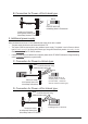
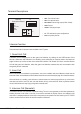
1. Direct lock connection
Use the power of the system to supply for the electronic lock, so that the lock can connect to the Door Station directly,
without a additional power supply for the electronic lock. Note that the Door Station can only output a 12Vdc power,
therefore the kind of lock used is limited.
• The rated power of the lock must be less than 12Vdc 300mA when using direct lock connection method.
• The GND must connect to the negative of the lock, and the COM connect to the positive .
• Jumper set to 12 position for PowertoUnlock safety type; set to 23 position for Poweroffto Unlock type(in
this case the Unlock Relay mode should be set to Normally Closed on DT CONFIG software)
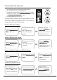
• The 5th bit of the DIP switches is for the unlocking time setting, it's set to off by default, for 1 second unloking
time. If set this bit to on, the unlocking time is 5 seconds.
• If different unlocking time is needed to be congured, the DT CONFIG software can be used to change the
Unlock Timing on the Parameter tab(see the program section).
1 2 3 4 5 6
ON
DIPS
JP_LK
12V 300mA
DIPS-5: default set to off,
unlocking time is 1 second.
(In most cases, 1 second is
work for Power-to-Unlock type)
Jumper set to 1-2 position
+
-
+12V
LK - (GND)
LK+(COM)
N.O.
EB+
EB -
1
2
3
A. Connection for PowertoUnlock type:
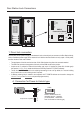
Door Station Lock Connections
1 2 3 4 5 6
ON
L1
+12V
T/R -
T/R+
LK - (GND)
CN-LK JP-LK
RS-485
SET
PA
PB
BUS
LK+(COM)
N.O.
EB+
EB -
1
2
3
L2
1 2 3 4 5 6
ON
L1
+12V
T/R -
T/R+
LK - (GND)
CN-LK
RS-485
SET
PA
PB
BUS
LK+(COM)
N.O.
EB+
EB -
1
2
3
L2
DMR11
Connection Board