2N® Helios IP Safety Emergency IP Intercom Installation Manual Version 2.1 www.2n.
The 2N TELEKOMUNIKACE a.s. is a Czech manufacturer and supplier of telecommunications equipment. The product family developed by 2N TELEKOMUNIKACE a.s. includes GSM gateways, private branch exchanges (PBX), and door and lift communicators. 2N TELEKOMUNIKACE a.s. has been ranked among the Czech top companies for years and represented a symbol of stability and prosperity on the telecommunications market for almost two decades.
Content 1. Product Overview . . . . . . . . . . . . . . . . . . . . . . . . . . . . . . . . . . 4 1.1 Components and Associated Products . . . . . . . . . . . . . . . . . . . . . . . . . . . . . . . 6 1.2 Terms and Symbols . . . . . . . . . . . . . . . . . . . . . . . . . . . . . . . . . . . . . . . . . . . . . . 9 2. Description and Installation . . . . . . . . . . . . . . . . . . . . . . . . . . 10 2.1 Before You Start . . . . . . . . . . . . . . . . . . . . . . . . . . . . . . . . . . . . . . . . . . .
1. Product Overview Here is what you can find in this section: 1.1 Components and Associated Products 1.2 Terms and Symbols Basic Features 2N® Helios IP Safety is a highly resistant and reliable IP door access intercom provided with a lot of useful above-standard functions. Supporting the SIP standard and being compatible with the leading IP PBX and telephone suppliers, 2N® Helios IP Safety can make use of all VoIP services.
2N® Helios IP Safety can also be provided with RFID card reader modules. 2N® Helios IP Safety is very easy to install. All you have to do is connect the system into your LAN via a network cable and feed it from a 12 V power supply or your PoE supporting LAN. Configure 2N® Helios IP Safety using your PC via any web browser. Use the IP Manager to manage extensive 2N® Helios IP Safety systems easily and quickly.
1.1 Components and Associated Products Basic Units Part No. 9152101 1 button Part No. 9152101W 1 button, 10 W loudspeaker, IP69K 2N® Helios IP Safety is designed for outdoor applications and requires no additional roof. W-including Part Nos. are intended for WAP pressure cleaning and extremely noisy environments (such as highways, etc.). 2N® Helios IP Safety units can wall mounted without requiring any additional accessories.
Mounting Accessories Part No. 9152000 Mounting frame orange Aluminum Part No. 9151001 Brick flush mounting box Stainless steel Part No. 9151002 Plasterboard flush mounting box VoIP Telephones Part No. 91378351 Grandstream GXV3140 VoIP video telephone Part No. 91378354 Grandstream GXV3175 VoIP telephone Electric Locks Part No. 932070E BEFO 1211 12 V / 600 mA 2N® TELEKOMUNIKACE a.s., www.2n.cz Part No. 932080E BEFO 1221with momentum pin Part No.
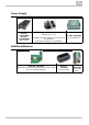
Power Supply Part No. 91378100E Part No. 91378100US PoE injector Part No. 91341481E Adapter 12 V / 2 A A stabilised power supply has to be used if the Ethernet (PoE) power supply is not available. Part No. 932928E 12 V transformer Additional Modules Part No. 9151010 Additional switch with normally open/closed contact and 12 V switched output. 2N® TELEKOMUNIKACE a.s., www.2n.cz Part No. 9159010 Security Relay Part No.
1.2 Terms and Symbols The following symbols and pictograms are used in the manual: Safety Always abide by this information to prevent persons from injury. Warning Always abide by this information to prevent damage to the device. Caution Important information for system functionality. Tip Useful information for quick and efficient functionality. Note Routines or advice for efficient use of the device. 2N® TELEKOMUNIKACE a.s., www.2n.
2. Description and Installation Here is what you can find in this section: 2.1 2.2 2.3 2.4 Before You Start Mechanical Installation Electric Installation Extending Module Connection 2N® TELEKOMUNIKACE a.s., www.2n.
2.1 Before You Start Product Completeness Check Before you start please check the contents of your 2N® Helios IP Safety delivery: 1× 1× 1× 1× 1× 1× 4× 4× 2N® Helios IP Safety Torx 10 / Torx 20 double-ended wrench spare sealing for big bushing for a thick cable, one hole big blank with nut this manual mounting template screws (5 × 80) mm "intelligent" (8 × 50) mm dowels Note Mounting frame is not included – it is sold separately as order no. 9152000.
2.2 Mechanical Installation Mounting Type Overview Refer below for a list of mounting types and necessary components. Flush mounting – classic bricks What You Need: A precisely cut hole or, optionally, the brick flush mounting box, Part No.
Flush mounting – hollow bricks What You Need: Brick flush mounting box, Part No. 9151001 Hole: (132 × 223 × 83) mm Flush mounting – plasterboard wall What You Need: Plasterboard flush mounting box, Part No. 9151002 Hole: (118 × 235) mm Wall mounting (concrete and steel structures, entry barrier columns, etc.) What You Need: Just your 2N® Helios IP Safety unit 2N® TELEKOMUNIKACE a.s., www.2n.
Caution The warranty does not apply to the product defects and failures arisen as a result of improper mounting (in contradiction herewith). The manufacturer is neither liable for damages caused by theft within an area that is accessible after the attached electric lock is switched. The product is not designed as a burglar protection device except when used in combination with a standard lock, which has the security function.
Flush Mounting – Classic Bricks If you use the brick flush mounting box, follow the instructions included in the box. If you do not use the mounting box, follow the instructions below: 1. Make a hole using the template. Suppose that all the required cables have been carried into the hole. 2. Unpack the frame, put the intercom inside and place the set onto the hole to make sure that the hole is deep enough and the uneven edge is perfectly covered with the frame. 3.
Flush Mounting – Thermally Insulated Wall Cut out the thermal insulation layer using the template (the same as for classic brick wall). Caution The hole depth depends on the insulation layer thickness. If the insulation layer is rather thick, you may need longer screws! If there are hollow bricks under the insulation, make sure that your screws pass through the whole dowel (50 mm) and fix the dowel reliably. Make sure that the dowel holes have the required diameter.
Flush Mounting – Hollow Bricks Suppose you intend to install your 2N® Helios IP Safety unit into a wall made of hollow bricks. Note that the external side of the bricks gets damaged by cutting and the dowels cannot practically be fixed into the thin internal part of the bricks. Therefore, use the brick flush mounting box and follow the instructions included therein. Flush Mounting – Plasterboard Use the plasterboard flush mounting box and follow the instructions included therein. 2N® TELEKOMUNIKACE a.s.
Wall Mounting Wall (surface) mounting is used where flush mounting is inapplicable (in concrete and steel structures, entry barrier columns, etc.). The frame is not used. Caution Wall mounting may be a problem where vandals may destroy the unit (in public garages, e.g.). Therefore, use steel fixing elements instead of the dowels and screws included in the delivery. Be sure to insert plugs into unused bushing holes to avoid water leakage during facade cleaning, for example.
1. Select the 2N® Helios IP Safety position with respect to the supply cables. Where the cables are installed inside a structure or wall, use the hole at the intercom bottom. 2. Drill holes of the depth of 70 mm for dowels in the wall as shown in the figure. Push or hammer the enclosed dowels into the drilled holes. Use some suitable building adhesive if the dowels are too loose. Use fixing elements of your own for steel structure surface mounting (metric screws + nuts, e.g.). 3.
How to Pull a RJ-45 Terminated Cable through a Bushing 1. Unscrew the big bushing nut completely. 2. Remove the sealing including the cover from the bushing. Cut either of the components as shown in the figures. 3. Put the bushing nut on the cable and insert the sealing. 4. Replace the cover onto the sealing. 2N® TELEKOMUNIKACE a.s., www.2n.
5. Pull the cable connector though the bushing body into the intercom and clip it into the motherboard connector. 6. Move the sealing including the cover along the cable as far as the bushing body, or add a plug if necessary. 7. Replace and tighten the nut. 2N® TELEKOMUNIKACE a.s., www.2n.
2N® TELEKOMUNIKACE a.s., www.2n.
2.3 Electric Installation This subsection describes how to connect 2N® Helios IP Safety into your Local Area Network (LAN) and how to connect supply voltage and the electric lock. PCB Connectors Picture shows the lay-out of connectors on the 2N® Helios IP Safety printed circuit board (PCB). Cables, accessories and other system components are connected to connectors X1 through X22. Figure: 2N® Helios IP Safety Connectors, PCB Version 555v2 2N® TELEKOMUNIKACE a.s., www.2n.
Figure: 2N® Helios IP Safety Connectors, PCB Version 555v3 Description of Connectors: X1 – Loudspeaker X4 – Camera module X5 – Button 1 SW1 – Reset button (555v3 version only) X6 – Configuration jumpers X8 – Extending module (RFID card reader or additional switch) X10 – Buttons 1 through 4 X11 – LAN X12 – Servicing connector X13 – Keypad module X15 – Left-hand microphone X16 – Right-hand microphone X17 – Relay NO and NC contact X18 – 12 V / 700 mA switched output 2N® TELEKOMUNIKACE a.s., www.2n.
X19 – 12 V / 1 A DC power input LED1/2 – System status indicators LED3 – LAN connection activity indicator LAN Connection 2N® Helios IP Safety is connected to the LAN via a RJ-45 terminated (connector X11) UTP/STP cable (of category Cat 5e or higher). The system is equipped with the Auto-MDIX function and so both the straight and crossed cable versions can be used.
Factory Default Resetting (PCB version 555v2) 1. Disconnect the device from the power supply. 2. Move the short-circuit jumper on connector X6 into the Default setup position. Configuration jumpers (X6) are located in the right-hand upper corner of the PCB. 3. Reconnect the power supply and wait for a start signalling sound. 4. Disconnect the device from the power supply. 5. Move the short-circuit jumper on connector X6 into the Normal operation position. 6. Reconnect the power supply.
2.4 Extending Module Connection 2N® Helios IP Safety allows to connect following extending modules: Additional Switch Security Relay Additional Switch The Additional Switch (Part No. 9151010) is used for extending the number of outputs. This extending module is intended for mounting into the 2N® Helios IP Safety main unit and is compatible with the basic units with Part No. 915210xxxxx.
Module settings: Refer to the 2N® Helios IP Configuration Manual for details. 2N® TELEKOMUNIKACE a.s., www.2n.
Connection: Security Relay The Security Relay (Part No. 9159010) is used for enhancing security between the intercom and the connected electric lock. The 2N® Helios IP Security Relay is designed for any 2N® Helios IP intercom model with firmware versions 1.15 and higher. It significantly enhances security of the connected electric lock as it prevents lock opening by forced intercom tampering.
Installation: Install the 2N® Helios IP Security Relay onto a two-wire cable between the intercom and the electric lock inside the area to be secured (typically behind the door). The device is powered and controlled via this two-wire cable and so can be added to an existing installation. Thanks to its compact dimensions, the device can be installed into a standard mounting box.
Connection: 2N® TELEKOMUNIKACE a.s., www.2n.
3. Function and Use In this section we describe the basic and extending functions of the 2N® Helios IP Safety product. Here is what you can find in this section: 3.1 Configuration 3.2 Maintenance 2N® TELEKOMUNIKACE a.s., www.2n.
3.1 Configuration Use a PC equipped with any web browser to configure 2N® Helios IP Safety : Launch your web browser (Internet Explorer, Firefox, etc.). Enter the IP address of your intercom (http://192.168.1.100/, e.g.). Log in using the Admin user name and 2n password. You have to know the IP address of your device to log in to the integrated web server. By default, 2N® Helios IP Safety is switched into the dynamic IP address mode, i.e.
IP Address Retrieval Take the following steps to retrieve the 2N® Helios IP Safety IP address: Connect (or, if connected, disconnect and reconnect) 2N® Helios IP Safety to the power supply. Wait for the second sound signal . Press the quick dial button 5 times. 2N® Helios IP Safety will read its IP address. If the address is 0.0.0.0, it means that the intercom has not obtained the IP address from the DHCP server.
Caution The 15 times 1 sequence must be entered within 30 seconds after the first sound signal for security reasons. The inter-digit delay may be 2 s at most. The static IP address mode will be switched into the dynamic IP address mode and vice versa upon restart. 2N® TELEKOMUNIKACE a.s., www.2n.
3.2 Maintenance Cleaning If used frequently, 2N® Helios IP Safety gets dirty. To clean it, use a piece of soft cloth moistened with clean water. We recommend you to obey the following principles while cleaning: Never use aggressive detergents (such as abrasives or strong disinfectants). Use suitable cleaning agents for glass lens cleaning (cleaners for glasses, optic devices screens, etc.). Alcohol-based cleaners may be applied. Clean the device in dry weather in order to make waste water evaporate quickly.
4. Technical Parameters Signalling protocol SIP Buttons Button design: Industrial waterproof, pushbutton, blue backlit Count of buttons: 1 (2 on request) Numerical keypad: (on request) stainless steel, vandal resistant Audio Microphone: 2 integrated microphones Amplifier: 10 W (class D) Loudspeaker: 1 W (optionally 10 W) Volume control: Adjustable with automatic adaptive mode Full duplex: Yes (AEC) Audio stream Protocols: RTP/RTSP Codecs: G.711, G.
Additional switch Optional Includes also tamper switch Passive switch: NO and NC contacts, up to 30 V / 1 A AC/DC Active switch output: 9 up to 13 V DC depending on power supply (PoE: 9 V; adaptor: power supply voltage minus 1 V), max 700 mA Mechanical properties Cover: Robust aluminium cast product Colour: RAL 2004 (orange) Working temperature: −40 °C to 55 °C Working relative humidity: 10 % – 95 % (non-condensing) Storing temperature: −40 °C to 70 °C Dimensions 217 × 109 × 83 mm 242 × 136 × 83 mm incl.
5. Supplementary Information Here is what you can find in this section: 5.1 Troubleshooting 5.2 Directives, Laws and Regulations 5.3 General Instructions and Cautions 2N® TELEKOMUNIKACE a.s., www.2n.
5.1 Troubleshooting For the most frequently asked questions refer to faq.2n.cz. 2N® TELEKOMUNIKACE a.s., www.2n.
5.
FCC NOTE: This equipment has been tested and found to comply with the limits for a Class B digital device, pursuant to part 15 of the FCC Rules. These limits are designed to provide reasonable protection against harmful interference in a residential installation. This equipment generates, uses and can radiate radio frequency energy and, if not installed and used in accordance with the instructions, may cause harmful interference to radio communications.
5.3 General Instructions and Cautions Please read this User Manual carefully before using the product. Follow all instructions and recommendations included herein. Any use of the product that is in contradiction with the instructions provided herein may result in malfunction, damage or destruction of the product.
Electric Waste and Used Battery Pack Handling Do not place used electric devices and battery packs into municipal waste containers. An undue disposal thereof might impair the environment! Deliver your expired electric appliances and battery packs removed from them to dedicated dumpsites or containers or give them back to the dealer or manufacturer for environmental-friendly disposal. The dealer or manufacturer shall take the product back free of charge and without requiring another purchase.
2N TELEKOMUNIKACE a.s. Modřanská 621, 143 01 Prague 4, Czech Republic Phone: +420 261 301 500, Fax: +420 261 301 599 E-mail: sales@2n.cz Web: www.2n.cz EN1788_v2.0.1 2N® TELEKOMUNIKACE a.s., www.2n.