2N® SmartGate UMTS UMTS + GSM gateway User guide Version 1.1.0 www.2n.
The 2N TELEKOMUNIKACE a.s. joint-stock company is a Czech manufacturer and supplier of telecommunications equipment. The product family developed by 2N TELEKOMUNIKACE a.s. includes UMTS/GSM gateways, private branch exchanges (PBX), and door and lift communicators. 2N TELEKOMUNIKACE a.s. has been ranked among the Czech top companies for years and represented a symbol of stability and prosperity on the telecommunications market for almost two decades.
Table of Contents 1. Product Overview ............................................................. 7 1.1 Product Description ................................................................................................... 8 Basic Features ............................................................................................................. 8 Advantages of 2N® SmartGate UMTS use ................................................................... 8 Safety Precautions ..............................
Telephone interface FXO parameters......................................................................... 35 FXS routing table parameters..................................................................................... 38 FXO routing table parameters .................................................................................... 41 UMTS/GSM routing table ........................................................................................... 44 SMS Sending Input Parameters ....................
6.2 Troubleshooting....................................................................................................... 77 6.3 List of Abbreviations................................................................................................ 79 6.4 General Instructions and Cautions ......................................................................... 81 Electric Waste and Used Battery Pack Handling.........................................................
1 1. Product Overview In this section, we introduce the 2N® SmartGate UMTS product, outline its application options and highlight the advantages following from its use. This chapter also includes safety instructions. Here is what you can find in this section: n Product Description n Manual changes description n Abbreviations, Terms and Pictograms Used.
Product Description 1.1 1.1 Product Description Basic Features n The primary purpose of 2N® SmartGate UMTS is to transmit voice between UMTS/GSM network and attached phone terminals. You can connect terminal with FXO interface (trunk line of PBX, phone set, answering machine etc.) to FXS interface on 2N® SmartGate UMTS (connector with phone icon) and terminal with FXS interface (extension line of PBX) to FXO interface on 2N® SmartGate UMTS (connector with crossed out phone icon).
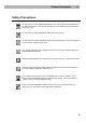
Product Description 1.1 Safety Precautions Do not switch on 2N® SmartGate UMTS in the vicinity of medical apparatuses to avoid interference. The minimum distance of the antenna and pacemakers should be 0.5m. Do not switch on 2N® SmartGate UMTS aboard of a plane. Do not switch on 2N® SmartGate UMTS near petrol stations, chemical facilities or sites where explosives are used. Any mobile telephone use prohibition based on RF energy radiation applies to 2N® SmartGate UMTS too.
Changes 1.2 1.2 Changes Manual Version Amendments to Earlier Versions 1.0.0 The User Manual for SmartGate UMTS. 1.0.1 Corrected errors in text 1.0.2 US version included 1.1.0 Version with module SIM5320 added Caution n n The manufacturer continuously meets customer requirements by improving the firmware. For the latest 2N® SmartGate UMTS processor firmware, programming tool and User Manual see www.2n.cz.
Terms and Symbols Used 1.3 1.3 Terms and Symbols Used Manual Symbols Safety n Always abide by this information to prevent persons from injury. Warning n Always abide by this information to prevent damage to the device. Caution n Important information for system functionality. Tip n Useful information for quick and efficient functionality. Note n Routines or advice for efficient use of the device.
2 2. Description and Installation This section describes the2N® SmartGate UMTS product and its installation.
Description 2.1 2.1 Description Packing of 2N® SmartGate UMTS contains UMTS/GSM gateway in white plastic cover, power supply, antenna and cables for connecting phone interfaces and PC 2N® SmartGate UMTS’s status is indicated by LED diodes on its front side. All possible states are described in the following figure. Power supply Light blue 2N® SmartGate UMTS is powered from the grid. Light yellow 2N® SmartGate UMTS is powered from the battery.
Description 2.1 Telephone Line Tones – Operational Tones The UMTS/GSM gateway sends tones to the telephone line to indicate the line status. The tone frequency is 425 Hz in initial setting. Frequency is programmable; it is possible to set up double frequency tones. Dial tone n continuous or morse A n 2N® SmartGate UMTS is ready to receive dialing. Ringing tone n Only n The called subscriber's telephone is ringing. n The UMTS/GSM network or connected PBX transmits this tone.
Description 2.1 Dialing end signaling n Only n Dialing reception has been terminated. Connection is being established. PIN tone n n Enter the PIN code. n This tone is transmitted upon power up if the PIN has to be entered manually. PUK tone n Enter the PUK code. n n This tone is transmitted upon repeated wrong PIN entering attempts. SIM card is blocked. Telephone Line Tones – Programming Mode Tones confirming/refusing the values entered are transmitted during telephone line based programming.
Before You Start 2.2 2.
Before You Start 2.2 n 2N® SmartGate UMTS is designed for indoor use. It may not be exposed to rain, flowing water, condensed moisture, fog, etc. n 2N® SmartGate UMTS may not be exposed to aggressive gas, acid vapours, solvents, etc. n 2N® SmartGate UMTS is not designed for environments with high vibrations such as means of transport, machine rooms, etc Caution n Check that you have everything needed for 2N® SmartGate UMTS startup (SIM card, analogue phone set or FXO port of PBX, eventually PC etc.
Mounting 2.3 2.3 Mounting External Antenna Connection Screw the antenna cable into the SMA antenna connector. Caution n Tighten the antenna connector gently with your hand – never use wrenches! Note n For the best signal level fix the antenna in vertical position. n Use signal strength indicator to find best place for antenna. SIM Card Installation Slot for SIM card is placed on the connector panel. Insert the SIM card to the slot with contacts oriented to the front panel.
Mounting 2.3 n For backup use only suggested type of accumulators NiMh size AA. Only this type of storage batteries is permitted for use!.When another type of batteries is used, there is a danger of damage of device or even explosion! n The battery should never be placed in municipal waste. Please check local regulations for disposal of batteries.
Telephone line connection 2.4 2.4 Telephone line connection DialThru gateway – basic connection Phone set is normally connected to extension line of PBX. Wire up 2N® SmartGate UMTS between phone set and PBX. Link extension line of PBX to FXO interface and phone set to FXS interface on SmartGate UMTS.
SMS Sending Input Connection 2.5 2.5 SMS Sending Input Connection You have got a special connector for easy connection to SmartGate UMTS. The connector is equipped with screwing clamps to connect wires from a switching contact (device to be monitored). The other connector end can be connected to the respective 2N® SmartGate UMTS panel connector. The input is designed for the contact of relay connected between the input pins. The input is activated by contact closing (pin interconnection).
3 3. Configuration 2N® SmartGate UMTS This section describes configuration of the product 2N® SmartGate UMTS.
2N® SmartGate UMTS parameters configuration 3.1 3.1 2N® SmartGate UMTS parameters configuration PC Connection You have got a USB cable for PC connection. Caution n Make sure that a longer cable works properly to avoid errors at high transmission rates. 2N® SmartGate UMTS Parameter Programming Most of SmartGate UMTS’s parameters have such default values that meet most users’ demands and need not be changed. Usually you have to program routing tables according to 2N® SmartGate UMTS usage.
2N® SmartGate UMTS parameters configuration 3.1 Numeric parameters are programmed using numbers in units included in the parameter description. The step for setting must be respected. For parameters with different setting are values defined in the parameters description (in parenthesis). To cancel any programming step in the programming mode, press a . Having done so, you can hear the refusal tone and can enter a new parameter number. Parameters are saved when the saving tone is transmitted.
2N® SmartGate UMTS parameters configuration 3.1 Installation and setting of SmartGate PCManager (Win7) 1. Connect 2N® SmartGate UMTS to the PC using USB connection. SmartGate must be switched off. 2. After connecting is the virtual serial port in PC installed automatically. I case, that the port doesn’t install automatically and unknown device is detected, install drivers by using file: Drivers/win/CDM20814_Setup.exe. 3. Find the number of virtual port using Device manager.
2N® SmartGate UMTS parameters configuration 3.1 Caution n All tables are filled-in with default values after PCManager start. It is recommended to load data from 2N® SmartGate UMTS before parameters programming and saving. If you only save data after PCManager start, all parameters except the PIN and service password in the 2N® SmartGate UMTS memory will have default values. Caution n The PIN and service password can only be modified either manually or by full initialization.
2N® SmartGate UMTS parameters configuration 3.1 Monitoring Monitoring is active when 2N® SmartGate UMTS is in operation and registered to the UMTS/GSM network. If 2N® SmartGate UMTS is not registered to UMTS/GSM, the USB port is blocked and no monitoring can be made.
2N® SmartGate UMTS parameters configuration 3.1 Caution n The manufacturer responds to clients' requirements with periodical firmware updating. The latest 2N® SmartGate UMTS firmware, PCManager and User Manual are available on www.2n.cz.
Table of Parameters 3.2 3.2 Table of Parameters All programmable parameters are listed in this section. Each parameter is accompanied with the unit used, function number (if avaliable) for programming via a telephone line, description of SmartGate UMTS's behavior, setting options, setting step and default (initialization) value. Numeric parameters must be set in unit listed in the parameter description.
Table of Parameters Setting options: Default setting: 3.2 YES(1)/NO(0) YES Signaling Line reversal indication for call in progress Function No.:110 Select call in progress signaling by telephone line polarity reversal on FXS interface. There is voltage of reversed polarity on the telephone line during the whole call. Setting options: YES(1)/NO(0) Default setting: NO Tariff pulse when call starts/ends Function No.: 111 Signaling of call start or end by tariff pulse.
Table of Parameters Dial tone – frequency 1[Hz] Function No.: 3.2 120 Setting of frequency 1 of dial tone. This tone is generated after Off-Hook in case 2N® SmartGate UMTS is ready to accept dialing. Setting options: Setting step: efault setting: 1-3400 Hz 1 HzD 425 Hz Dial tone – frequency 2[Hz] Function No.: 121 Function No.: 122 Setting of frequency 2 of dial tone. Setting options: 1-3400 Hz Setting step: Default setting: 1 Hz 425 Hz Dial tone - cadence Dial tone cadence setting.
Table of Parameters Default setting: 3.2 425 Hz Ringback tone – frequency 2 [Hz] Function No.: 127 Setting of frequency 2 of ringback tone. Setting options: Setting step: Default setting: 1-3400 Hz 1 Hz 425 Hz Ringback tone - cadence Function No.: 128 Ringback tone cadence setting.
Table of Parameters 3.2 Setting options: 25 / 50 Hz-2N® SmartGate UMTS rings with 50 or 25 Hz on FXS interface Default setting: 50 Hz Ringing signal - cadence Function No.: 141 Ringing signal cadency setting. Setting options: 1000/4000 ms (0) - 1 s ring, 4 s pause 400/200/400/2000 ms (1)- 400ms ring, 200ms pause, 400ms ring, 2s pause 1500/3500 ms (2) - 1,5 s ring, 3,5 s pause 2000/4000 ms (3) - 2 s ring, 4 s pause Default setting: 1000/4000 ms CLI transmitting Function No.
Table of Parameters 3.2 Telephone interface FXO parameters Dialing parameters Number of rings before Off-Hook Function No.: 200 If 2N® SmartGate UMTS is programmed as FXO gateway, parameter sets the count of rings before Off-Hook. Setting options: 1-255 Step: Default setting: 1 1 Timeout for dialing end recognize [s] Function No.: 201 If 2N® SmartGate UMTS is programmed as FXO gateway, parameter defines timeout during which 2N® SmartGate UMTS waits for further digits to be dialed.
Table of Parameters Maximal Off-Hook without dialing [s] 3.2 Function No.: 206 Parameter defines maximal time of line Off-Hook before dialing to FXO interface during outgoing call from FXS interface. Set up shorter time then timeout from extension line Off-Hook and dialing receiver disconnection on your PBX. In this case PBX usually changes dial tone to busy tone. If defined timeout passes before dialing, 2N® SmartGate UMTS shortly hangs up, after that Off-hooks again and then dials.
Table of Parameters Setting options: Setting step: efault setting: 3.2 1-3400 Hz 1 HzD 425 Hz Dial tone – frequency 2[Hz] Function No.: 221 Function No.: 222 Setting of frequency 2 of dial tone. Setting options: Setting step: Default setting: 1-3400 Hz 1 Hz 425 Hz Dial tone - cadence Dial tone cadence setting.
Table of Parameters Reception volume 3.2 Function No.: 191 Function No.: 280 See FXS interface parameters. „BabyCall“ – Automatic call BabyCall number If 2N® SmartGate UMTS is programmed as FXO gateway, parameter defines a number to be dialed for the automatic call function. If this item is blank, the function is disabled. If only character ‘#’ is included, after BabyCall timeout elapsed the interfaces FXO and FXS are connected and dialing to PSTN over FXO interface is possible.
Table of Parameters 3.2 n Bar the number to be dialed - the calling subscriber n Route the call to UMTS/GSM network, or to PBX through the FXO interface; n tone; Accelerate connection establishing by knowing the number length for the given prefix; n Accelerate connection establishing by allowing to terminate dialing with a #; n Modify the number to be dialed by removing and/or adding prefix.
Table of Parameters 3.2 Caution! n Configuration using phone line programming (DTMF) is applicable for line ‘Other prefixes’ only. Prefix Function No.: - Dialed number prefix identifying the call type. "Other numbers" line is used for calls with prefixes that are not included in the table. Setting options: Default setting: 0-16 characters (0-9,*,#) blank Call enable Function No.: 391 This parameter allows/bars calls with corresponding prefixes.
Table of Parameters Add 3.2 Function No.: 396 The Add parameter is used for automatic call routing. A defined string (prefix) is added to the beginning of the number to be dialed. Setting options: Default setting: 0-16 characters (0-9,*,#,+) blank Extra tariff Function No.: 397 Pseudo tariff metering setting (tariff is based on call duration) for UMTS/GSM calls. Connected PBX must send tariff metering pulses for FXO calls.
Table of Parameters 3.2 n Accelerate connection establishing by allowing to terminate dialing with a #; n Modify the number to be dialed by removing and/or adding prefix. The principle of table function is the same as in the FXS routing table. The call is controlled according to parameters on the row with dialed number prefix match. Remember to fill in the "Other prefixes" line for a number whose prefix is not found in the table. FXO calls route to Function No.
Table of Parameters Off-Hook FXS line and dial PASSWORD plus Setting options: Default setting: 3.2 to activate the function again. 0-8 characters (0-9) blank Operator for Integra Function No.: 405 In some UMTS/GSM networks you can add to dialed number # character and PBX subscriber number. Subscriber number is displayed on other side together with CLI. This parameter take place when dialed number doesn't contain # character. Common parameter for both FXO and FXS port.
Table of Parameters End with # 3.2 Function No.: 494 This parameter enables to establish the call when a # is received. The # character is removed from the dialed number. If a # should be part of the dialed number, this function cannot be used for the given prefix. Setting options: YES(1)/NO(0) Default setting: NO Remove FunctionNo.: 495 The Remove parameter is used for automatic call routing. A defined count of digits (prefix) is removed from the number beginning.
Table of Parameters FXO line Off-Hook to dial-in timeout [ms] 3.2 Function No.: 501 Timeout between FXS line Off-Hook and automatic dial in according to parameter "Dial in" in the table. Setting options: Setting step: Default setting: 100-25500 ms 100 ms 1000 ms Max. ring time for CallBack Function No.: 502 Parameter sets up a behaviour for CallBack function. You've got 2 options how to use a Callback on the FXS port: Simple CallBack - set up for 0.
Table of Parameters Setting options: Default setting: 3.2 0-16 characters (0-9,*,#,+) blank Substring Function No.: - Parameter is used to make filling CLI prefix easier. If parameter "Substring" > 0, 2N® SmartGate UMTS searches filled prefix as substring of the received CLI, but max. to position given by "Substring" parameter. Positions are counted from zero.
Table of Parameters 3.2 SMS Sending Input Parameters Telephone number for SMS Function No.:600 The telephone number to which an SMS is sent upon SMS input activation. If blank, the function is off. Setting options: Default setting: 0-16 characters (0-9,*,#,+) blank SMS text Function No.: - The SMS text to be sent to the preset telephone number. If the SMS text is blank, SMS with signal strength is sent.
Table of Parameters 3.2 Setting options: -According to provider (0) - depending on how the function is selected in the UMTS/GSM network -Activation (1) - ID is not sent. -Suppression (2) - ID is always sent. Default setting: According to provider Roaming enable/disable Function No.: 702 You can make 2N® SmartGate UMTS work even if it is registered to a foreign UMTS/GSM network.
Table of Parameters 3.2 ATTENTION - find out if you have to pay for this function. Every check can lower your credit. Setting options: Default setting: 0-8 characters (0-9,*,#,+) blank Minimal credit Function No.: 712 Set minimal credit value to send warning SMS "LOW CREDIT". If credit is lower then given value, warning SMS is send after every credit check, until you recharge your SIM card. Setting options: Step: Default setting: 0-999 1 0 Credit value position in received SMS Function No.
Table of Parameters UMTS/GSM operator lock 3.2 Function No.: - Refer to GSM & SIM Parameters. Time period for GGMC SMS [h] Function No.:970 Time interval for GGMC SMS sending. GGMC = GSM Gateway Monitoring Centre. The "0" setting means that the function is disabled. Setting options: Step: Default setting: 0-255 h 1h 0 Telephone number for service SMS Function No.:714 Telephone number for service SMS. The number is common for GGMC SMS and "LOW CREDIT" SMS on prepaid SIM cards.
Table of Parameters Global initialization 3.2 Function No.: 999 Initialization of all 2N® SmartGate UMTS parameters including the PIN and service password. Only Global initialization can be done by phone line programming. As parameter must be used. This operation of this function service password followed by isn’t followed by confirmation tone. Successful setting is followed by pause (aprox.10s), during this time period is performed reset of configuration memory. Than is the gateway restarted.
4 4. Function and Use This section describes the basic and extending functions of the product 2N® SmartGate UMTS . Here is what you can find in this section: n Voice function n SMS Sending Input n USB – monitoring, internet, SMS n SIM Card PIN protection.
Voice function 4.1 4.1 Voice function Outgoing and incoming call establishing procedures is for illustration described for analog phone connected to FXS interface and extension line of PBX connected to FXO interface on SmartGate UMTS. In case of other equipment connection, please check SmartGate UMTS’s function by connecting a phone.
Voice function 4.1 4. Hang up to terminate the call. The Line LED goes off. If the called subscriber hangs up first, you can hear the busy tone. Incoming call on FXO interface 1. 2N® SmartGate UMTS detects a ringing signal and immediately interconnects it to FXS interface – the phone starts to ring. 2. The CLIP transmitting must provide connected PBX. 3. If you hook off the phone the call is established.
Voice function 4.1 3. The UMTS/GSM subscriber hears the ringing tone from PBX if the automatic dial in function was applied, if not he hears dial tone from PBX and he can dial required extension himself. 4. The call termination is the same as in case of outgoing call. Gateway for trunk line of PBX Outgoing and incoming call establishing procedures is for illustration described for analog phone connected to FXS interface.
Voice function 4.1 Automatic Call ("BabyCall") If the BabyCall function is enabled on FXS interface, a pre-programmed timeout is counted down after off-hook. If you don’t start dialing within this timeout, 2N® SmartGate UMTS signals dialing end and starts to establish a call to the preprogrammed number using UMTS/GSM network automatically – from now 2N® SmartGate UMTS behaves as if a standard outgoing call to UMTS/GSM had been established.
Voice function 4.1 Configuration of network services 2N® SmartGate UMTS provides some of network services to improve possibility of usage. The configuration is done by standard Star-Hash codes you can know from mobile phones. To configure these services: 1. Hook off the telephone, you can hear the dial tone. 2. Enter the Star-Hash code described below. 3. Wait for information tone. You may wait about 3 seconds. 4. Hook on.
Voice function 4.1 Call forwarding unconditional If activated, incoming calls will be always forwarded to the configured telephone number. Activation for all call types: Activation for selected call type: Deactivation: Status check: Call forwarding if busy If activated, incoming calls will be forwarded to the configured telephone number if there is call in progress on SmartGate UMTS.
Voice function 4.1 Activation for all call types and specified delay time: Activation for selected call type and specified delay time: Deactivation: Status check: Call forwarding if not accessible If activated, incoming calls will be forwarded to the configured telephone number if your 2N® SmartGate UMTS is not accessible in the UMTS/GSM network.
Voice function 4.1 Call hold Check if your network supports the service before you use it. This service relates to Call waiting described in 0. If there is call waiting on the line, you have more possibilities what to do.
SMS Sending Input 4.2 4.2 SMS Sending Input This universal input is intended especially for reporting alarm or error statuses of any equipment provided with the appropriate contact (a relay contact, e.g.). By activating this input (electric input pin interconnection) you send one SMS to one pre-programmed telephone number. Caution n Do not use in life-supporting or property-protection applications because of the character of SMS service and 2N® SmartGate UMTS equipment.
Data connection using USB 4.3 4.3 Data connection using USB 2N® SmartGate UMTS can be used as high speed wireless modem to connect your PC to internet. Technology HSDPA, UMTS. EDGE or GPRS are supported. Connection to internet–Sierra Wireless module version For Internet connection management is used program AirCard Watcher. Internet connection setting 1. Install program ‘Watcher_Generic_B2849.msi’ from CD.
Data connection using USB 4.3 APN 6. Confirm the saving of your profile (OK). You will be connected to internet automatically. SMS sending and receiving Program AirCard Watcher supports sending and receiving SMS – select menu SMS Express. Simple SMS application is activated. Connection to internet – Simcom module version USB driver installation For communication over USB port of EasyGate is necessary to install USB driver.
Data connection using USB 4.3 APN name must be received from your mobile provider, in example is the APN of T-Mobile Czech republic used. Network connection setting · Ask you mobile provider for Internet connection instructions because they can be different for each provider (especially the telephone number to be dialed, eventually Username, Keyword, DNS, etc.). Set phone connection in your PC using Network connection setting and select appropriate modem.
SIM Card PIN protection 4.4 4.4 SIM Card PIN protection If a SIM card is PIN-protected and the PIN is not programmed in SmartGate UMTS, UMTS/GSM LED indicates the state and the PIN tone is transmitted on telephone line. PIN Entering by PCManager Like other parameters, the PIN code can be entered using a PC programming tool. The PIN will be entered automatically upon every 2N® SmartGate UMTS power up. PIN Entering via Telephone Line PIN entering via a telephone line connected to FXS interface: 1.
SIM Card PIN protection 4.4 Automatic PIN Entering You need not enter the PIN upon power up if it is stored in 2N® SmartGate UMTS – it is entered automatically. This function is useful in case of power failure; 2N® SmartGate UMTS is operable in a short time after power recovery without any intervention by the operating staff. Caution! n One PIN entering option is exhausted by the attempt to enter the PIN automatically upon SIM card or PIN change.
5 5. Technical parameters This section describes the technical parameters of the product 2N® SmartGate UMTS.
Technical Parameters 5.1 5.
Technical Parameters SIM card 5.
Technical Parameters 5.1 Power Supply DC power supply 10 to 16 V DC (accumulator 12V) 12V consumption Supply connector Standby 100 mA Call/data max. 500 mA DC Jack 5,5/2,1 mm positive to center Power source must meet the criteria for SELV standard Battery backup (optional) Accumulator type Charging cell NiMh size AA Number of pieces 4 Power consumption batteries from Standby Call/data Charging current 300 mA max. 1200 mA Typ.
Technical Parameters 5.1 Telephone Interface FXO (for PBX extension line) Interface type 2-wire analog, FXO Telephone connector type RJ 12, 6/2 Line impedance Zr (TBR21) or 600 W (According to model of Gateway) On-hook DC resistance 1 MW Off-hook line current 10 - 65 mA Off-hook line voltage (typ.) 4,5 V for 25 mA Dial tone frequency adjustable, default 425 Hz Dialing type tone (DTMF) Ringing voltage Min.
Technical Parameters 5.
6 6. Supplementary Information This section describes supplementary information of the product 2N® SmartGate UMTS. Here is what you can find in this section: n Regulations and directives n Troubleshooting n List of Abbreviations n General Instructions and Cautions.
Regulations and directives 6.1 6.
Troubleshooting 6.2 6.2 Troubleshooting For tips for the solution of other potential problems see faq.2n.cz. ´ No LED is on after power up u Check the power supply. ´ All LEDs are on. No call is currently in progress.
Troubleshooting ´ 6.2 2N® SmartGate UMTS does not communicate with PC u Check the serial cable connection. u Check the COM number setting on PC. u Check the COM parameters (1200-115200 bps, 8N1). u 2N® SmartGate UMTS is not registered to UMTS/GSM network. u A dialing or outgoing call establishing process takes place on SmartGate UMTS. u An incoming call is ringing on SmartGate UMTS.
List of Abbreviations 6.3 6.3 List of Abbreviations n APN (Access Point Name) Necessary for the GPRS service. n CLIP (Calling Line Identification Presentation) n CSD (Circuit Switched Data) n COM A PC Serial port. n DTMF (Dual Tone MultiFrequency) Tone dialling. n FSK (Frequency Shift Keying) A transmission protocol using variable signal frequencies for logic level encoding. n FXO An interface electrically identical with a standard telephone (opposite side = FXS interface).
List of Abbreviations 6.3 n SMS (Short Message Service) A term for the system and one unit (message). n SW Software. n TTL (Transistor-Transistor Logic) A standard digital technology defining voltage for levels 0 and 1.
General Instructions and Cautions 6.4 6.4 General Instructions and Cautions Please read this User Manual carefully before using the product. Follow all instructions and recommendations included herein. Any use of the product that is in contradiction with the instructions provided herein may result in malfunction, damage or destruction of the product.
General Instructions and Cautions 6.4 Electric Waste and Used Battery Pack Handling Do not place used electric devices and battery packs into municipal waste containers. An undue disposal thereof might impair the environment! Deliver your expired electric appliances and battery packs removed therefrom to dedicated dumpsites or containers or give them back to the dealer or manufacturer for environmental-friendly disposal.
2N TELEKOMUNIKACE a.s. Modřanská 621, 143 01 Prague 4, Czech Republic Tel.: +420 261 301 500, Fax: +420 261 301 599 E-mail: sales@2n.cz Web: www.2n.cz 1699v1.1.