
Manual


Description
2.1
14
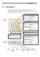
2.1 Description
Packing of 2N® SmartGate UMTS contains UMTS/GSM gateway in white plastic cover,
power supply, antenna and cables for connecting phone interfaces and PC
2N
®
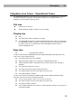
SmartGate UMTS’s status is indicated by LED diodes on its front side. All possible
states are described in the following figure.
Switch
ON/OFF
Power
supply
connector
(DC Jack 2.1
mm)
USB
(USB B)
SIM Telephone line
FXS interface
(RJ 12, 6/2)
Telephone line
FXO interface
(RJ 12, 6/2)
SMS connector
SMS sending input
Figure 2.2
2N
®
SmartGate
UMTS Connectors
Figure 2.1
2N
®
SmartGate
UMTS LED indicators
Light blue 2N® SmartGate UMTS is
powered from the grid.
Light yellow 2N® SmartGate UMTS is
powered from the battery.
Flashes 1x in 2s HW error, contact the
manufacturer
No light HW error, contact the
manufacturer
Power supply
Light blue Registered to UMTS/GSM
Flashes:
1x in 1s not registered, SIM card inserted
1x in 3s not registered,
SIM card not inserted
4x quickly enter your PIN
8x quickly enter your PUK
Quickly continuously
All functions are blocked. Your
SIM doesn’t correspond to the
operator lock.
UMTS/GSM network
No light Standby
Orange for FXS interface:
Flashes quickly line off-hook or ringing
Light call FXS - UMTS/GSM
Green for FXO interface:
Flashes quickly line off-hook or ringing
Light call FXO - UMTS/GSM
Alternately oragne and green:
Quickly ringing from FXO is connected to
FXS interface
Slowly call FXS - FXO
Telephone line
No light no data transmission
Light yellow data transmission
Data
device connected to PC
Steady state – signalization of signal
strenght
FXS line off hook – signalization of
battery state (battery backup type only)
Signal strength/baterry indicator