2N® Helios IP IP Intercom Configuration Manual Firmware Version 2.8 2.8.1 www.2n.
The 2N TELEKOMUNIKACE a.s. is a Czech manufacturer and supplier of telecommunications equipment. The product family developed by 2N TELEKOMUNIKACE a.s. includes GSM gateways, private branch exchanges (PBX), and door and lift communicators. 2N TELEKOMUNIKACE a.s. has been ranked among the Czech top companies for years and represented a symbol of stability and prosperity on the telecommunications market for almost two decades.
Content 1. Product Overview . . . . . . . . . . . . . . . . . . . . . . . . . . . . . . . . . . 4 2. Express Wizard for Basic Settings . . . . . . . . . . . . . . . . . . . . 6 3. Model Differences and Function Licensing . . . . . . . . . . . . . 11 4. Signalling of Operational Statuses . . . . . . . . . . . . . . . . . . . . 14 5. Intercom Configuration . . . . . . . . . . . . . . . . . . . . . . . . . . . . . 16 5.1 Status . . . . . . . . . . . . . . . . . . . . . . . . . . . . . . . . . . . . . . . . .
1. Product Overview The 2N® Helios IP door intercoms can smartly replace traditional doorbell push-button speakerphone panels and all wiring, bells and home intercom installations in buildings with structured cabling. The intercoms provide more advanced and wider services than standard home phones. The installation is very easy, all you need is connect the intercom to the other LAN elements using a UTP cable and set necessary parameters.
Safety Always abide by this information to prevent persons from injury. Warning Always abide by this information to prevent damage to the device. Caution Important information for system functionality. Tip Useful information for quick and efficient functionality. Note Routines or advice for efficient use of the device. 2N® TELEKOMUNIKACE a.s., www.2n.
2. Express Wizard for Basic Settings LAN Connection Setting You have to know the intercom configuration interface address to connect to the LAN successfully. Automatic IP address retrieval from the DHCP server is set by default in the 2N® Helios IP intercoms. Thus, if connected to a network in which a DHCP server configured to assign IP addresses to all new devices is available, the intercom will obtain an IP address from the DHCP server.
Firmware Update We also recommend you to update your intercom firmware upon the first login to the intercom. Refer to www.2n.cz for the latest firmware version. Press the Update Firmware button in the System / Maintenance menu to upload firmware. The intercom will get restarted upon upload and only then the updating process will be complete. The process takes about 30 seconds.
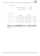
Proxy address – set the SIP Proxy IP address or domain name. Registrar address – set the SIP Registrar IP address or domain name. The SIP Proxy and SIP Registrar addresses are usually identical. Registration enabled – enable intercom registration with the set SIP Registrar. If your SIP server requires authentication of terminal equipment, enter the following parameters: Password – enter the password for intercom authentication.
You can also use the 2N® Helios IP intercom with one or more IP phones without a SIP server. Use the Direct SIP Call for outgoing calls and enter the called phone SIP address (sip:phone_number@phone_ip_address) instead of the phone number. Electric Lock Switching Settings An electric lock can be attached to the 2N® Helios IP intercoms and controlled by a code from the intercom numeric keypad, or a code from the IP phone keypad during a call.
Enable the switch in the Switch Enabled parameter in the Hardware / Switches / Switch 1 tab, set the Controlled Output to the intercom output to which the electric door lock is connected. Now set one or more activation codes for the electric door lock switching. 2N® TELEKOMUNIKACE a.s., www.2n.
3. Model Differences and Function Licensing This manual is valid for all members of the 2N® Helios IP family and so some features described herein are only available in selected 2N® Helios IP models or need to be activated with a valid licence key. This section provides a short list of differences between the models and licences which affect the configuration options. If a function is not available in all the models, there is a note in the respective subsection and reference to this section.
2N® Helios IP Property/Model Verso Vario Force Safety Uni Basic unit button count 1 1, 3 or 6 1, 2 or 4 Button extenders up to 145 up to 48 no Numeric keypad optional Digital input yes optional Adaptive volume control yes no yes Amplifier power output 2W 150 mW 1W Extended amplifier power output (10 W) no yes no no Tamper switch optional no optional yes no Phone Book position count 1999 2 16 User deputy yes no yes User activation/deactivation yes no yes Controll
User sounds Enhanced Enhanced Enhanced Enhanced Gold Audio Video Integration Security (Profi) • • Automatic audio test • Property/Licence • Audio/video streaming (RTSP Server) • • External IP camera support • • ONVIF support • • Extended switch setting options • • HTTP switch control • • Automation functions • • E-mail sending (SMTP Client) • • Automatic update (TFTP/HTTP Client) • • 802.1x support • • SIPS (TLS) support • • 2N® TELEKOMUNIKACE a.s., www.2n.
4. Signalling of Operational Statuses 2N® Helios IP generates sounds to signal switching and changes of operational statuses. Each status change is assigned a different type of tone. See the table below for the list of signals. Note Signalling of some of the above mentioned statuses can be modified; refer to the User Sounds subsection. Tone Meaning User activated This tone signals entering of the user activation code. The activation code is used for user (Phone Book position) activation.
Call prolongation confirmation signalling Calls are time-limited in 2N® Helios IP for security reasons (protection against blocking). Refer to the Miscellaneous subsection for details. Internal application launched The internal application is launched upon 2N® Helios IP power up or restart. A successful launch is signalled by this tone combination. Connected to LAN, IP address received 2N® Helios IP logs in upon the internal application launch. A successful LAN login is signalled by this tone combination.
5. Intercom Configuration 2N® TELEKOMUNIKACE a.s., www.2n.
Start Screen The start screen is an introductory overview screen displayed upon login to the intercom web interface. Use the back arrow in the left-hand upper corner of the following web interface pages to return to this screen anytime. The screen header includes the intercom name (refer to the Display Name parameter in the Services / Phone / SIP menu). Select the web interface language with the CZ and EN buttons. Press the Log out button in the right-hand upper corner to log out.
Services Phone – telephone and SIP connection settings Streaming – audio/video streaming settings (ONVIF, RTSP, Multicast, etc.) E-Mail – E-mail sending and SMTP connection settings Automation – flexible intercom settings according to the user's requirements User Sounds – user sound settings and upload Web Server – web server and access password settings Audio Test – automatic audio test settings System Network – LAN connection settings, 802.
5.1 Status The Status menu provides clear status and other essential information on the intercom. The menu is divided into three tabs: Device, Services and Licence. Device The Device tab displays basic information on the intercom model, its features, firmware and bootloader versions and so on. Services The Services tab displays the status of the network interface and selected services. 2N® TELEKOMUNIKACE a.s., www.2n.
Licence The Licence tab displays the list of licensed functions of the intercom including their current availability (on the basis of a valid licence key entered in the System | Licence menu). 2N® TELEKOMUNIKACE a.s., www.2n.
5.2 Directory Here is what you can find in this subsection: 5.2.1 Phone Book 5.2.2 Time Profiles 5.2.3 Access Cards 2N® TELEKOMUNIKACE a.s., www.2n.
5.2.1 Phone Book The Phone Book is one of the crucial parts of the intercom configuration. It contains user information relevant for such intercom functions as quick dialling, RFID card/code door unlocking, missed call e-mails and so on. The Phone Book is arranged as a table with up to 1999 positions (depending on the particular 2N® Helios IP model): typically, each user is assigned just one position.
higher positions (from position 100 up, e.g.) with data on the users to be included in the public user list. Then select the users to be accessible by quick dialling and copy their phone numbers to the lower Phone Book positions corresponding to the quick dial buttons. Refer to the Directory / Phone Book menu for the Phone Book settings. Use the navigation panel for selecting the Phone Book positions easily and arrows for scrolling pages. Or, you can enter the position number and push quickly.
You can assign up to three user phone numbers to each Phone Book position. In case the user is inaccessible on one number, the following number will be dialled after a ringing timeout. Enable the Parallel call to following number to enable dialling multiple numbers simultaneously. The phone number validity can also be time profile-limited. Phone number – enter the phone number of the station to which the call shall be routed. Enter the address sip:[user_id@]domain[:port] for Direct SIP calling, e.g.
address as follows: ip_address[: port1][:port2]. The port1 and port2 parameters are optional and are used in case there is Network Address Translation (NAT) between the PC and intercom and the addresses have to comply with the router or another NAT-executing device. The port1 (default value: 8003) parameter defines the destination port for the UDP messages sent to 2N® Helios IP Eye. The port2 (default value: 80) parameter defines the destination port for the 2N® Helios IP Eye – intercom HTTP communication.
Each user can be assigned a private switch activation code. The user switch codes can be arbitrarily combined with the universal switch codes defined in the Hardware | Switches menu. If the codes are identical with the codes already defined in the intercom configuration, the mark will appear at the colliding codes. Code – set a private user switch activation code: up to 16 characters including digits 0–9 only. Time profile – assign a time profile to the switch code to define the code validity.
5.2.2 Time Profiles Such intercom functions as outgoing calls and RFID card/numeric code access, for example, can be time-limited by being assigned a time profile.
List of Parameters Profile name – enter a profile name. This parameter is optional and helps you find items in the time profile list and select profiles in the switch, card and phone number settings more easily. This parameter helps you set time profiles within a week period. A profile is active when it matches the set intervals. Make sure that the real time settings are correct (refer to the Date and Time subsection) to make this function work properly.
Profile activation code – set the profile activation code: 16 characters including digits 0–9 only. If the activation code is the only code defined or the activation and deactivation codes are identical, then the activation code is used both for profile activation and deactivation. Profile deactivation code – set the profile deactivation code: 16 characters including digits 0–9 only. Profile current state – select the current state of the user. 2N® TELEKOMUNIKACE a.s., www.2n.
5.2.3 Access Cards Each intercom user can be assigned one or more access RFID cards. Typically, the card ID is included in the Phone Book together with such user data as phone numbers, E-mail address and so on. Or, you can define the RFID cards in the Installed Cards list, which defines a limited number of unassigned cards reserved for visitors, for example. You can manage – add, remove and modify items – the list of installed cards manually via the intercom configuration interface.
the Records. Double-click to select the card ID and push CTRL+C. Now that you have the card ID in your box, you can insert it with CTRL+V in any intercom setting field. Having been read, the card ID is compared with the intercom card database. If the card ID matches any of the cards in the database, the appropriate action will be executed: switch activation (door unlocking, etc.).
and helps you find the card list items more easily without affecting the intercom function. Records The Records tab displays the last 10 records on applied cards. Each record includes the card tapping time, card ID and type and description details (validity, card owner, etc.). 2N® TELEKOMUNIKACE a.s., www.2n.
5.3 Hardware Here is what you can find in this section: 5.3.1 5.3.2 5.3.3 5.3.4 5.3.5 5.3.6 5.3.7 5.3.8 Switches Speaker Microphone Camera Keyboard Display Card Reader Extenders 2N® TELEKOMUNIKACE a.s., www.2n.
5.3.1 Switches Switches provide a very flexible and efficient control of such intercom peripherals as electric door locks, lighting, additional ringing signalling, and so on. 2N® Helios IP allo ws you to configure up to 4 (depending on model types) independent all-purpose switches. A switch can be activated: by entering the valid code via the intercom numeric keypad or receiving a DTMF sequence during a call. by tapping a valid RFID card on the reader.
List of Parameters Switch enabled – enable/disable the switch globally. When disabled, the switch cannot be activated by any of the available codes (including user switch codes), by a call or quick dial button. Switch mode – set the monostable/bistable mode for the switch. The switch is switched off after a timeout in the monostable mode, and switched on with the first activation and off with the next activation in the bistable mode. Switch-on duration – set the switch-on time for a monostable switch.
Note 2N® Helios IP Vario – be sure to set the internal power supply and switching relay on the configuration connector. 2N® Helios IP Force – the security relay is connected to the DOOR + and - terminals. The table above includes a list of universal codes that help you activate switches from the phone or intercom keypad. Up to 10 universal codes can be defined for each switch (depending on the particular intercom model). Code – enter a numeric code for the switch.
Activation by quick dial button – assign a quick dial button to the switch. The switch is activated whenever the button is pressed. Sound signalling – set the sound signalling type for switch activation. Choose the Short beep, Long beep (during the whole activation) or a User sound (refer to the User Sounds subsection). Display info – enable/disable signalling of an activated switch on the display.
E.g.: http://192.168.1.50/relay1=off Enable switch control by HTTP – enable the HTTP switch control option. Refer to the Switch Control by HTTP details below. Legacy switch code – enable the option to activate the first-listed switch code from the phone without being confirmed with *. When this box is checked, first code does not require confirmation by *. This setting does not apply to other switch codes listed and to numeric keypad code activation, those must be always confirmed by *.
5.3.2 Speaker All the 2N® Helios IP models are equipped with a speaker or power amplifier output to which an external loudspeaker can be connected. Set the phone call and state signalling volume control in this configuration section. The speaker volume settings are closely associated with the microphone sensitivity parameters as explained below. Set the intercom speaker volume and microphone sensitivity values in the Master volume, Phone call volume and Microphone sensitivity parameters.
Tip If the Speaker volume and Microphone sensitivity values exceed + 12 dB if put together, the sound quality of the intercom-to-phone signal may deteriorate in some cases due to acoustic feedback between the microphone and the speaker depending on the intercom installation site conditions (mounting method, device placement, environment qualities, surrounding noise, etc.).
Audio AGC enabled – enable the automatic gain control of the line signal. Audio volume – set the phone call volume. The volume values are relative against the set master volume. Ringtone volume – set the incoming call signal loudness. Call-progress tone volume – set the dial, ring and busy tone volume. In case the call-progress tones are automatically generated by the PBX, this setting will not be applied. Key beep volume – set the key beep volume.
5.3.3 Microphone Set the microphone and line audio input volume parameters in this intercom configuration section. The microphone volume settings are closely associated with the speaker sensitivity parameters and intercom installation site conditions, which affect the general audio reproduction and recording quality. If you notice a deteriorated audio quality, please read the Speaker subsection carefully too to set the intercom audio parameters on your installation site properly.
Note This setting is available in the line input supporting models only. Default audio input – set the default audio input (microphone, line input or audio module input) for phone calls and audio streaming. Line input gain – set the line input gain independently of the microphone gain setting. 2N® TELEKOMUNIKACE a.s., www.2n.
5.3.4 Camera This menu is only available in the 2N® Helios IP models that are equipped with an internal camera or can be connected to an external camera. The camera signal can be streamed directly into the call via a videophone, sent by E-mail, streamed via ONVIF/RTSP to another device (a video surveillance device, e.g.), or simply HTTP downloaded from the intercom in the JPEG format.
of the IP phone keys in the PTZ mode are as follows: IP phone key * 1 3 2 4 6 8 5 PTZ mode function Enable/disable PTZ Zoom in Zoom out Move cropped display up Move cropped display to the left Move cropped display to the right Move cropped display down Return to initial state Brightness level – set the camera image brightness level. Colour saturation – set the camera image colour saturation. Flickering reduction – set reduction of image flickering caused by artificial light sources (fluorescent lamps, e.
extenders are connected and PoE supply is used). Note This setting is only available in the models equipped with an external analogue camera input. Video input – choose one of the analogue camera inputs. You can change the input by automation via the Action.SetCameraInput during operation. Video standard – set the video standard for the camera connected. Modify the value only if the automatic video standard detection does not work well (Auto value).
5.3.5 Keyboard This configuration section helps you set the numeric keypad and quick dial button functions. 2N® Helios IP allows you to: use the numeric keypad for dialling common phone numbers use the numeric keypad for dialling a Phone Book position use the numeric keypad for entering the access code for door unlocking, e.g.
None – button pressing does not affect the call setup or active call. Hang up – button pressing terminates the call setup or active call. Dial the following – button pressing initiates dialling of the following user number in the Phone Book. This accelerates the dialling process in case the user is inaccessible on some of its phone numbers. Flash – button pressing sends a special DTMF character (FLASH) into the current call, to which the connected PBX can response with the selected action.
Backlight level – set the keypad and button backlight level. Keyboard Mapping The 2N® Helios IP Audio Kit and 2N® Helios IP Video Kit models are equipped with eight terminals for up to 16 external buttons or a keypad. The functions can be set for each button separately. The buttons and their settings are arranged in a matrix of 4 columns x 4 rows; see the figure below. The figure below shows the default button settings.
5.3.6 Display Some 2N® Helios IP Vario models are equipped with a colour display. Configure the display exclusively via the 2N® Helios IP Manager. In this menu, you can only switch the display on/off and set a few parameters. List of Parameters Display enabled – enable/disable the display function. Ad screen activation timeout – set the maximum idle time (i.e.
incidence). 2N® TELEKOMUNIKACE a.s., www.2n.
5.3.7 Card Reader This menu is available in the 2N® Helios IP Vario and 2N® Helios IP Force models only. Configure the 2N® Helios IP Verso card reader in the Extenders menu. The card reader helps you control access to your building effectively using contactless RFID cards. The supported card types depend on the card reader model used. The 2N® Helios IP Vario and 2N® Helios IP Force card readers are equipped with an input/output Wiegand interface. The interface direction is configurable.
Card reader enabled – enable the card reader function. If disabled, the card reader ignores all applied cards. If the card is disabled and the Wiegand interface is OUT, all codes of the used cards are resent to the Wiegand interface. Associated switch – select a switch to be activated whenever a valid card is applied. Accepted HID cards – set the type of HID Prox cards to be accepted by the card reader. The card reader supports just one card type at an instant.
5.3.8 Extenders The 2N® Helios IP Verso intercoms can be enhanced with extending modules connected to the intercom basic unit. The following modules are available: five-button module keypad module Infopanel module card reader module I/O module Wiegand module The modules are chain-like interconnected. Each of the modules has its number depending on the chain position (the first module has number 1). The basic unit is a special type of module and has number 0. You can configure each module separately.
Brightness during day - set the LED brightness percentage value for the day mode. Brightness during night - set the LED brightness percentage value for the night mode. Current brightness - display the current LED brightness value automatically selected according to the ambient daylight level. Poznámka The brightness parameters affect the function, power consumption and general appearance of your device.
Basic Unit Module Configuration Output 1 maximum power - set the maximum load to be connected to the power output available on the basic unit. When the output is active, the consumption of the other modules (backlight level, etc.) can be adjusted automatically in order that the maximum allowed consumption of the intercom cannot be exceeded. Button Module Configuration Button function – assign Phone Book positions to the buttons. 2N® TELEKOMUNIKACE a.s., www.2n.
Keypad Module Configuration No parameters are available to the public at present. Infopanel Module Configuration No parameters are available to the public at present. 2N® TELEKOMUNIKACE a.s., www.2n.
Card Reader Module Configuration Associated switch – set the number of the switch to be activated by tapping of a valid RFID card. Forward to Wiegand output - set a group of Wiegand outputs to which all the received RFID card IDs will be resent. I/O Module Configuration Module name – set the module name for input/output specification in the SetOutput, GetInput and InputChanged objects in 2N® Helios IP Automation. 2N® TELEKOMUNIKACE a.s., www.2n.
Wiegand Module Configuration The Wiegand module is equipped with the input and output Wiegand interfaces, which are mutually independent, have separate settings and can receive and send codes at the same time. The Wiegand input helps you connect such equipment as RFID card readers, biometric readers and so on.
5.4 Services Here is what you can find in this section: 5.4.1 5.4.2 5.4.3 5.4.4 5.4.5 5.4.6 5.4.7 5.4.8 Phone Streaming ONVIF E-Mail Automation User Sounds Web Server Audio Test 2N® TELEKOMUNIKACE a.s., www.2n.
5.4.1 Phone The Phone service is one of the basic functions of the intercom: helps you establish connections with other IP network terminal equipment. The 2N® Helios intercoms support the extended SIP and are compatible with and certified by the leading SIP PBX and terminal equipment manufacturers (CISCO, Avaya, Broadsoft, etc.). The intercom supports up to five parallel calls: 1 outgoing and up to 4 incoming calls.
Explanation of IP Telephony Terms SIP (Session Initiation Protocol) – is a phone call signalling transmission protocol used in IP telephony. It is primarily used for setting up, terminating and forwarding calls between two SIP devices (the intercom and another IP phone in this case). SIP devices can establish connections directly with each other (Direct SIP Call) or, typically, via one or more servers: SIP Proxy and SIP Registrar.
SIP 1 and SIP 2 The 2N® Helios IP intercoms allow two independent SIP accounts (SIP 1 and SIP 2 tabs) to be configured. Thus, the intercom can be registered under two phone numbers, with two different SIP exchanges and so on. Both the SIP accounts process incoming calls equivalently. Outgoing calls are primarily processed by account 1, or, if account 1 is not registered (due to SIP exchange error, e.g.), by account 2.
Proxy address – set the SIP Proxy IP address or domain name. Proxy port – set the SIP Proxy port (typically 5060). Registration enabled – enable intercom registration with the set SIP Registrar. Registrar address – set the SIP Registrar IP address or domain name. Registrar port – set the SIP Registrar port (typically 5060). Registration expires – define the registration expiry, which affects the network and SIP Registrar load by periodically sent registration requirements.
Trusted certificate – specify one of the three sets of certificates issued by certification authorities to verify the SIP server public certificate validity, refer to the Certificates subsection. If none is included, the SIP server public certificate is not verified. User certificate – specify the user certificate and private key to verify the intercom authorisation to communicate with the SIP server. There are three sets of user certificates and private keys, refer to the Certificates subsection.
Ring time limit – set the outgoing call setup and ringing time limit after which the calls shall be automatically terminated. If the calls are routed to the GSM network via GSM gateways, your are advised to set a value higher than 20 s. Call time limit – set the call duration limit after which the call is automatically terminated. The intercom signals termination with a beep 10 s before the call end. Enter any DTMF character into the call (# on your IP phone, e.g.) to extend the call time.
Sending mode – define whether it will be possible to send DTMF during a call by pressing 0 through 9, * and # on the intercom numeric keypad. Set the sending mode for incoming/outgoing/all calls. In-Band (Audio) – enable classic DTMF dual tone sending in the audio band. RTP (RFC-2833) – enable DTMF sending via the RTP according to RFC-2833. SIP INFO (RFC-2976) – enable DTMF sending via SIP INFO messages according to RFC-2976.
Video Codec 1–4 – set the order of video codecs for call setup: H.264, H.263+ or H.263. The order defines the codec priority, i.e. the first codec has the highest priority. Video resolution – set the video resolution for phone calls. Video framerate – set the video frame rate for phone calls. Video bitrate – set the video stream bit rate for phone calls. QoS DSCP value – set the video RTP packet priority in the network. The set 2N® TELEKOMUNIKACE a.s., www.2n.
value is sent in the TOS (Type of Service) field in the IP packet header. Maximum packet size – set the size limit for the video RTP packets to be sent. H.264 payload type (1) – set the payload type for video codec H.264 (packetisation mode 1). Set a value from the range of 96 through 127, or 0 to disable this codec type. H.264 payload type (2) – set the payload type for video codec H.264 (packetisation mode 2). Set a value from the range of 96 through 127, or 0 to disable this codec type. H.
5.4.2 Streaming The 2N® Helios IP intercoms provide several audio/video streaming methods; refer to the table below: Transmission method JPEG/HTTP Description Static JPEG image transmission. Refer to the JPEG tab below. MJPEG/HTTP A series of consecutive JPEG images, the Server Push multipart/x-mixed-replace method. Refer to the JPEG tab below. RTSP + RTP/UDP RTSP with separate RTP/UDP audio and video streams. Supported both for audio (G.711) and video (H.264, H.263, MPEG-2 and MJPEG).
Explanation of Terms RTP (Real-Time Transport Protocol) – is a protocol defining the standard packet format for audio/video transmission via IP networks. 2N® Helios IP employs this protocol for audio/video streaming. The RTP transport protocol is either UDP or also RTSP and HTTP. RTSP (Real-Time Streaming Protocol) – is a network protocol for streaming server control (controls setting up, launching and stopping of audio/video streams).
Set the video stream (video codec type, image resolution, frame rate and bit rate) parameters in the Video section. Or, use the following RTSP Uri and choose a codec type other than the currently set one: a. rtsp://ip_intercom_address/h264_stream b. rtsp://ip_intercom_address/mpeg_stream c. rtsp://ip_intercom_address/mjpeg_stream RTSP server enabled – enable the RTSP server function in the intercom. Audio stream enabled – enable offering of audio stream while establishing connection with the RTSP server.
Video resolution – set the default image resolution for RTSP streaming. Video framerate – set the default video frame rate for RTSP streaming. Video bitrate – set the default video bit rate for RTSP streaming. Video quality - set the video compression level (for MJPEG only) ranging between 10 (low quality, lowest bitrate) and 99 (top quality, highest bitrate). IP address 1–4 – set up to 4 authorised IP addresses from which you can log in to the RTSP server.
or (for MJPEG, HTTP Server Push): http://intercom_ip_address/enu/cameraWxH.jpg?fps=N where W and H specify image resolution (supported resolutions: 160x120, 320x240, 640x480, 176x144, 322x272, 352x288, 1280x960 – for 1MPix camera equipped models only) and N gives the count of snapshots per second (1 through 10). Note The HTTP Server Push method with the multipart/x-mixed-replace contents is not supported by all internet browsers. Test the function in the Firefox browser, for example.
Multicast receiver enabled – enable receiving of RTP packets on the selected multicast address and port. The audio stream received is played during an active call too and the sounds from the two sources get mixed. Receive address – set the multicast IP address to receive multicast RTP packets. Receive port – set the local port to receive multicast RTP packets. Volume – set the received audio stream playing volume.
The intercom supports registration with up to 4 Informacast servers at the same time and setup of up to 6 parallel audio streams. Informacast service enabled - enable the Informacast service on your intercom side. Broadcast enabled - enable the Broadcast command to set up an audio stream sent from the Informacast server to the intercom. Capture enabled - enable the Capture command to set up an audio stream sent from the intercom to the Informacast server.
5.4.3 ONVIF List of Parameters The 2N® Helios IP intercoms are ONVIF compatible and fully implement the ONVIF Profile S. Discovery mode – enable the WS-Discovery function, which allows the other ONVIF clients to search a compatible device in the LAN. Set the parameter to Discoverable to use your intercom as an ONVIF compatible device. User name - set the user name for access to ONVIF. Password - set the password for access to ONVIF.
Note Preset authorisation for ONVIF Username: admin Password: 2n 2N® TELEKOMUNIKACE a.s., www.2n.
5.4.4 E-Mail To inform the intercom users on all missed and/or successfully completed calls, configure 2N® Helios IP to send an E-mail after every call to the called user. You can compile the E-mail subject and message text of your own. If your intercom is equipped with a camera, you can automatically attach one or more snapshots taken during the call or ringing. The intercom sends E-mails to all the users whose valid E-mail addresses are included in the Phone Book.
Server address – set the SMTP server address to which E-mails shall be sent. Server port – specify the SMTP server port. Modify the value only if the SMTP server setting is substandard. The typical SMTP port value is 25. Username – enter a valid username for login if the SMTP server requires authentication, or leave the field empty if not. Password – enter the SMTP server login password. User certificate – specify the user certificate and private key for the intercom – SMTP server communication encryption.
E-Mail Send E-Mail at – set E-mail sending upon outgoing phone calls. The E-Mail is sent when the connection is terminated. The following options are available: Any Outgoing call - an E-mail will be sent upon every outgoing call. Missed Outgoing call - an E-mail will be sent upon every missed outgoing call. Via Automation - no E-mail messages will be sent upon outgoing calls. Automation have to be set up in order to send an E-mail. Note An E-mail can always be sent via Automation. 2N® TELEKOMUNIKACE a.s.
Sender – enter the sender's E-mail. Default recipient – typically, the intercom sends E-mail messages to the user addresses included in the Phone Book. If the Phone Book E-mail parameter is not completed, the messages are sent to the address included in this parameter. If a user is not included in the Phone Book or this field, no E-mail is sent. Message subject – set the E-mail subject to be sent. Message body – edit the text to be sent. Use the HTML formatting marks in the text.
Snapshot resolution – set the snapshot resolution for the images to be sent. 2N® TELEKOMUNIKACE a.s., www.2n.
5.4.5 Automation The 2N® Helios IP intercom provides highly flexible setting options to satisfy variable user needs. There are situations in which the standard configuration settings (switch or call modes, e.g.) are insufficient and so 2N® Helios IP offers 2N® Helios IP Automation, a special programmable interface for applications that require complex interconnections with third party systems.
5.4.6 User Sounds The 2N® Helios IP intercoms provide standard signalling of operational statuses by tone sequences; refer to the Signalling of Operational Statuses subsection. If you find the standard sound signalling inconvenient, modify the sounds for the following statuses: a. b. c. d. e. f.
List of Parameters Ringing before answering call – set the sound to be played before answering an incoming call (intercom ring tone). Call busy tone – set the sound to be played when the called user is busy. Call hang-up signalling – set the sound to be played upon the call end. Invalid input signalling – set the sound to be played when an invalid code in entered (switch/user/profile activation).
2N® TELEKOMUNIKACE a.s., www.2n.
5.4.7 Web Server You can configure your 2N® Helios IP intercom using a standard browser which accesses the integrated web server. Use the secured HTTPS protocol for communication between the browser and intercom. Having accessed the intercom, enter the login name and password. The default login name and password are admin a nd 2n respectively. We recommend you to change the default password as soon as possible. The Web Server function is used by the following intercom functions too: a. b. c. d.
Password – set the intercom access password. Press to change the password. The 8-character password must include one lower-case letter, one upper-case letter and one digit at least. HTTP port – set the web server port for HTTP communication. The port setting will not be applied until the intercom gets restarted. HTTPS port – set the web server port for HTTPS communication. The port setting will not be applied until the intercom gets restarted.
Invalid value! NO YES ACTIVE INACTIVE ACTIVE INACTIVE .. .. .. While translating, modify the value of elements only. Do not modify the id values.
5.4.8 Audio Test The 2N® Helios IP intercoms allow you to perform periodical tests of the integrated speaker and microphone. For the test purpose, the integrated speaker generates one or more short beeps. The integrated microphone receives the generated tone and the test is successful if the tone is detected correctly. The test takes approximately 4 seconds. If the test fails (which may be due to an extreme surrounding noise level, e.g.), a new test is carried out in 10 minutes.
Test period – set the test period: daily or weekly. Test start time – set the test starting time in the HH:MM format. We recommend you to set a time at which a low intercom traffic is expected. Test now – push the button to start the test immediately regardless of the current settings. Test status – this parameter displays the current test status. Last test time – this parameter displays the time of the last-performed test. Last test result – this parameter displays the result of the last-performed test.
5.5 System Here is what you can find in this section: 5.5.1 5.5.2 5.5.3 5.5.4 5.5.5 5.5.6 5.5.7 Network Date and Time Licence Certificates Auto Provisioning Syslog Maintenance 2N® TELEKOMUNIKACE a.s., www.2n.
5.5.1 Network As the 2N® Helios IP intercom is connected to the LAN, make sure that its IP address has been set correctly or obtained from the LAN DHCP server. Configure the IP address and DHCP in the Network subsection. Tip To know the current IP address of your intercom, use the 2N® Helios IP Scanner, which can be freely downloaded from www.2n.cz, or apply the steps described in the Installation Manual of the respective intercom: the intercom communicates its IP address to you via a voice function.
Static IP address – static IP address of the intercom, which is used together with the below mentioned parameters if the Use DHCP Server parameter is disabled. Network mask – network mask. Default gateway – address of the default gateway, which provides communication with off-LAN equipment. Primary DNS – primary DNS server address for translation of domain names to IP addresses. Secondary DNS – secondary DNS server address, which is used in case the primary DNS is inaccessible.
MD5 authentication enabled – enable authentication of network devices via the 802.1x EAP-MD5 protocol. Do not enable this function if your LAN does not support 802.1x. If you do so, the intercom will become inaccessible. Password – enter the access password for EAP-MD5 authentication. TLS authentication enabled – enable authentication of network devices via the 802.1x EAP-TLS protocol. Do not enable this function if your LAN does not support 802.1x. If you do so, the intercom will become inaccessible.
2N® TELEKOMUNIKACE a.s., www.2n.
5.5.2 Date and Time If you control validity of phone numbers, lock activation codes and similar by time profiles, make sure that the intercom internal date and time are set correctly. Most 2N® Helios IP models are equipped with a back-up real-time clock to withstand up to several days' long power outages. If not equipped with this function, the intercom loses the real time data upon power outage (or restart).
Synchronise – push the button to synchronise the intercom time value with your PC time value. Time zone – set the time zone for the installation site to define time shifts and winter/summer time transitions. Time zone rule – if the intercom is installed on a site that it not included in the Time zone parameter, set the time zone rule manually. The rule is applied only if the Time zone parameter is set to Manual. Use NTP server – enable the NTP server use for intercom time synchronisation.
5.5.3 Licence Some 2N® Helios IP functions are available with a valid licence key only. Refer to the Model Differences and Function Licensing subsection for the list of intercom licensing options. List of Parameters Licence key – enter the valid licence key. Licence key valid – check whether the used licence key is valid. Current licence – check current licence type: Basic, Gold or Enhanced. Enhanced security – check whether the functions activated by the Enhanced 2N® TELEKOMUNIKACE a.s., www.2n.
Security licence are available. Enhanced audio – check whether the functions activated by the Enhanced Audio licence are available. Enhanced video – check whether the functions activated by the Enhanced Video licence are available. Enhanced integration – check whether the functions activated by the Enhanced Integration licence are available. Trial licence state – check the trial licence state (non-activated, activated, expired). Licence expiry – check the remaining time of the trial licence validity.
5.5.4 Certificates Some 2N® Helios IP network services use the Transaction Layer Security (TLS) protocol for communication with other LAN devices to prevent third parties from monitoring and/or modifying the communication contents. Unilateral or bilateral authentication based on certificates and private keys is needed for establishing connections via TLS. The following intercom services use the TLS protocol: a. b. c. d. Web server (HTTPS) E-mail (SMTP) 802.
Press to load a certificate saved on your PC. Select the certificate (or private key) file in the dialogue window and push Load. Press intercom. 2N® TELEKOMUNIKACE a.s., www.2n.
5.5.5 Auto Provisioning The 2N® Helios IP intercoms help you update firmware and configuration manually, or automatically from a storage on a TFTP/HTTP server selected by you according to predefined rules. You can configure the TFTP and HTTP server address manually. The 2N® Helios IP int ercoms support automatic identification of the local DHCP server address (Option 66). Firmware Use the Firmware tab to set automatic firmware download from a server defined by you.
2N® Helios IP Vario with MAC address 00-87-12-AA-00-11 downloads the following files from the TFTP server: hipv-firmware.bin hipv-common.xml hipv-00-87-12-aa-00-11.xml Configuration Use the Configuration tab to set automatic configuration download from the server defined by you. The intercom periodically downloads a file from the server and gets reconfigured without getting restarted.
At boot time – enable check and, if possible, update execution upon every intercom start. Update period – set the update period: hourly, daily, weekly and monthly. Update at – set the update time in the HH:MM format for periodical updating at a low-traffic time. The parameter is not applied if the update period is set to a value shorter than 1 day. Next update at – set the next update time. Last update at - last update time. Update result - last update result.
5.5.6 Syslog The 2N® Helios IP intercoms allow you to send system messages to the Syslog server including relevant information on the device states and processes for recording, analysis and audit. It is unncecessary to configure this service for common intercom operation. List of Parameters Send Syslog messages – enable sending of system messages to the Syslog server. Make sure that the server address is set correctly.
5.5.7 Maintenance Use this menu to maintain your intercom configuration and firmware. You can back up and reset all parameters, update firmware and/or reset default settings here. Back up configuration – back up the complete current configuration of your intercom. Press the button to download the configuration file to your PC. Caution Treat the file cautiously as the intercom configuration may include delicate information such as user phone numbers and access codes.
the intercom has obtained the IP address upon restart, the login window will get displayed automatically. 2N® TELEKOMUNIKACE a.s., www.2n.
6. Supplementary Information Zde je přehled toho, co v kapitole naleznete: 6.1 Troubleshooting 6.2 Directives, Laws and Regulations 6.3 General Instructions and Cautions 2N® TELEKOMUNIKACE a.s., www.2n.
6.1 Troubleshooting For the most frequently asked questions refer to faq.2n.cz. 2N® TELEKOMUNIKACE a.s., www.2n.
6.
FCC NOTE: This equipment has been tested and found to comply with the limits for a Class B digital device, pursuant to part 15 of the FCC Rules. These limits are designed to provide reasonable protection against harmful interference in a residential installation. This equipment generates, uses and can radiate radio frequency energy and, if not installed and used in accordance with the instructions, may cause harmful interference to radio communications.
6.3 General Instructions and Cautions Please read this User Manual carefully before using the product. Follow all instructions and recommendations included herein. Any use of the product that is in contradiction with the instructions provided herein may result in malfunction, damage or destruction of the product.
Electric Waste and Used Battery Pack Handling Do not place used electric devices and battery packs into municipal waste containers. An undue disposal thereof might impair the environment! Deliver your expired electric appliances and battery packs removed from them to dedicated dumpsites or containers or give them back to the dealer or manufacturer for environmental-friendly disposal. The dealer or manufacturer shall take the product back free of charge and without requiring another purchase.
2N TELEKOMUNIKACE a.s. Modřanská 621, 143 01 Prague 4, Czech Republic Phone: +420 261 301 500, Fax: +420 261 301 599 E-mail: sales@2n.cz Web: www.2n.cz 1759v2 2N® TELEKOMUNIKACE a.s., www.2n.