2N® Lift8 Communicator for lifts User manual Firmware Version 1.6.0 1.6.0 www.2n.
The 2N TELEKOMUNIKACE a.s. is a Czech manufacturer and supplier of telecommunications equipment. The product family developed by 2N TELEKOMUNIKACE a.s. includes GSM gateways, private branch exchanges (PBX), and door and lift communicators. 2N TELEKOMUNIKACE a.s. has been ranked among the Czech top companies for years and represented a symbol of stability and prosperity on the telecommunications market for almost two decades.
Content 1. Product Introduction . . . . . . . . . . . . . . . . . . . . . . . . . . . . . . . . 5 1.1 Product Description . . . . . . . . . . . . . . . . . . . . . . . . . . . . . . . . . . . . . . . . . . . . . . 1.2 Components and Associated Products . . . . . . . . . . . . . . . . . . . . . . . . . . . . . . . 1.3 Upgrade . . . . . . . . . . . . . . . . . . . . . . . . . . . . . . . . . . . . . . . . . . . . . . . . . . . . . . . 1.4 Terms and Symbols Used . . . . . . . . . . . . . . . . . . . . . . . .
6. Server . . . . . . . . . . . . . . . . . . . . . . . . . . . . . . . . . . . . . . . . . . . . 166 6.1 Installation and Licensing . . . . . . . . . . . . . . . . . . . . . . . . . . . . . . . . . . . . . . . . . . 167 6.2 Use . . . . . . . . . . . . . . . . . . . . . . . . . . . . . . . . . . . . . . . . . . . . . . . . . . . . . . . . . . . 170 7. Control Panel . . . . . . . . . . . . . . . . . . . . . . . . . . . . . . . . . . . . . . 174 7.1 Installation and Login . . . . . . . . . . . . . . . . . .
1. Product Introduction In this section, we introduce the 2N® Lift8 product, outline its application options and highlight the advantages following from its use. Here is what you can find in this section: 1.1 1.2 1.3 1.4 Product Description Components and Associated Products Upgrade Terms and Symbols Used 2N® TELEKOMUNIKACE a.s., www.2n.
1.
System Diagram Figure: Example of 2N® Lift8 Central Unit, Splitter and audio unit Connection Main bus Audio unit bus 2N® TELEKOMUNIKACE a.s., www.2n.
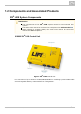
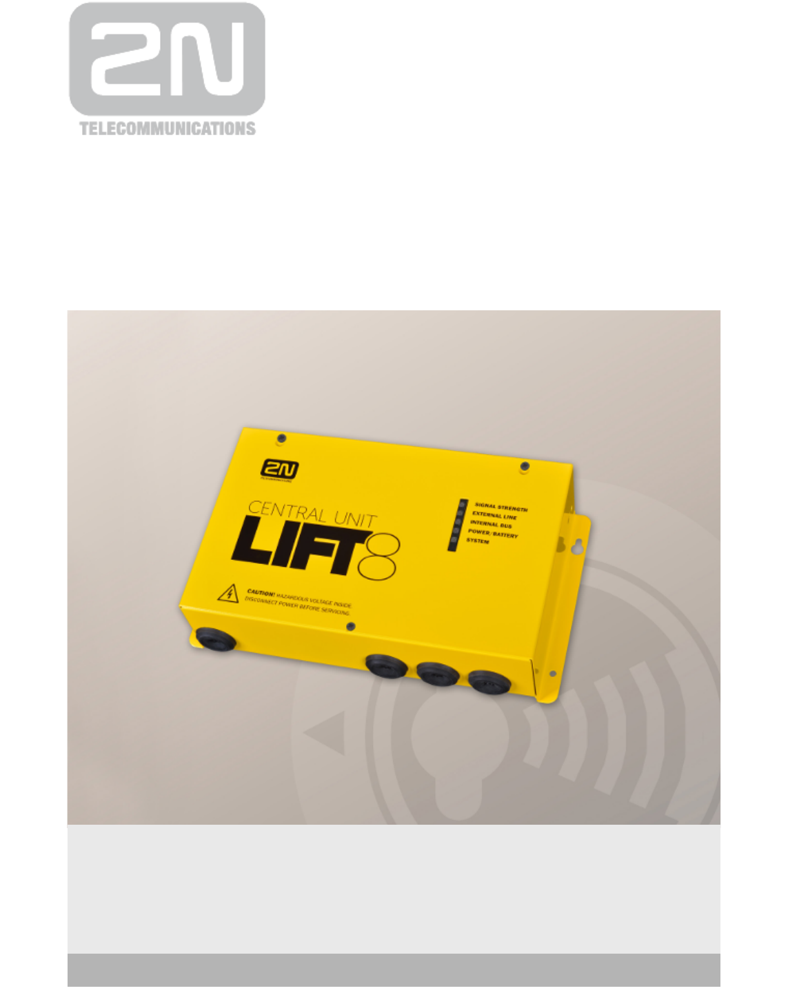
1.2 Components and Associated Products 2N® Lift8 System Components Notification The components of the 2N® Lift8 system cannot be used outside this system. The audio units cannot be connected to a telephone line without the CU! When shared by multiple shafts, the audio units cannot be connected without the CU and splitters. 918600 2N® Lift8 Central Unit Figure: 2N® Lift8 Central Unit For connection of up to 8 lifts to a GSM/UMTS/PSTN line. Including a power EURO cable and rechargeable battery.
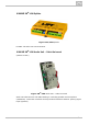
18620E 2N® Lift8 Splitter Figure: 2N® Lift8 Splitter For CU – lift audio unit interconnection. 918610E 2N® Lift8 Audio Unit – Cabin Universal (Normal version) Figure: 2N® Lift8 Audio Unit – Cabin Universal Audio unit electronics for lift cabin buiiding in. Including speaker and microphone (HandsFree). Connection terminals for all prescribed elements and door opening signal input (optional). 2N® TELEKOMUNIKACE a.s., www.2n.
918610EX 2N® Lift8 Audio Unit – Cabin Universal – Cable Version Contains LED, microphone and speaker connected to cables. Figure: 2N® Lift8 Audio Unit – Cabin Universal – Cable Version 918611E 2N® Lift8 Audio Unit – Machine Room/Control Centre Figure: 2N® Lift8 Audio Unit – Machine Room/Control Centre Audio unit for the machine room/control centre. Contains receiver (optional) and keypad for easy control. Makes it possible to communicate with other system audio units and configure the CU without a PC.
918612E 2N® Lift8 Audio Unit – Shaft Figure: 2N® Lift8 Audio Unit – Shaft Audio unit for cabin roof and shaft or cabin bottom. Robust yellow cover. HandsFree mode, ALARM button and Triphony, LED indicators. Not intended for use in the cabin. 918613E 2N® Lift8 Audio Unit – Compact Figure: 2N® Lift8 Audio Unit – Compact Robust, heavy-duty design. Standard-sized ALARM button including signage for the blind and backlit pictograms (hardened glass). Easy cabin wall mounting. Easy 2-wire connection.
918615ZK 2N® Lift8 Audio Unit – Fireman (1 button) 918615E 2N® Lift8 Audio Unit – Fireman (knob + 1 push-to-talk button) Figure: 2N® Lift8 Audio Unit – Fireman Used for fire fighting operations. Activates top priority calls. 918610FZK 2N® Lift8 Audio Unit – Fireman DPS (1 button) 918619E 2N® Lift8 Audio Unit – Fireman DPS (knob + 1 push-to-talk button) 2N® TELEKOMUNIKACE a.s., www.2n.
Figure: 2N® Lift8 Audio Unit – Fireman DPS Used by fire fighting operations. Activates top priority calls. 918620E 2N® Lift8 I/O Module Figure: 2N® Lift8 I/O Module Contains logical inputs and switch relays. 2N® TELEKOMUNIKACE a.s., www.2n.
918650E 2N® Lift8 GSM Module Figure: 2N® Lift8 GSM Module For central unit connection via a mobile network. Optional data connection for remote system configuration. 2N® TELEKOMUNIKACE a.s., www.2n.
918651E 2N® Lift8 UMTS Module Figure: 2N® Lift8 UMTS Module For central unit connection via a mobile network. Optional data connection for remote system configuration. 2N® TELEKOMUNIKACE a.s., www.2n.
918652E 2N® Lift8 PSTN Module Figure: 2N® Lift8 PSTN Module For central unit connection via an analogue line. 2N® TELEKOMUNIKACE a.s., www.2n.
918653E 2N® Lift8 VoIP Module Figure: 2N® Lift8 VoIP Module For central unit connection via a VoIP line. 2N® TELEKOMUNIKACE a.s., www.2n.
Cooperating 2N® Applications 918700E 2N® Lift8 Service Tool Figure: 2N® Lift8 Service Tool The 2N® Lift8 Service Tool application is intended for remote supervision and configuration of the 2N® Lift8 communicators. 918700E 2N® Lift8 Control Panel Figure: 2N® Lift8 Control Panel The 2N® Lift8 Control Panel application is intended for administration of users, lifts 2N® TELEKOMUNIKACE a.s., www.2n.
and authorisations. 918700E 2N® Lift8 Communicator Figure: 2N® Lift8 Communicator The 2N® Lift8 Communicator application is intended for receiving alarm calls by the dispatcher. 918700E 2N® Lift8 Server Figure: 2N® Lift8 Server 2N® TELEKOMUNIKACE a.s., www.2n.
The 2N® Lift8 Server application processes check calls and mediates communication between the CUs and PC applications. Associated 2N® Products 918655E – 2N® Lift8 External Pictograms Driver Figure: 2N® Lift8 External Pictograms Driver Transforms the 2N® Lift8 cabin LED outputs into universal pilot lamps. 2N® TELEKOMUNIKACE a.s., www.2n.
1.3 Upgrade The table below sums up the User Manual upgrade changes made so far. Manual version Description of changes Firmware 1.0.0 1.0.0 Basic version Firmware 1.5.0 1.5.0 1.6.0 VoIP parameters added Internal splitter four-lift configuration option (up to four cabin units can be connected to one internal splitter with lift 1-4 identification) Firmware 1.6.
1.4 Terms and Symbols Used Symbols Used The following symbols and pictograms are used in the manual: Safety Always abide by this information to prevent persons from injury. Warning Always abide by this information to prevent damage to the device. Caution Important information for system functionality. Tip Useful information for quick and efficient functionality. Note Routines or advice for efficient use of the device.
2. Description and Installation The section is divided according to system components into the following subsections: 2.1 PSTN/GSM/UMTS/VoIP Central Unit 2.2 Splitter 2.3 Audio Unit – Cabin Universal 2.4 Audio Unit – Machine Room 2.5 Audio Unit – Shaft 2.6 Audio Unit – Compact 2.7 PSTN Module 2.8 GSM/UMTS Module 2.9 VoIP Module 2.10 Audio Unit – Fireman 2.11 I/O Module Each subsection includes: Description of Components Before You Start Fitting Electrical Wiring 2N® TELEKOMUNIKACE a.s., www.2n.
2.1 PSTN/GSM/UMTS/VoIP Central Unit Description Figure: Central Unit 2N® TELEKOMUNIKACE a.s., www.2n.
Figure: Central Unit Indication Elements 2N® TELEKOMUNIKACE a.s., www.2n.
Figure: Central Unit Connectors There are a USB connector and reset button to the right of the CU (see the figure below). Figure: USB Connector and Reset Button 2N® TELEKOMUNIKACE a.s., www.2n.
Reset button function Reset equipment – press the button quickly. Restore factory values – press and hold the button until all the LEDs turn red. Then release the button and wait until the SYSTEM LED flashes yellow. Now press the button quickly to delete all the user settings. Zero backup rechargeable battery life counter – press and hold the button until all the LEDs turn red. Then release the button and wait until the POWER/BATTERY LED flashes yellow. Now press the button quickly.
Product Completeness Check Check whether the product package is complete before installation: 1 central unit 1 main bus terminal 4 bus connection terminals 4 wall plugs 4 wall plug screws 8 cable ties 1 battery connecting cables 1 brief manual 1 warranty sheet drilling template CU Mounting It is recommended to install the CU in a room that is secured against unauthorised persons, such as the lift machine room, switching station etc.
Power supply The CU is powered by 100–240V mains power. Warning Never connect an AC source or unstabilised DC source to avoid CU damage. Rechargeable Battery Connection and State Check Procedure: 1. Keep the CU disconnected from the mains. 2. Loosen the three screws on the upper cover of the CU. 3. Move the upper cover of the CU in such a way that you can remove it. 4. When removing the cover, proceed with caution, be careful about the earth wire connecting the cover with the CU bottom part.
Warning Adhere to the polarity of the rechargeable batteries! When the polarity of the batteries is reversed, there is a danger of fire or explosion or damage to the CU electronics. Rechargeable Batteries Caution If backup rechargeable batteries are used for the 2N® Lift8 power supply, the required backup of up to 1 h is guaranteed only if up to 20 audio units are connected in the system. The required 1h backup is not guaranteed if more than 20 audio units are installed.
Main bus 1 … Main bus power + 2 … Main bus power 3 … Main bus audio + 4 … Main bus audio 5 … Main bus data + 6 … Main bus data Caution 6-wire Use unshielded wires of the cross-section of 0.75 mm2. The maximum total cable length is 30 m with the cross-section of 0.75mm2. For higher lengths, enlarge the supply pair cross-section: PWR (60m – 1.5mm2 , or 100m – 2.5mm2).
Caution 2-wire Use unshielded wires of the cross-section of 0.75 mm2. The maximum total length per shaft is 600 m. With multi-strand cables, always use a pair of wires which match each other. With a tow cable, consider the cable length too. With special cables (to the cabin), use the neighbouring wires and make sure that the nearest surrounding wires do not radiate interference (power wire, video signal etc.). Tip Do not lead the bus close to power cables, especially in long-distance sections.
Examples of connection: 2N® TELEKOMUNIKACE a.s., www.2n.
CU Connection to Telephone Network You can connect the CU to any of the following telephone networks: PSTN PBX GSM UMTS VoIP PSTN 2N® Lift8 works in a broad band regardless of polarity and line parameters (refer to Technical Parameters). Connect it using the enclosed cable with an RJ–12 terminal. It is the most reliable and simplest connection. The disadvantage is the operating cost (fixed fee).
Telephone line requirements The line must not be a dual or party one. The telephone socket and its wiring are usually the network provider's property and may not be tampered with. Other recommendations Notify the telephone network provider of your 2N® Lift8 installation and submit certification upon request. Your follow-up wiring must comply with the relevant safety regulations. You are recommended to secure your cabling against pirate connection (with a telephone lock, e.g.).
Recommendation In places with a poor signal quality find an appropriate place or use a special (directional) antenna. Protect the SIM card from theft. If a prepaid SIM card is used, make sure that the credit is monitored and topped up in time. UMTS This is used in particular where no PSTN line is available. If 2N® Lift8 is connected via UMTS, the system can be configured remotely using the 2N® Lift8 Service Tool appli cation.
2.2 Splitter Description The splitter helps extend installations by interconnecting audio units in multiple lift shafts (audio units can be connected directly to the CU in one-shaft installations). It is connected with the CU via six wires (power, audio, data). Audio units are connected to the splitter using a two-wire bus. The splitter also contains a make/break contact for the lift blocking function. There can be up to 7 splitters (according to the count of lift shafts).
Electrical Installation Main Bus Connection Remove the push-in terminal board from the main bus connector and connect six wires from the CU maintaining the polarity (power + -, audio + -, data + -). See the printed figure on the splitter cover. Main bus 1 … Main bus power + 2 … Main bus power 3 … Main bus audio + 4 … Main bus audio 5 … Main bus data + 6 … Main bus data Warning Maintain the connection polarity to avoid a 2N® Lift8 error.
Address Configuration Configure the splitter address for the given lift using a 10-position switch 0–9 (see the figure). Configure lift 2–8 as 2–8 (set the switch to position 5 for lift 5, e.g.). Audio Unit Connection Connect up to 5 audio units to each splitter. As the splitter has only 3 audio unit termin als, connect 1–2 audio unit in parallel. Remove the slide-on terminals from the audio unit connectors and connect the twin-wire. Adhere to polarity to avoid the audio unit er ror.
Termination Resistance Caution Find the 3-pin termination resistance connecting jumper between the main bus connector and lift number switch. Connect the jumper to the first and last device (CU, splitter or I/O module) on the bus. Refer to the CU describing section for more details on termination resistance mounting. By default, the termination resistance jumper is off. Figure: Termination Resistance Off 2N® TELEKOMUNIKACE a.s., www.2n.
Mounting Types See below for the mounting types and necessary components. Install the device on sites not exposed to water leakage or condensation. Wall Mounting Use appropriate wall plugs and screws for mounting (not included in the delivery). Hang the device using the pre-drilled holes on the device bottom. Figure: Wall Mounting DIN Rail Mounting Mount the device on a standard TS 35 DIN rail. The recommended DIN rail length is 14 cm. Figure: DIN Rail Mounting 2N® TELEKOMUNIKACE a.s., www.2n.
Caution The warranty does not cover any defects or failures of the product arisen as a result of improper mounting in contradiction to these instructions. A wrong mounting procedure may lead to damage to the electronics due to water infiltration. The splitter circuits are constantly under voltage and water leakage causes electrochemical reaction. No warranty can be claimed for products damaged in this manner! 2N® TELEKOMUNIKACE a.s., www.2n.
2.3 Audio Unit – Cabin Universal Description The user does not come into a direct contact with this product. The control and indication elements depend on the specific installation. The functions of the indication elements correspond to the applicable standards Figure: Audio Unit – Cabin Universal Before You Start Installation Conditions The panel has to be installation-ready, including speaker perforation.
Product Completeness Check Check the product for completeness before installation. The cabin audio unit package contains (assembled): 1 4 1 1 1 1 1 5 electronics board terminals slid onto the board; see the photo jumper slid onto the board; see the cover printing mounting panel speaker connected directly or by cable microphone connected directly or by cable cover with printing tightening straps Mounting Electronics Mounting This audio unit is intended for mounting behind the lift control panel.
the audio unit on a perfectly degreased surface with a high-quality double-sided foam self-adhesive tape. Safety Leave no gap between the lift control panel and the audio unit surface to avoid acoustic speaker fault and acoustic speaker-microphone feedback. Do not use this type of audio unit in a position other than mounted on a sufficiently large board. The acoustic properties of an uninstalled audio unit cannot be guaranteed.
Electrical Installation Description of Terminals, Connectors and Jumpers Figure: Terminals, Connectors and Jumpers on Audio Unit – Cabin Universal 1 Terminals Audio unit bus 7 Connectors “Connection made” LED 2 ALARM, voltage activation 8 “Request received” LED 3 ALARM, contact activation 9 Microphone connector (optionally) 4 CANCEL, voltage activation 10 Induction loop connector 5 CANCEL, contact activation 11 Speaker connector 6 Alarm 2 (set 2) 13 Servicing connector 12 Configur
Audio Unit Location Configuration The audio unit is configured as a cabin audio unit by default and so it is not necessary to change the configuration. To use the audio unit in a room other than the lift cabin, proceed as follows. Procedure 1. Reconfigure the jumper on configuration jumper 12. 2. If there is poor access to the pins, you can remove the electronics cover. Slightly loosen the four screws and shift the cover downwards. Now you can remove the cover. 3.
Figure: Address Configuration for Audio Unit – Cabin Universal Note Make sure that two audio units do not have an identical address to avoid system error. The position-setting jumpers are employed exceptionally, e.g. where a certain audio unit type is used in a position other than normally intended. To recover the initial address setting, follow the drawing on the cover. 2N® TELEKOMUNIKACE a.s., www.2n.
Bus Connection Pull the terminal out of connector 1 - Audio units bus, connect the bus audio units wires and replace the terminal to connector 1. Mind the polarity. Warning Connection to different, e.g. higher-voltage, cables leads to damage or destruction of the audio unit. Maintain polarity while connecting the audio unit to avoid audio unit error. Caution The audio unit is powered via a 2-wire bus. Disconnection of these wires results in the audio unit switch-off. Avoid the audio unit address duplicity.
Voltage control Requirements DC 12 to 48V voltage The voltage signal must be active even during a power failure. Procedure 1. Move the ALARM terminal two pins up into position (2). 2. For activation by voltage connection, leave the jumper as it is (5th pin on jumper 12) – ALARM without jumper fitted (factory setting). 3. For activation by voltage disconnection, fit the jumper (5th pin on jumper 12) – ALARM inverted – jumper fitted. Warning Ignoring the instructions above may lead to product damage.
Voltage control Requirements DC 12 to 48V voltage Procedure 1. Move the CANCEL terminal two pins up into position (4). 2. For activation by voltage connection, leave the jumper as it is (6th pin on jumper 12) – CANCEL without jumper fitted (factory setting). 3. For activation by voltage disconnection, fit the jumper (6th pin on jumper 12) – CANCEL inverted – jumper fitted. Warning Ignoring the instructions above may lead to product damage.
Note The cables required for this configuration are not part of the standard delivery but are available upon agreement. In this configuration, the auxiliary indicators on the PCB are not illuminated. External Pictogram Driver Description The device transforms the 2N® Lift8 Car Unit LED outputs into a universal pilot lamp, whose outputs are capable of driving two lamps rated at the maximum of 36 Volts, 0.5 Amps. The outputs are galvanically isolated from the Car Unit.
Caution External pictograms are connected to connectors 7 and 8 on the cabin audio unit. The manufacturer, 2N TELEKOMUNIKACE a.s., hereby declares that the 2N® Lift8 External Pictogram Driver is in compliance with the essential requirements and other relevant provisions of the 1999/5/EC Directive. The Declaration of Conformity is attached to the basic module of 2N® Lift8 and also available at www.2n.cz. Volume Configuration Slightly loosen the four screws and shift the cover downwards.
Rescue Process The rescue (extrication) process is activated after the alarm call end. The yellow LED keeps shining on the audio unit. The service technician enters a valid password via the 2N® Lift8 voice menu to terminate the process. When the rescue password is entered via the voice menu, the yellow LED goes off on the audio unit and the 'Rescue process was terminated' is played. Caution Access the voice menu (during an incoming call to L8 or from the machine room) to terminate the rescue process.
2.4 Audio Unit – Machine Room Description The machine room audio unit is intended for installation in the machine room or as an intercom solution located in the reception. It has some distinctive compared with the other types: The audio unit is equipped with a keypad. The keypad helps you select various functions and program the system. You can connect a handset to the audio unit for better acoustic properties in noisy environments.
Operation 1. This type of audio unit is operated by qualified people (lift maintenance staff, e.g.). 2. Push the TRIPHONY button to activate voice communication with the other audio units of the same lift. Push and hold the button for over 2 seconds to activate communication with another lift (to display a voice menu and select the required lift number). 3. Push the ALARM button to call the control centre, for example. The audio unit calls the numbers configured in the ALARM memory – set 2 (021–026).
Electrical Installation Description of Connectors There are 3 connectors to the right under the cover: Figure: Machine Room Audio Unit Connectors Address Configuration There is a group of jumpers under the transparent front cover. Do not use any of them if the machine room is only intended for the given lift. The audio unit identifies itself as the machine room for the given lift.
Bus Connection Loosen the screws to the right and open the connector cover. There is just one connector under the cover: a bus connector. Pull out the terminal from the connector, connect the wires and replace the terminal. Make sure that the polarity is maintained. Warning Connection to different, e.g. higher-voltage, cables leads to damage or destruction of the audio unit. Maintain polarity while connecting the audio unit to avoid audio unit error. Caution The audio unit is powered via a 2-wire bus.
Caution Use the trimmer to set the best acoustic properties eliminating feedback. Volume configuration only works in the HandsFree mode. 2N® TELEKOMUNIKACE a.s., www.2n.
2.5 Audio Unit – Shaft Description This audio unit is designed for installation on the lift shaft bottom or lift cabin roof, or wherever it is necessary to communicate (during lift maintenance, e.g.). The audio unit is enclosed in a robust yellow cover. It is not intended for outdoor use but perfectly tolerates the conditions in lift shafts: is resistant against fall of small objects, dripping oil, etc.
Operation 1. This type of audio unit is operated by qualified people (lift maintenance staff, e.g.). 2. Push the TRIPHONY button to activate voice communication with the other audio units of the same lift. 3. Push the ALARM button, for example, when someone falls down the shaft. 4. The audio unit calls the numbers configured in the ALARM memory – set 2 (021–026). 5. The ALARM button illumination (not required by default) helps you find and activate the audio unit easily in the dark.
Electrical Installation Connectors The audio unit has one connector for bus connection. The second RJ–11 connector is used for handset connection. Both the connectors are under the side doors. Audio Unit Location Configuration Audio unit location means configuration of jumpers (see the cover print). You do not have to change the jumper configuration if you are installing the audio unit at the shaft bottom. Otherwise, proceed as follows: Procedure 1.
Caution The audio unit is powered via a 2-wire bus. Disconnection of these wires results in the audio unit switch-off. Handset Connection Use the handset supplied with the audio unit and the included cable with telephone terminals. Caution If the handset is not connected, the audio unit works in the HandsFree mode. A handset other than that supplied by the manufacturer may not work. Volume Configuration Open the protective door on the audio unit and adjust the volume using the trimmer.
2.6 Audio Unit – Compact Description Robust, heavy-duty design. Standard-sized ALARM button including signage for the blind and backlit pictograms (hardened glass). Designed for cabin wall mounting. No drilling is required as the device is to be wall-mounted. Figure: Description of Audio Unit – Cabin Compact Operation Push the ALARM button to activate the audio unit. The 'Establishing connection' symbol goes on. The 'Connection established' symbol goes on when communication is set up.
Before You Start Requirements Make sure that the lift wall is even. Make sure that the installation meets the standard requirements (ALARM button height and distance from the other lift buttons, e.g.). Product Completeness Check Check the product for completeness before installation.
Figure: Mounting Hole Dimensions for Audio Unit – Cabin Compact Note: Two 2.5 mm holes in the symbol window are intended for installations without access to the back side of the installation panel. The 2.5 diameter is suitable for plywood wall mounting (chipboard, laminated plastic, etc.) with the screws included in the delivery. Drill M4-threaded holes for metal panel mounting from the front side. Do not complete the mounting procedure until connecting the device electrically (see below).
Description of Terminals Terminals AUDIO UNIT BUS ALARM ter minals Voltage = voltage control (on/off) Contact = contact control (on/off) Voltage = voltage control (on/off) CANCEL ter minals Contact = contact control (on/off) ALARM 2 terminal Contact = contact control (closing) Description Audio unit bus (2-wire) connection, polarity must be maintained.
Connectors Figure: Connectors on Audio Unit – Cabin Compact (New Type) Safety Make sure that the minimum button isolation distance is 1.5 mm and breakdown voltage is 1,500 V. The button contacts may not be connected to any other circuits. If you cannot meet these conditions, use voltage control. You can use the switch on the audio unit front side or closing/opening button connected to the ALARM CONTACT connector or both of them if necessary.
Procedure 1. Insert the hexagonal spanner (included) in the hole on the product bottom edge (window lock screw) and turn left (about 10 times) until you feel resistance. 2. The window slides down by itself or with a slight aid, revealing its upper brim. Rotary switch position Figure Position 1 – ALARM normal, CANCEL normal, cabin Position 2 – ALARM inverted, CANCEL normal, cabin Position 3 – ALARM normal, CANCEL inverted, cabin Position 4 – ALARM 4. Set the required address.
Contact closing/voltage connection control of ALARM, contact opening/voltage disconnection control of CANCEL Set the rotary switch (under the front glass) to position 3 to make ALARM be controlled by contact closing or voltage connection and CANCEL be controlled by contact opening or voltage disconnection.
Volume Setting 1. Insert the hexagon key wrench (included in the delivery) in the hole on the product bottom edge (window lock screw) and turn left (about 10 times) until you feel resistance. 2. The window slides down by itself or with a slight aid, revealing its upper brim. 3. Tilt the window forward and remove it. 4. Set the required volume level using a trimmer. 5. Replace the window. 6.
Figure: Mounting of Audio Unit – Cabin Compact a. If the cabin wall is thin (stainless steel sheet), use the four M4 screws of the length of 8 mm and fan washers included in the delivery. b. If the cabin wall is thick (up to 20 mm – laminated chipboard, e.g.), use the four M4 headless screws of the length of 30 mm. Screw the screws into the audio unit backside holes with the enclosed spanner and tighten them. Then push the set through the pre-drilled holes and insert the fan washers and nuts from the back.
c. the next page. TIP: If you have drilled the corner holes too, use the four M4 headless screws of the length of 30 mm included in the delivery. Screw the screws into the audio unit backside holes and tighten them as instructed in item b) above. Although not equipped with nuts, the screws will prevent the product from shifting or turning. Mounting Completion – Without Rear Access 1. 2N® TELEKOMUNIKACE a.s., www.2n.
1. Insert the hexagon key wrench (included in the delivery) in the hole on the product bottom edge and turn left (about 10 times) until you feel resistance. 2. The window slides down by itself or with a slight aid, revealing its upper brim. 3. Tilt the window forward and remove it. 4. Now you have access to the two corner holes. Put the audio unit (including the wires) on the cabin wall with the pre-drilled holes.
2.7 PSTN Module Description of Connection The module should be part of the Central Unit (hereinafter referred to as CU). If the CU does not contain the PSTN module, proceed as follows: 1. Keep the CU disconnected from the mains. 2. Loosen the three screws on the upper cover of the CU. 3. Move the upper cover of the CU in such a way that you can remove it. 4. When removing the cover, proceed with caution, be careful about the earth wire connecting the cover with the CU bottom part.
8. Now connect the PSTN line. There are 2 options: using the RJ 11 connector; using a slide-on terminal board. Warning While fitting the module, make sure that all the pins are fitted correctly into the connector to avoid module damage. 2N® TELEKOMUNIKACE a.s., www.2n.
2.8 GSM/UMTS Module Description of Connection The module should be part of the Central Unit (hereinafter referred to as CU). If the CU does not contain the PSTN module, proceed as follows: 1. Keep the CU disconnected from the mains. 2. Loosen the three screws on the upper cover of the CU. 3. Move the upper cover of the CU in such a way that you can remove it. 4. When removing the cover, proceed with caution, be careful about the earth wire connecting the cover with the CU bottom part.
9. Now insert the SIM card and connect the antenna. Warning While fitting the module, make sure that all the pins are fitted correctly into the connector to avoid module damage. Caution In places with a poor signal quality find an appropriate place or use a special (directional) antenna. Should you have DTMF transmission problems, set parameter 710 to 1 (for GSM modules only). 2N® TELEKOMUNIKACE a.s., www.2n.
2.9 VoIP Module Description of Connection The module should be part of the Central Unit (hereinafter referred to as CU). If the CU does not contain the PSTN module, proceed as follows: 1. Keep the CU disconnected from the mains. 2. Loosen the three screws on the upper cover of the CU. 3. Move the upper cover of the CU in such a way that you can remove it. 4. When removing the cover, proceed with caution, be careful about the earth wire connecting the cover with the CU bottom part.
8. Now connect the VoIP line via the RJ–45 connector. Warning While fitting the module, make sure that all the pins are fitted correctly into the connector to avoid module damage. 2N® TELEKOMUNIKACE a.s., www.2n.
2.10 Audio Unit – Fireman The Fireman audio unit is available in two versions. 2.10.1 Fireman PCB 2.10.2 Fireman 2.10.3 Fireman – Mechanical Mounting 2N® TELEKOMUNIKACE a.s., www.2n.
2.10.1 Fireman PCB Description: 1-Button Version The Fireman audio unit improves the fire fighting operations by setting up top priority calls to the cabin audio unit in one and the same lift shaft. If any of the machine room audio units is configured as the control centre (intercom), you can join in the Fireman call. Install the Fireman audio unit in a dedicated space that can be easily accessed by firemen.
Description: Knob+Button Version (Push-To-Talk) The Fireman audio unit improves the fire fighting operations by setting up top priority calls between the Fireman audio unit and the cabin and machine room audio units in one and the same lift shaft. If any of the machine room audio units is configured as the control centre (intercom), you can join in the Fireman call. Install the Fireman audio unit in a dedicated space that can be easily accessed by firemen.
Caution The Fireman calls has the highest priority and suspends all the other calls except for the Fireman call set up in another shaft. The Fireman call is set up to the cabin and machine audio units in one and the same shaft. You can join in the Fireman call from a machine room audio unit configured as the intercom. Button is not included. Before You Start Installation Conditions Make sure that the panel is ready for installation, check the speaker perforation area.
Figure: Cabin Audio Unit – Universal Mounting Hole Dimensions To mount the unit, you need 4 electrically spot-welded (from the inner panel side) M3 or M4 screws, a sufficiently perforated speaker area and a microphone hole. If needed, a high-quality double-sided foam self-adhesive tape can be used for installation on a perfectly degreased surface. Warning Leave no gap between the lift control panel and the audio unit surface to avoid acoustic speaker fault and acoustic speaker-microphone feedback.
Separate Microphone Mounting If the microphone is supplied separately on a 25×25 mm large board with self-adhesive foil and with a cable, you can mount it easily behind any hole in the panel (keep the minimum hole diameter of 5 mm or a group of smaller holes of the same total area). Just glue the microphone directly onto the required place from behind (be sure to degrease and clean the surface carefully before mounting!).
Electric Installation Description of Terminals, Connectors and Jumpers Figure: Terminals, Connectors and Jumpers on Cabin Audio Unit – Universal Board 2N® TELEKOMUNIKACE a.s., www.2n.
1 Terminals Audio unit bus 7 Connectors Unconnected 2 Unconnected 8 LED 9 Microphone connector (optional) 10 Induction loop connector 11 Speaker connector 13 Servicing connector Unconnected (1-button version) 3 4 Fireman call activation – with detent (2-button version) Unconnected Activation/Deactivation – without detent (1-button version) 5 Push to talk – without detent (2-button version) 6 Unconnected Configuration Jumpers 12 The lower pin defines the button count jumper connected – 1
Volume Setting Loosen the four screws slightly and move the cover downwards. Remove the cover. Use the trimmer in the lower part of the electronics to adjust the volume (see the figure below). Caution Use the trimmer to set the best acoustic properties while eliminating feedback. 2N® TELEKOMUNIKACE a.s., www.2n.
2.10.2 Fireman Description: 1-Button Version The Fireman audio unit improves the fire fighting operations by setting up top priority calls to the cabin audio unit in one and the same lift shaft. If any of the machine room audio units is configured as the control centre (intercom), you can join in the Fireman call. Install the Fireman audio unit in a dedicated space that can be easily accessed by firemen.
(for longer than 2 s) on the audio unit keypad (green LED flashing) to leave the call without terminating it. Caution The Fireman calls has the highest priority and suspends all the other calls except for the Fireman call set up in another shaft. The Fireman call is set up by the cabin audio unit in one and the same shaft. You can join in the Fireman call from a machine room audio unit configured as the intercom.
Install the Fireman audio unit in a dedicated space that can be easily accessed by firemen. The Fireman call has the highest priority, suspending all the other calls (refer to Function Description). Turn the knob (0 > 1) to activate the Fireman call. The call duration is infinite. Return the knob to stop the call. The Fireman call setup is signalled by the Fireman audio unit LED (blue LED shining around the button).
longer than 2 s) on the audio unit keypad (green LED shining) to join in the call. Push (for longer than 2 s) on the audio unit keypad (green LED flashing) to leave the call without terminating it. Caution The Fireman calls has the highest priority and suspends all the other calls except for the Fireman call set up in another shaft. The Fireman call is set up to the cabin and machine audio units in one and the same shaft.
Description of Terminals, Connectors and Jumpers Figure: Terminals, Connectors and Jumpers on Fireman Audio Unit Board Terminals and Connectors 5 2 microphone connectors 1 Speaker connector 2 Audio unit bus 6 Detent button (knob) connector 3 Volume setting (trimmer) 7 Configuration jumper 4 Button connector (Push to talk) 8 Servicing connector Bus Connection Remove the audio unit cover and unplug terminal 2 (audio unit bus). Connect the bus and replace the terminal keeping polarity.
Caution The audio unit is powered via a 2-wire bus. Unplugging these wires results in the audio unit switch-off. Volume Setting Use the trimmer on the electronics board to adjust the volume (refer to the Description of Terminals, Connectors and Jumpers above). Caution Use the trimmer to set the best acoustic properties while eliminating feedback. Mounting Completion Having connected all the wires, check the bushings if employed for tightness. 2. Install the front panel carefully.
2.10.3 Fireman – Mechanical Mounting Mechanical Mounting – Mounting Types See below for an overview of mounting types and list of necessary components. Wall Mounting For concrete and steel structures, etc. What you need for installation: 2N ® Lift8 Fireman only (no need for covering frame) Flush Mounting – Classic Bricks What you need for installation: Properly cut-out hole or, optionally, a flush mounting kit, Part No.
Flush Mounting – Thermally Insulated Wall What you need for installation: Longer screws (depending on the thermal insulation thickness) For 2N® Lift8 Fireman: Covering frame: contact your distributor Flush Mounting – Hollow Bricks What you need for installation: Flush mounting kit, Part No. 9151001 For 2N® Lift8 Fireman: Covering frame: contact distributor your Flush Mounting – Plasterboard What you need for installation: Flush mounting kit for plasterboard, Part No.
Common Mounting Principles Tip Choose flush mounting where possible to make your product more elegant, vandal-resistant and safer. You can buy the flush mounting kit in advance and commission a specialised firm to install the device. Moreover, the flush mounting kit helps you level the audio unit properly (with a maximum vertical position deviation of 2°). Caution Check the diameter of the plug holes. If the holes are too large, the plugs may come loose! Use a building glue for fixing if necessary.
1. Choose the audio unit position according to the supply cables too. If the cables lead inside a structure or wall, use the holes on the audio unit bottom. 2. Drill plug holes of the depth of 70 mm (as shown in the figure below) into concrete and similar walls. Push or hammer the supplied plugs into the holes. If the plugs are too loose, use a mounting glue. Use fitting elements of your own for steel structures – metric screws and nuts, for example. 3. Remove the front panel from the audio unit. 4.
1. Drill a hole using the template included for all the necessary cables. Be careful while drilling as this type of mounting does not allow to balance rather great deviations later! 2. Unpack the frame, put the audio unit onto it and put this set on the hole to test whether the hole is deep enough and its uneven edge is completely covered by the frame. 3. Push or hammer the supplied plugs into the holes. If the plugs are too loose, use a mounting glue. 4. Remove the front panel from the audio unit. 5.
Flush Mounting – Hollow Bricks It is practically impossible to fit plugs into hollow bricks because the inner brick walls are too thin for drilling. Therefore, use the flush mounting kit and follow the instructions included therein. 2N® TELEKOMUNIKACE a.s., www.2n.
Flush Mounting – Plasterboard Use the flush mounting kit for plasterboard walls and follow the instructions included therein. 2N® TELEKOMUNIKACE a.s., www.2n.
2.11 I/O Module Description The purpose of the I/O Module is to interconnect the Central Unit (CU) with the lift signalling. It is designed for usage of binary inputs or switching of relay inputs. It is connected to the CU via 6 wires (power, audio, data). The inputs/outputs are connected to the I/O Module via 2-pin slide-on terminals.
Figure: I/O Module – Upper Side Electrical Installation Caution Local power is not supported. Do not connect any local power supply. The main bus power is sufficient for the I/O Module. Main Bus Connection Take the 6-pin main bus connector from the package and connect 6 wires from the CU maintaining polarity (power + -, audio + -, data + - ) – see the I/O Module cover. Connect the devices serially (in line). Parallel connection is not allowed. Refer to the CU section for more details.
Main bus 1 2 3 4 5 6 … … … … … … Main Main Main Main Main Main bus bus bus bus bus bus power + power audio + audio data + data - Warning Maintain the connection polarity to make the 2N® Lift8 system work correctly. Warning The bus is electrically isolated from the telephone line circuits according to the EN60950 requirements and its low voltage cannot cause any electrical accident.
LED Indicators The I/O Module is equipped with ten LED indicators: two I/O Module status signalling LEDs, four input status signalling LEDs and four output status signalling LEDs. Refer to the table for details. Name Colour OK Green ERR Red Logic input Description If everything is OK, the power supply and bus are connected, the I/O Module is communicating with the CU, the LED is flashing.
Output Relay Connection Every I/O Module is equipped with 4 bistable relays with the maximum load of 250 V / 5 A per contact. Never exceed this limit to avoid system damage. When the relay is closed, the respective LED signals this state. You can configure the relay function in the 2N® Service Tool application.
Figure: Wall Mounting DIN Rail Mounting Mount the device on a standard TS 35 DIN rail. The recommended DIN rail length is 14 cm. Figure: DIN Rail Mounting Caution The warranty does not cover any defects or failures of the product arisen as a result of improper mounting in contradiction to these instructions. A wrong mounting procedure may lead to damage to the electronics due to water infiltration. The splitter circuits are constantly under voltage and water leakage causes electrochemical reaction.
3. System Configuration The system is supplied pre-configured. This section describes the 2N® Lift8 configuration. There are three ways how to progr am 2N® Lift8. 3.1 2N® Lift8 Programming 3.2 Table of Parameters (FW 1.6.0) 2N® TELEKOMUNIKACE a.s., www.2n.
3.1 2N® Lift8 Programming The advantage of the 2N® Lift8 (hereinafter referred to as programmed via the CU where all the parameters are stored. to reconfigure anything to replace an Audio Unit and you can multiple lift systems, for example. The memory is independent L8) system is that it is Hence, you do not have program just one CU in of the CU power. Before You Start Fill in all the values to be changed in the prepared form with a clear table of basic functions.
Programming Procedure Having entered the programming mode, you can change any programmable value(s) in any order. Proceed as follows: enter the function number and then the value. Use an asterisk as a separator or Enter. In general, the function has the following format: function number value The function number has three digits (see the table). After you enter the function number and an asterisk, L8 reports the number or name, current value and potential range of the parameter to be programmed.
Troubleshooting L8 fails to respond correctly to DTMF commands, e.g. the programming mode cannot be entered. Today, voice transmission is prevailingly digital, using variable compression algorithms. Therefore, the DTMF signal to be transmitted is often distorted. Moreover, it may, in some cases, be transmitted through the so-called command channel, whose delay may differ from that of the speech channel.
2N® TELEKOMUNIKACE a.s., www.2n.
3.2 Table of Parameters (FW 1.6.
1 = with confirmation DTMF (1), 2 = confirmation of picking up (supported only for GSM/UMTS/VoIP), 3 = CPC Antenna, 4= CPC KONE, 5 = P100, 6 = autodetection DTMF protocol (CPC Antenna/P100), 7 = CPC Antenna 2N ext, 8 = CPC KONE 2N ext, 9 = P100 2N ext 111–116 Set 1 – confirmation mode for number 1–6 1–6 1 2N ext is a protocol that transmits the shaft number and audio unit position together with the ID (to be displayed in 2N® Lift8).
026 Set 2 – ALARM 2 button memory 6 027 Insert specific character in ALARM memory set 2 028 Set 2 - count of automatic dialling cycles for ALARM 2 ories is completely empty, use set 1. up to 16 digits: 0–9 If 0 is configured, only the first number in the memory is called regardless of the count of saved numbers.
077 Insert a character in checking call memory 078 Count of automatic dialling cycles for checking call 171–176 081 082 083 084 085 086 Confirmation mode for number 1–6 Error call memory 1 Error call memory 2 Error call memory 3 Error call memory 4 Error call memory 5 Error call memory 6 2N® TELEKOMUNIKACE a.s., www.2n.
087 Insert specific character in fault reporting memory 088 Count of automatic dialling cycles for error call 181–186 501 502 503 504 505 506 Confirmation mode for number 1–6 Default output state of IO module 1 Default output state of IO module 2 Default output state of IO module 3 Default output state of IO module 4 Default output state of IO module 5 Default output state of IO module 6 0–9 3 1 = with confirmation DTMF (1), 2= confirmation of picking up (supported only for GSM/UMTS/VoIP), 3
507 508 Default output state of IO module 7 Default output state of IO module 8 600 Battery capacity 700 SIM PIN ABCD empty ABCD empty 1–740 13 and 4 will be on after the system start. In 100mAh units (x*100mAh "13=1,3Ah, 740=74Ah") up to 16 0000 digits: 0–9 710 DTMF transfer enhanced mode enabled 0 = disabled, 1 = enabled 0–1 0 Dial-in is used for calling via the PSTN module. When a call is answered, the dial-in is sent and only then the dialling or constant tone is awaited.
914 Delayed call 0–1000 s 0s Used only with connected CANCEL input on the cabin audio unit. 915 Max. TRIPHONY time 10–9999 s 7200 s Maximum TRIPHONY period after which TRIPHONY is terminated automatically. 917 Hang-up time 500–9999 ms between calls 5000 ms For PSTN lines only. 918 Max. telephone line test time 1–20s 5s not implemented 940 Min. dialtone period 200–2000 ms 400 ms The tone must be longer than a half-period of the busy tone! 941 Min.
968 Machine room alerting 1–60 s time (siren) 1s not implemented 969 Intercom alerting time 1s not implemented 1–60 s 0 = user recorded, 1 = voice menu language 973 Language for numeric messages 0–1 974 Intercom identification number up to 16 digits: 0–9 Local (cabin) message sequence 975 976 977 978 (before confirmation by 1) Checking call message sequence Call confirmation message sequence empty User-recorded digits are played only if values 11, 12 or 13 are set in parameters 975–97
981 Checking call mode 982 Checking call interval 983 Checking call period 0 = disabled 1 = enabled, the first call in 3 minutes and then as set in parameter 983 2 = enabled, the first call in 2 hours and then as set in parameter 983 3 = enabled, as set in parameter 983 4 = enabled, the call on the nearest day set in parameter 986 5 =enabled, the first call in 3 minutes and then as set in parameter 983 0–5 0 hhmmhhmm Set announcements into lower traffic (lower tariff) 00002359 time, generated at r
800 Set time hhmm Read the current time setting and configure a new one if necessary. * 801 Set date RRMMDD Read the current date setting and configure a new one if necessary. * 898 Cancel working configuration Cancel all the changes performed during this configuration call except for the date/time setting – confirm this by an asterisk.
1105 SIP server 1106 User 1107 Password 1108 Enable in-band DTMF detector 1109 SIP server port 1220 1221 Camera type Resolution Compression ratio Client enabled Server IP addres Server port Password 1222 1230 1231 1232 1234 Set the IP address for connection to the counterparty (PBX, operator). ** Set the user name for connection to the counterparty (PBX, operator). ** Set the password for connection to the counterparty (PBX, operator).
How to Record Announcement From PC Apply the 2N® Service Tool to record user announcements and numerals to 2N® Lift8. Refer to Subs. 5.3, 2N® Service Tool – Use, for details. 2N® TELEKOMUNIKACE a.s., www.2n.
4. Function and Use In this section there is a description of the basic and expanded functions of the product. Here is what you can find in this section: 4.1 4.2 4.3 4.4 4.5 4.6 4.7 User Instructions Control Centre Instructions Function Description (for Advanced Users) Call Confirmation Types Lift Blocking Function Four-Lift Version Intercom Function 2N® TELEKOMUNIKACE a.s., www.2n.
4.1 User Instructions Cabin The cabin audio unit is intended for an untrained user. Nevertheless, the instructions can be placed in the lift cabin, e.g., to help the people trapped in the lift communicate with the control centre. Meaning of pictograms (icons) The yellow Wait icon is illuminated while connection with the control centre is being set up. The green icon lights up when connection has been set up and confirmed by the control centre. The green icon lights up whenever TRIPHONY is in progress.
Press 0 to dial the public telephone network Select the lift X number to dial the lift Press 1 to dial the lift cabin Press 2 to dial the cabin roof Press 3 to dial the lift cabin bottom Press 4 to dial the shaft bottom Press 5 to dial the machine room Press # to return to the main menu Press 9 for administration Press 1 to enter the programming menu Press 2 to terminate the rescue process Press 3 to listen to your communicator info 1.
4.2 Control Centre Instructions ALARM Call 1. Press the ALARM button on any audio unit to make L8 call the control centre (refer to Automatic Dialling for details). 2. A received call is either confirmed as configured (parameters 111–116 > Confirmation mode for memory 1–6 ALARM call – set 1). By default, confirmation of DTMF 1 is set in L8. 3. If the control centre is equipped with the 2N® Communicator application, you can configure automatic sending of DTMF 1 after call pick-up. 4.
Calling to lift which was the last to call Alarm Having entered the voice menu, press 0 to call the lift was the last to dial the Alarm function. This function operates only if you are calling to L8 via a PSTN, GSM, UMTS or VoIP network. Note The 9 selection serves primarily for the L8 configuration – refer to the Configuration section.
4.3 Function Description (for Advanced Users) Purpose of Section The purpose of this section is to help technicians solve problems if any. If the system fails to work properly and a well-trained technician, who monitors its operation step by step according to the description included herein, gets to a point where the description and reality are in contradiction, he or she describes the contradiction, thus facilitating troubleshooting.
Machine Room Voice Menu Press 0 to dial the public telephone network Press the lift number X to dial the lift Press 1 to dial the lift cabin Press 2 to dial the cabin roof Press 3 to dial the lift bottom Press 4 to dial the shaft bottom Press 5 to dial the machine room Press # to return to the main menu Press 9 for administration Press 2 to enter the programming menu Press 2 to terminate the rescue process Press 3 to listen to your communicator info Press # to return to the main menu Press # to end the call
Incoming Call The control centre can also call back to the communicator. The CU automatically receives every incoming call, identifies itself and, via a voice menu (DISA), offers you another function to get through to the required audio unit. Incoming calls are time limited as outgoing calls and are processed in the same way (extension, termination). Press 0 in the voice menu for connection with the last-calling audio unit.
Explanations: na = not applicable ns = not served (ns* for machine room configured as the control centre: the Fireman call is entered whenever the phone is answered) q = put in queue S = suspends ongoing activity Automatic Check Call Answering A control centre with a PC workplace with the 2N® Lift8 server receives calls automatically as configured. Configure the server using the 2N® Lift8 Control Panel.
4.4 Call Confirmation Types The settings included in this subsection apply to alarm calls (sets 1,2), check calls and trouble reports. 1. With DTMF Confirmation Up to 6 telephone numbers plus the count of repetitions can be stored for control centre dialling. L8 then tries to call all the numbers stored. Tone dialling (DTMF) is the most reliable service for confirmation of successful calls. Having received a call manually, the control centre officer has to press the button on its tone-dialling phone.
Note The PSTN connection quality is not so high as to identify the above mentioned situations reliably in all cases. Moreover, excessive noise in the lift cabin may decelerate automatic dialling (due to inability to recognise the busy tone, e.g.). In general, DTMF is the most reliable type of signalling and so is used for confirmation. Thus, the connection is established (yet for a shorter time than usual) even in extreme cases, e.g. when L8 cannot identify the DTMF. 2.
5. P100 Used wherever the counterparty is equipped with the required SW. When the line is answered, a DTMF character is sent and the lift is identified. The call is either switched to voice communication (alarm call) or confirmed automatically and terminated (check call), as the case may be. 6. DTMF Protocol AutoDetection (CPC/P100) Having received a DTMF string, the lift recognises the protocol used and responds accordingly.
4.5 Lift Blocking Function Lift Blocking Blocking procedure The contact closes/opens whenever an alarm call cannot be set up. Connect the contact to the appropriate controller input of the lift/group of lifts. The control electronics shall ensure that, upon contact opening, the lifts that are in operation arrive in the nearest station and open the door. Every CU and every splitter are equipped with the lift blocking contact. Refer to Subs. 2.
4.6 Four-Lift Version 4-Cabin Connection to Internal Splitter Modify parameter 994 to allow up to 4 cabin audio units to be connected to the CU inte rnal splitter as lifts 1–4. You can connect the machine room audio unit in this mode. Set parameter 994 to 1. Connect up to 4 cabin audio units. Set each cabin audio unit to a different type (cabin roof, cabin, cabin bottom, shaft bottom) using the adjustable pins (see the audio unit cover printing).
Figure: 8-Lift Configuration 2N® TELEKOMUNIKACE a.s., www.2n.
2N® TELEKOMUNIKACE a.s., www.2n.
4.7 Intercom Function ALARM – Intercom Calls 1. Press the ALARM button on any audio unit (except for the machine room audio unit set as the control centre) to start the process. Upon the press, L8 calls the pre-set machine room – control centre audio unit. 2. Press or (for longer than 2 s) to answer an incoming call. 3. When the call is answered by the operator, the L8 system announcement will be played.Then, voice connection with the calling audio unit is activated. a.
1. 2. Enter the programming mode via the voice menu (incoming call or machine room audio unit) and set the shaft number to the ALARM memory (011–016). Then choose parameter 017 (refer to the Table of Parameters) and add the required character (#) to one of the ALARM memories. Caution Configure the alarm-intercom connection for calls to the machine room audio unit of any shaft (1–8). Identically, configure the machine room – control centre connection for ALARM set 2.
5. Service Tool Here is what you can find in this section: 5.1 Installation and Login 5.2 Introduction to Application 5.3 Use Refer to the 2N® Lift8 product pages at www.2n.cz, download section, for the latest FW version. You can use this link from the online manual. 2N® TELEKOMUNIKACE a.s., www.2n.
5.1 Installation and Login After the installation is launched, the installation program will scan your PC for another 2N® Lift8 Service Tool version and ask you to uninstall the currently available version if identical with the new one. Use the system control panel Add or Remove programs to uninstall the existing product version for reinstallation or reconfiguration. If the versions are not identical, the original version will be uninstalled and a new application version will be installed.
verify the setting. Enter the username and password for the CU login; see the figure. Now select the server connection and click Connect or double-click the selected server with the left button to log in to the 2N® Lift8 Central Unit. Figure: Application Window Click New server and New group to create a tree structure of your own. Log in to the CU to save the settings. Select a connection and press Delete selected to remove a connection.
Caution Default values for CU connection: TCP Username: Admin Password: 2n Port: 7007 USB Username: Admin Password: 2n 2N® TELEKOMUNIKACE a.s., www.2n.
5.2 Introduction to Application In this subsection, we will show you the application menu layout and basic controls. The application is divided into three menu levels. The first screen upon start includes Configuration / Parameter/ Basic (see the figure below), which displays all of the three menu levels. The horizontal Main menu (Configuration and Logs) helps you select whether to configure the 2N® Lift8 system or supervise the history of logged events.
PC COM port if you use a USB cable for connection, 'Current user' displays the currently logged in user, 'FW version' specifies the current CU FW version and 'Serial number' gives the CU serial number. Upon login to the CU, the Real-time device state keeps displayed to the right in the whole application. Hide and redisplay the window any time with the arrow in its left upper corner (see below).
module, you can see the current battery and charger states. If you use a PSTN module, the line state and battery charging state will only be displayed. Figure: Real-Time Device State for VoIP Module Caution The Real-time device state only displays the Link properties and Battery. The other parts are displayed automatically depending on the HW connected. The lower part of the application includes the Logout button (to the right) and other important controls, which may be different in different menus.
Basic Controls New helps you create a new table of parameters. The existing table will be replaced after a warning. Open from file helps you read the table of parameters from a disk file. Save to file helps you save the current table of parameters into a disk file. Connect device switches the user into the 'Connect to device' menu. New group helps you create a new CU connection group in the Connect to device screen. New server helps you create a new CU connection in the Connect to device screen.
Connect logs in the user to the configured CU. Disconnect device logs out the currently logged-in user from the CU. Find (CTRL+F) enables search in the log. Set the string (word) to be searched in the window. Find next helps you find another occurrence of the set string (word). Read from device downloads the current logs from the CU. Save to device helps you save new parameters into the CU memory. New set helps you create a new set of user voice messages.
To device helps you upload new user messages into the CU memory. Load from directory helps you load the list of user messages from a directory to a disk. Save to directory saves the list of user messages into a selected folder onto a disk. Print HW setup - diagram helps you print out the current 2N® Lift8 HW settings as an image. Print HW setup - text helps you print out the current 2N® Lift8 HW settings as a text. Upgrade starts FW uploading to the CU.
Zoom out helps you see more of the diagram displayed at a reduced size. Delete all in device erases all user-recorded messages from a set. After all the parameters are saved, the messages will be deleted from the CU too. Open from file and save to device opens a file viewer for you to select the licence file for your CU. This file will be downloaded to the CU upon confirmation. 2N® TELEKOMUNIKACE a.s., www.2n.
5.3 Use Upon the application launch, you get to the Configuration main menu and then the Parameters – Basic menu, where you can find almost all the 2N® Lift8 Central Unit s ettings. You are in the offline configuration, which you can modify, save into a file and prepare for download into the CU any time later. The offline mode helps you view the CU settings, logs and diagnostic packages. You have access to the Configuration and Logs menus. The other menus are meaningful only if the CU is connected.
Figure: Parameters – Basic Menu The Extract/Collapse groups buttons help you quickly expand all the sections and display all the parameters. Press the New set button to overwrite the current setting with the default values. Click Save into file to back up your data on a PC disk. Push Open from file to read the back-up data. The Read from device button helps you read the current set of parameters from the CU. Having completed the settings, click Save to device to save the changes into the CU memory.
find all the searched items in the column. Use another filter to make your search more precise and efficient. Having completed filtering, click Delete filter in the used columns to delete all the active filters. If you did not delete the setting, the filtration settings would keep active even upon the CU logout and you would obtain filtration results instead of complete information in your next search.
Figure: Logs Menu Save the captured log for later analysis in the left-hand bottom part. Click Find to find a message in the log. Enter the string to be searched in the dialogue window. Click Filter to find the first occurrence and Find next to find the next occurrence. Use Advanced settings to enable/disable message types and assign colours for easier log displaying and other advanced options. See below for details.
Figure: Advanced Settings Menu Save configuration and Upload configuration help you save and load your advanced settings respectively onto your PC disk for later use. User Messages User Messages helps you replace the default system announcements with user messages. Load these messages from a file or, in the correct format, via the 2N® Lift8 Service Tool. Use the microphone connected to your PC to record the messages.
Figure: User Messages – Messages Menu The message list includes the message duration and two action buttons: Import message from file and Delete. If a message is not recorded, its total time is 0:00. The total time is displayed for each message recorded. Click on the import button to open a file viewer on the disk to replace the selected message with a new, properly formatted one. If you just select a message, a message player will become accessible to the right for you to play the message.
Caution The output volume value in the application does not affect the master volume of the record to be saved into the CU. Thus, if the recorded volume is too low, record the message once again and louder. Tip Use high-quality microphones and properly noise-insulated rooms with good acoustic properties for recording to avoid noise and interference in your records. Recording Settings Find the Recording settings to the left.
Note Remember to change the password in the 2N® Lift8 Service Tool configuration too for future connections. Connected Units The Connected units menu provides a graphic diagram of all the units connected to 2N® Lift8. The following controls are available: Refresh to update the display, Press HW setting (diagram/text) to print out the diagram/text of all the Audio Units and splitters connected to the given CU.
Upgrade The Upgrade menu helps you upgrade the CU firmware via two menus: List of applicable parameters and List of applicable voice menus. Click on the appropriate name to select the FW version and voice menu type to be loaded to the CU. Having selected the items, click Upgrade to make the 2N® Lift8 Service Tool load the new FW and voice menu into the CU. Caution Having upgraded the FW you will be notified of the CU restart.
IO Modules Figure: IO Modules Menu The IO Modules menu helps you monitor the states of the IO modules connected. All modules connected to the bus are displayed and numbered according to their DPS HW address settings. All inputs and outputs are displayed here. By default, all the inputs and outputs are in position 0 upon power up: logic 0 on the input and relay open. Use parameters 1200 through 1215 to change the relay position upon system start.
The upper part of the menu displays checkboxes for you to enable/disable displaying of relevant information. Select Show inputs/Show outputs to display information on all the IO module inputs/outputs. Tick off Notification to enable the notification pop-up window and new action notification. Select Notification tone to enable a dialtone notifying the user of a new notification message by a beep in a system output (speaker/headphones). Select colour for state 0 is the last option.
6. Server Here is what you can find in this section: 6.1 Installation and Licensing 6.2 Use Refer to the 2N® Lift8 product pages at www.2n.cz, download section, for the latest FW version. You can use this link from the online manual. 2N® TELEKOMUNIKACE a.s., www.2n.
6.1 Installation and Licensing The 2N® Lift8 Server is an application necessary for a correct operation of the 2N® Lift8 Central Unit, 2N® Lift8 Control Panel and 2N® Lift8 Communicator. Its purpose is to mediate communication between these devices and user interfaces. Caution Be sure to install the 2N® Lift8 Server on a PC with Internet connection or in a LAN which includes a SIP Proxy to make check and alarm calls properly.
Licensing All the 2N® Lift8 Server functions are subject to licence. Upon your first PC installation of the application, you will get a trial licence for 800-hour operation and 50-user and 50-lift (CU) connection. Caution Every 2N® Lift8 Server restart increments the hour counter by 1. The 2N® Lift8 Licence Tool is installed together with the server.
Caution Set the MaxLifts and MaxUser TCP connections manually to make a licence with a higher count of these connection work properly. Warning Make sure while using the application that the server ID has not changed. This identifier is also generated from the MAC address of the primary network card. If you install or launch the VPN software or the primary network card changes, the server ID will change.
6.2 Use The 2N® Lift8 Server application updates a lift database where all the lift check and alarm calls are recorded. The database also includes a list of authorised users, which, depending on their user roles, can connect to the server, change configuration settings and/or process incoming alarm calls via the 2N® Lift8 Control Panel and 2N® Lift8 Communicator. The 2N® Lift8 Server integrates a SIP station which can be assigned up to 8 independent accounts and process up to 32 parallel calls.
Figure: l8-config.exe Database Export/Import You can export the database under normal operational conditions. When the program is launched, a copy of the current database is made for the exporting purpose to avoid database overwriting and modifications during export. Start the l8-config program with the –cExportDatabase parameter with the following command to execute export: C:\Program Files\2N TELEKOMUNIKACE\2N Lift8\Server\l8-config.
Then enter the –cImportDatabase parameter and the file path to import the database: C:\Program Files\2N TELEKOMUNIKACE\ 2N Lift8\Server\l8-config.exe –cImportDatabase "C:\ProgramData\2N TELEKOMUNIKACE\ 2N Lift8\Server\db–20130221095921–export.xml" Now all the database tables start being exported sequentially. Every successful table import is confirmed. Caution The path to the exported database file must always be given in inverted commas.
Parameter Set Commands –sListenPort sets the server listening port. –sLogLevel sets the server logging level (1–5). –sMaxUser sets the maximum count of users to be connected to the server at the same time. The maximum count is based on the licence. –sMaxLift sets the maximum count of lifts to be connected to the server at the same time. The maximum count is based on the licence. –sResetAdmin resets the Admin password to default '2n'. Server Commands –cStartServer starts the l8 server.
7. Control Panel 2N® Lift8 Control Panel is an application is used for easy intercom administration and, thanks to the administrator approach, user and user group administration. Users can be assigned access rights to new intercom settings and administration. The application displays the check and alarm call databases and helps you set the SIP lines to process the intercom check calls and create storages for building plans and central unit firmware. Here is what you can find in this section: 7.
7.1 Installation and Login After the application is launched, the installation program will scan your PC for another 2N® Lift8 Control Panel version and ask you to uninstall the currently available version if identical with the new one. Use the system Control Panel Add or Remove programs to uninstall the existing product version for reinstallation or reconfiguration. If the versions are not identical, the original version will be uninstalled and a new application version will be installed.
After the application is launched, a splashscreen gets displayed informing you of the application manufacturer and current version. Start it to display the basic login screen and Log in to server menu. The last used connection is displayed for quick access. Select the Show advanced settings checkbox to display the list of all available connections to the 2N® Lift8 Servers in a clear tree structure to the left.
Tip Server login may take some time if you have an extensive database as the application has to download all the current tables. Be patient please and wait for completion. Caution Important! A default user with administrator login is created during the 2N® Lift8 Server installation to get connected to the server and configure the other users. The default user uses the following login data: Name: Admin Password: 2n Port: 7008 Warning If a problem with non-compatible version of .
7.2 Introduction to Application In this subsection, we will show you the application menu layout and basic controls. The application is divided into three menu levels. The first screen upon start includes Configuration / Intercoms; see the figure below, which displays the first menu levels. The horizontal Main menu helps you select whether to configure the 2N® Lift8 system or supervise the history of check and alarm calls. The vertical menus help you select the area to be administered.
port, and 'Current user' displays the currently logged in user. Find the Logout button in the right-hand bottom corner and various important control buttons in the lower part of the application. The table below describes all the buttons available in the application. 2N® TELEKOMUNIKACE a.s., www.2n.
Basic Controls New server helps you create a new connection in the login screen. New group helps you create a new server connection group in the login screen. Delete selected deletes the currently selected objects from the list in the login screen. Connect is used for user login to the selected server. Logout is used for user logout. Save is a common button for saving new objects into the database.
Remove helps you remove objects from configuration. Create role adds a user role to the server configuration. Create user card adds a user in the Configuration/Users menu. Create group helps you create a new group of users/intercoms depending on which menu view is currently switched on. Add plan helps you add a building plan to the selected storage. Remove plan helps you remove the selected plan. Change plan updates the plan stored by storing a new map under the same name.
Export helps you export the table in the currently displayed menu. Import helps you import the intercom or user table. Pin view is accessible in the Calls menu only and helps you 'tear' a screen away from the application and display it on another monitor, for example. Refresh intercoms is available in the Surveillance menu and helps update the list of intercoms and their states. 2N® TELEKOMUNIKACE a.s., www.2n.
7.3 Use Configuration Upon login, you get to the Configuration main menu where you can find almost all the 2N® Lift8 settings. The user may access the menus allowed by its role. The Administrator can administer the whole system without limitations: divide users into groups, assign the user roles, assign the users intercoms to be configured and monitored, set the Call server for intercom check calls and configure the storages for buildings plans.
Figure: Intercoms Menu The list in the figure above includes some information on the intercom. The icon at each intercom indicates the lift cabin and can have several functions and meanings, which can be combined (see the table below). 2N® TELEKOMUNIKACE a.s., www.2n.
A red handset above the icon indicates that the intercom failed to make a check call within the timeout and is thus marked as non-functional. When the intercom makes a correct check call, this state will disappear. A yellow handset above the icon signals that the intercom made a check call within the timeout but the first call was not accepted OK. This happens when the first call was terminated for some reason, but the following calls were OK.
Figure: Authorisation of Intercom Created by Check Call Complete more intercom card parameters for authorisation. See below for details (Intercoms). Note If the device that makes the first check call supports the CPC/P100 protocol, set the protocols in the configuration manually for check/alarm calls. It is because the server always processes calls from an unknown number by sending DTMF 5 and hang-up. The other intercom adding method is to create an intercom card in the database.
and configuration. You can use multiselect to change (delete, export) parameters for a higher number of intercoms: either hold Ctrl to select the objects or hold Shift to select the first and last objects thus selecting all the objects between them. All the changes or exports made over the selected intercoms will apply to all of them.
Figure: Intercoms – General Menu The Checking call period specifies the timeout within which the intercom must call the 2N® Lift8 Server or after which 2N® Lift8 Server makes active check calls. The intercom can call the 2N® Lift8 Server any time within this timeout, but having exceeded this value, it will be marked as defective. The non-functional status will be removed when another check or alarm call arrives in the server from this intercom. The default value of this parameter is 72 hours.
Figure: Extended Active Checking Call Settings Note The following two types of check calls are available in 2N® Helios: Standard check call, which waits for the intercom call and only then evaluates the check call correctness. Active check call, which the server makes actively to the intercoms at a preset time and evaluates the intercom response (whether it answers, rejects or is inaccessible).
Checking Calls The Checking Calls menu includes a table of all the check calls received by the 2N® Lift8 Server from intercom addition until now. Click the filter button at each column to use filtration for call history search. Refer to the Calls subsection for details. The table provides the following information: check call Timestamp, CU Contact number, Intercom identification if CPC/P100 was successfully used and check call Result string. See the figure below.
Figure: Intercoms – Map Menu Local Plan If you have set a storage, added a plan and set the plan in the General menu, the plan will appear in the Local Plan menu. Use the sliders to find the intercom location and move the intercom onto the map with the left button. See the intercom default position in the new plan in the left-hand upper corner.
Figure: Intercoms – Local Plan Menu Export The table export function is available in the Intercoms – Users – Calls menu. To enable the function, click Export or use the context menu displayed with the right mouse button above the selected object or objects if multiselect is used in the Intercoms – Users menu. In the Calls menu, the export function is only available in the context menu and always exports the whole table for which export was activated.
Figure: Intercom Table Export – Right, User Table Export – Left Import The table import function is available in the Intercoms – Users menu. Click Import to open an import window and select a disk location. Select the file to be imported and confirm your selection to import the file and display the lists of imported objects. Users The Users menu displays the whole user database defined on the server.
General The Users – General menu helps you set personal information on the user: login username and password for the 2N® Lift8 applications. Note Login Name and Password are the only mandatory parameters of this menu. However, you are strongly advised to complete the whole user card correctly! The other parameters include Firstname and Surname, user function/job Description, Contact number for Technicians or user defined roles without access to the Communicator, Email, Company and Role.
Intercoms The Intercoms menu provides a list of intercoms that can be administered and monitored by the user. You can view the check call results and set some of the intercom parameters depending on your role. Administrator may administer all the system intercoms, users and roles regardless of group assignment. The list of Assigned intercoms displays all the intercoms authorised for the selected user.
SIP Settings Every user authorised to use the 2N® Lift8 Communicator must be assigned a SIP line, i.e. an account registered with a SIP provider or the PBX used for login via the 2N ® Lift8 Communicator. When you log in to the application, your line will get registered and you can process the calls coming to your line depending on the 2N® Lift8 configuration. An incoming alarm call will probably dial Dispatcher account number. Dispatcher can then contact Technician if necessary. Refer to S.
Important warnings - Upgrade System from ver. 1.5.x to ver. 1.6.x If you have upgraded an existing database instead of installing a new version, the line settings will not work after upgrade! It is because essential function and configuration changes have been made since the last version and the database could not be transferred completely due to some differences. Thus, modify the configuration as follows to make the system work: Keep the Username and Password as they can be transferred correctly.
Figure: Roles Menu Caution If you are editing (updating) rights for an existing role, the user concerned will be logged out when the new parameters have been saved. You will be informed of this by a dialogue window with confirmation. 2N® TELEKOMUNIKACE a.s., www.2n.
Parameter name Flags User is Technician Allowed to use Communicator Users User administration Role administration Intercoms Intercom administration Intercom creation Intercom function display Groups Group administration Calls Alarm Check Outgoing Export Intercom export User export Call export Import Intercom import User import Surveillance Global map Others Call Server Plans Storages Meaning The user is included as Technician in the database and its assignment to the intercom in the 2N® Lift8 Communicator
Groups The Groups menu helps you define groups of intercoms to facilitate configuration of a high number of objects. This means that you can assign all parameters to an intercom group in a building easily in one setting and add more intercoms to the group. Now let us describe what you can configure in the Groups menu. There is a list of all objects called Intercom groups to the left. To find a group, enter the user name (or a sequence of characters) into the search row.
General In the Groups – General menu, you can change the group name in the Name parameter and assign intercoms to a group. You can see a list of all created intercoms not assigned to the currently displayed group to the right and a list of all intercoms assigned to the group to the left. You can use the searching function like in the group list. Select an intercom and click the appropriate arrow to move the intercom to/from a group. You can use multiselect for selection.
Caution Set the SIP lines in the 2N® Lift8 Server! Use the settings of the PC on which the server is installed instead of your PC settings. Your PC settings will be applied only if the server runs locally. The List of available lines displays all of the 8 lines to be configured. Each line includes identification and state parameters: Domain specifies the domain with which the line is registered, Active shows whether the line is currently on/off and Active calls counts the current calls via the line.
Caution If in a state other than Running, the Call Server rejects all calls coming to it, i.e. does not receive or process any check calls. Complete the line parameters, select Active and save the new settings to activate a new SIP line. This activates the Registration result and sends the registration packet. The registration result is then displayed and the identification in the list changes from No to Yes. See below for details.
Important warnings - Upgrade System from ver. 1.5.x to ver. 1.6.x If you have upgraded an existing database instead of installing a new version, the call server will not work after upgrade! It is because essential function and configuration changes have been made since the last version and the database could not be transferred completely due to some differences. Thus, modify the configuration as follows to make the system work: Keep the Username and Password as they can be transferred correctly.
Tip If your outgoing gateway has 4 channels, make sure that the Maximum amount of simultaneous outgoing calls does not exceed 4. Otherwise, the server would try to make more calls than the gateway is able to process and the excess calls would be rejected. The server would thus be marked as non-functional after several rejections. Plans The Plans menu helps you manage plans of the buildings in which the intercoms are installed.
Caution If, contrary to the figure, information is displayed instead of the plan list, check the plan storage on the server. If the storage is not configured, set its parameters in the Storage menu. If the Storage menu is unavailable, enhance the user rights. Note Insert figures in the PNG, JPG or BMP format. The file browser is configured for PNG by default. If you cannot see the figures in the folder, change the file format (typically, in the right-hand upper corner next to the file name).
Figure: Storage Menu You can map the path for plans: click Browse at the given storage to select the path to the folder to be used for storage. You can also create a new folder in the path selecting window. Now set the maximum Storage size (data space) within the whole logic storage (disc C, e.g.). Click Save for confirmation. From now on the storage will be active and used for data storing. Click Show files to view the files and plans stored on the disc. Their names correspond with the server database key.
Calls Calls is the other part of the main menu. This menu contains tables with check and alarm calls of all the intercoms and dispatcher and technician outgoing calls. The call history starts with the first server installation and the whole call database is always read, which facilitates call search. You can also use filtration to find the required call. Set a filter for each column and combine the filters to find the required data as soon as possible.
Figure: Alarm Call State The first icon symbols a received alarm call. The second icon indicates a missed call, which occurs whenever Dispatcher fails, for any reason, to answer an incoming call in time and ringing is terminated. The third icon symbols an outgoing call upon a missed call, which occurs whenever Dispatcher fails, for any reason, to answer an incoming call in time and ringing is terminated. Dispatcher is notified and calls the intercom that initiated the alarm call.
Outgoing answered, means that the called user fails, for any reason, to answer an incoming call in time and ringing is terminated. The called user then calls back to Dispatcher and such a call is considered a correctly processed call. The last icon signals that the call has been transferred to another Dispatcher or a Technician. The Calls menu is the only menu to include the Pin view button. Push the button to open the call history table in a new window.
Figure: Calls – Alarm Menu Checking Calls The Checking calls menu provides a table of all the check calls from all configured intercoms received by the 2N® Lift8 Server from intercom addition until now. Click the filter button at each column to use filtration for call history search. See above for details. The table provides the following information: call state, Timestamp, Contact number of the calling CU, Intercom identification if CPC/P100 was successfully used, Intercom name, Address and Result string.
Figure: Calls – Checking Calls Menu Outgoing Calls The Outgoing calls menu provides a table of all the outgoing calls from all users (Technicians and Dispatchers) received by the 2N® Lift8 Server if made via the 2N® Lift8 Communicator. Click the filter button at each column to use filtration for call history search. See above for details. The table provides the following information: call state, Timestamp, Contact number, intercom Address, Opponent number and call-processing Agent name.
Figure: Calls – Outgoing Calls Menu Surveillance The Surveillance menu helps you monitor the states of all intercoms configured in the system. It displays a list of all the intercoms that are assigned address, which is important for the world map location. A live map with groups of intercoms is displayed next to the list.
Figure: Surveillance Menu – Global Map Click on an intercom to focus on the currently selected intercom. Click on another intercom to centre this object. You can move and zoom in/out the map arbitrarily. You can use the search function to find the required intercom: enter the intercom name (or a sequence of characters) into the search row. The database search starts the moment you enter the first character. Add more characters to refine the filter until you find the required intercom.
Figure: Surveillance Menu – Filtration Click the funnel symbol to display the intercom filtration window. Select a group of intercoms and click Confirm to display the intercom group to be searched. Use more filtering criteria to optimise your search: successful check or alarm calls or error check calls in the last x days (see above). All calls are displayed by default. The search result is shown in the Surveillance menu – Global Map figure above. 2N® TELEKOMUNIKACE a.s., www.2n.
8. Communicator Here is what you can find in this section: 8.1 Installation and Login 8.2 Introduction to Application 8.3 Use Refer to the 2N® Lift8 product pages at www.2n.cz, download section, for the latest FW version. You can use this link from the online manual. 2N® TELEKOMUNIKACE a.s., www.2n.
8.1 Installation and Login After the application is launched, the installation program will scan your PC for another 2N® Lift8 Communicator version and ask you to uninstall the currently available version if identical with the new one. Use the system control panel Add or Remove programs to uninstall the existing product version for reinstallation or reconfiguration. If the versions are not identical, the original version will be uninstalled and a new application version will be installed.
Figure: Login Screen Now click Connect to selected server to log in to the 2N® Lift8 Server. Tip Server login may take some time if you have an extensive database as the application has to download all the current tables. Be patient please and wait for completion. Caution The 2N® Lift8 Communicator provides different access rights to information and menus to users with different roles. It means that a dispatcher may access different information than a technician, for example.
2N® TELEKOMUNIKACE a.s., www.2n.
8.2 Introduction to Application In this subsection, we will show you the application menu layout and basic controls. Unlike the 2N® Lift8 Service Tool and 2N® Lift8 Control Panel, the application has just one menu level. The first screen upon start includes the Intercoms menu, which provides an overview of all the intercoms assigned to the logged-in user. The horizontal Main menu helps you select whether to view the assigned intercoms or supervise the history of alarm calls.
in different menus. The table below describes all the buttons available in the application. 2N® TELEKOMUNIKACE a.s., www.2n.
Basic Controls Connect is used for user login to the selected server. Call is used for calling the currently selected intercom or user. Transfer helps transfer a confirmed call to another system user, responsible technician, for example. Hang up helps you terminate an active call or reject an incoming call during ringing. Save helps you return from the Incoming/Outgoing call window after call hangup and termination and save modified notes. Pick up helps you answer an incoming call.
2N® TELEKOMUNIKACE a.s., www.2n.
8.3 Use The 2N® Lift8 Communicator application is used by dispatchers and technicians for intercom and CU communication. Every user with a login and SIP line created in the 2N® Lift8 Control Panel may log in to the application. If the user SIP line is not registered, the user will not be able to log in. Caution Telephoning is the main function of the application. If the user SIP line cannot be registered, the user will not be able to log in.
Figure: Intercoms Menu There are three tables to the right. Two of them are directly visible, the third has to be switched on by clicking the Checking call heading. You can use filtration in all the tables; refer to the Check Calls subsection below. The Responsible technicians table displays the technicians responsible for the intercom administration and helps quickly select and send the appropriate technician.
Figure: Contacts Menu There is an Intercoms table to the right. The table displays a list of all intercoms assigned to the given user (Dispatcher/Technician/Admin/Own) and includes Name, Intercom identification and Contact number for each intercom assigned. Use filtration for convenient searching; see below.
Figure: Call State Filtration From left to right: The first icon symbols a processed incoming alarm call. The second icon indicates a missed call, which occurs whenever the dispatcher fails, for any reasons, to answer an incoming call in time and ringing was terminated. The third icon signals an outgoing call to another dispatcher, technician or intercom from which, however, the last missed call did not come.
Figure: Calls Menu Click the filter button at each column to use filtration for call search and combine the filters to find the required data quickly. Click the funnel symbol in the selected column to activate the filter. Activation is indicated by a colour change of the funnel symbol; see the figure below. Figure: Left – Inactive Filter, Right – Active Filter Each column with the funnel symbol includes filter settings; see the figure below.
Tip You can also delete the configured filters via the context menu under the right mouse button or by clicking "Ctrl + r". Figure: Filtration Setting Result If the Dispatcher fails to answer or process an incoming call in time, the queued call is terminated but will not get lost. The user is notified as follows: the call is logged as a missed call and the Calls menu changes into Alarm calls in the main menu and the count of missed (non-processed) calls is included in the brackets.
Figure: Settings Menu Incoming/Outgoing Calls Every incoming call to a dispatcher/technician number is signalled with an automatic switch to the Incoming calls window and pop-up of an Incoming call window in the left-hand bottom corner of the screen. This is useful when the 2N® Lift8 Communicator display is hidden under another application as the Incoming call window is always on the top. An incoming call from an intercom is also signalled acoustically by a ringing tone in the speakers/headsets.
Figure: Incoming Call Pop-Up Window Tip No matter where you pick up the call (whether in the application or the pop-up window), the system always behaves identically. See the figure below for the Incoming call window. The upper part displays the currently speaking intercom name and phone number and one of the following Application states to the right: Ringing... – the selected outgoing/incoming call is just ringing. Speaking... – the call was answered by both the subscribers and is in progress.
Figure: Incoming Calls There are three tables to the right like in the Intercoms menu. Use the column filters for search; refer to the call describing subsections. The Responsible technicians table displays the technicians responsible for the intercom administration and helps quickly select and send the appropriate technician. The Alarm calls table displays a list of alarm calls from the given intercom including the call date/time (Timestamp), call-processing Agent and Note added during the alarm call.
Figure: Available Dispatchers Click on the dispatcher's name to select the dispatcher. Then push the yellow Transfer button to terminate your call and forward it to the selected destination. This type of transfer is called call transfer with hang-up, i.e. your call is terminated, the caller gets the ringing tone again and this call will alert the dispatcher's line selected by you. 2N® TELEKOMUNIKACE a.s., www.2n.
9. Maintenance This section describes the product maintenance and FW upgrade. 9.1 Operation Interruption and Battery Replacement 9.2 Firmware Upgrade 2N® TELEKOMUNIKACE a.s., www.2n.
9.1 Operation Interruption and Battery Replacement Operation Interruption and Battery Replacement Disconnection and replacement of rechargeable batteries: 1. Disconnect the CU from the mains power. Remove the upper cover (see the preceding subsection – CU Electrical Installation, Operational Start). 2. Disconnect the battery interconnecting cable (see the figure) to disconnect the backup rechargeable batteries. 3.
Always remember that the state of the batteries is essential for the system operation. 2N® TELEKOMUNIKACE a.s., www.2n.
9.2 Firmware Upgrade Use the 2N® Service Tool to upgrade 2N® Lift8 including the CU and audio units connected. Procedure Start the upgrade 2N® Service Tool and connect the CU (USB, TCP). Select the Device – Upgrade menu. Select the required firmware version. Select the voice menu language version. Choose whether to keep the configuration or reset the parameters to the factory values (via the checkbox). 6. Launch upgrade. 7.
10. Technical Parameters This section describes the technical parameters of the 2N® Lift8 product. Central unit Power supply: 100–240 V; 50/60 Hz; 0.75 A; up to 60W Backup power supply: 1.3 Ah / 3 Ah Internal Lead Acid Battery Maximum distance between splitters: 500 m Interface for connection with lift service centre: PSTN / GSM / UMTS / VoIP Configuration and monitoring: Voice menu / USB / remote Indicators: 5 LEDs, three-colour Dimensions and weight: 300x170x72 mm, 2.
Telephone Parameters (PSTN) Parameter Value Conditions Minimum line current 15 mA off-hook Minimum line voltage 22 V on-hook Off-hook DC voltage drop < 8 V< 16 V I = 25 mA I = 50 mA Off-hook resistance >1MΩ U = 25..100 V Off-hook impedance 220 Ω + 820 Ω paral.
918612E, Audio unit – shaft: 225 x 87 x 67 mm 918620E, Splitter: 142 x 92 x 32 mm Working temperature range: 0–40°C Power supply: 100–240 V; 50/60 Hz; 0.75 A; up to 60 W Accumulator battery: two 12 V, 1.3 Ah lead-acid batteries Weight: 2.7 kg The manufacturer reserves the right to modify the product in order to improve its qualities. The product contains no environmentally harmful components. When the product's service life is exhausted, dispose of it in accordance with the applicable legal regulations.
11. Supplementary Information This section provides supplementary information on the 2N® Lift8 product. Here is what you can find in this section: 11.1 11.2 11.3 11.4 Troubleshooting List of Abbreviations Regulations General Instructions and Cautions 2N® TELEKOMUNIKACE a.s., www.2n.
11.1 Troubleshooting For the most frequently asked questions refer to faq.2n.cz. 2N® TELEKOMUNIKACE a.s., www.2n.
11.2 List of Abbreviations L8 CU 2N® Lift8 System central unit, typically shared by multiple lifts in one building. Splitter Interconnects audio units and the CU. Each lift shaft has a splitter of its own. Audio unit Audio unit used for voice communication with the control centre or another system unit. System CU connected with a splitter and group of audio unit. Main bus 6 wires (power, audio, data) connecting the CU with splitters. Bus Double wire connecting the splitter with lift audio unit.
11.
11.4 General Instructions and Cautions Please read this User Manual carefully before using the product. Follow all instructions and recommendations included herein. Any use of the product that is in contradiction with the instructions provided herein may result in malfunction, damage or destruction of the product.
Electric Waste and Used Battery Pack Handling Do not place used electric devices and battery packs into municipal waste containers. An undue disposal thereof might impair the environment! Deliver your expired electric appliances and battery packs removed from them to dedicated dumpsites or containers or give them back to the dealer or manufacturer for environmental-friendly disposal. The dealer or manufacturer shall take the product back free of charge and without requiring another purchase.
2N TELEKOMUNIKACE a.s. Modřanská 621, 143 01 Prague 4, Czech Republic Phone: +420 261 301 500, Fax: +420 261 301 599 E-mail: sales@2n.cz Web: www.2n.cz LŠ2016v1.6.0 2N® TELEKOMUNIKACE a.s., www.2n.