DVPDNET-SL DeviceNet Network Scanner Operation Manual DVP-0204520-02
DeviceNet Network Scanner DVPDNET-SL Warning Please read this instruction carefully before use and follow this instruction to operate the device in order to prevent damages on the device or injuries to staff. Switch off the power before wiring. DVPDNET-SL is an OPEN TYPE device and therefore should be installed in an enclosure free of airborne dust, humidity, electric shock and vibration. The enclosure should prevent non-maintenance staff from operating the device (e.g.
DeviceNet Network Scanner DVPDNET-SL 4 5 6 7 3.2 Installing DVPDNET-SL and DVP-SV MPU on DIN Rail.............................................. 7 3.3 Connecting to DeviceNet Connection Port .................................................................. 8 CONFIGURATION ................................................................................................................. 8 4.1 Corresponding Relation between DVPDNET-SL and DVP-SV .................................... 8 4.
DeviceNet Network Scanner DVPDNET-SL 1 Introduction 1. To ensure correct installation and operation of DVPDNET-SL, please read this chapter carefully before using your DVPDNET-SL. 2. This chapter only provides introductory information on DVPDNET-SL. For more detailed information on DeviceNet protocol, please refer to relevant references or literatures. 3. DVPDNET-SL is a DeviceNet master module operating on the left side of DVP-SV series PLC MPU.
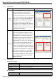
DeviceNet Network Scanner DVPDNET-SL 1.3 I/O Scan List Item Explanation Software screen Before DVPDNET-SL starts its operation, you have to configure its scan list through the configuration software. The scan list is a list consisting of the information of slave devices with data, e.g. slave address, I/O type, I/O data length Scan Table and so on, to be exchanged with DVPDNET-SL.
DeviceNet Network Scanner DVPDNET-SL Electrical specification Voltage 11 ~ 25 VDC supplied by the power cable in the network Current 28mA (typical), 125mA impulse current (24 VDC) Environment 2 Noise immunity ESD (IEC 61131-2, IEC 61000-4-2): 8KV Air Discharge EFT (IEC 61131-2, IEC 61000-4-4): Power Line: 2KV, Digital I/O: 1KV Analog & Communication I/O: 1KV Damped-Oscillatory Wave: Power Line: 1KV, Digital I/O: 1KV RS (IEC 61131-2, IEC 61000-4-3): 26MHz ~ 1GHz, 10V/m Operation 0ºC ~ 55ºC (temperat
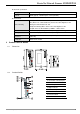
DeviceNet Network Scanner DVPDNET-SL 2.3 DeviceNet Connection Port The connector is used on the connection to DeviceNet. Wire by using the connector enclosed with DVPDNET-SL. 2.4 PIN Signal Color Content 1 V- Black 0 VDC 2 CAN_L Blue Signal- 3 SHIELD - Shielded 4 CAN_H White Signal+ 5 V+ Red 24 VDC 5 4 3 2 1 Address Switch The switch is used on setting up the node address of DVPDNET-SL on DeviceNet. Range: 00 ~ 63 (64 ~ 99 are forbidden).
DeviceNet Network Scanner DVPDNET-SL DVPDNET-SL. z When DVPDNET-SL is operating, changing the setting of the function switch will be invalid. z Use slotted screwdriver to adjust the DIP switch carefully in case you scratch the switch. 2.6 Digital Indicator The digital indicator provides the following two functions: DVPDNET POWER MS NS 1. Displaying the node address and error messages of DVPDNET-SL and error messages. 2. Displaying the error message of slave. 2.
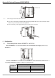
DeviceNet Network Scanner DVPDNET-SL DVPDNET DVP28SV 35mm DIN rail RUN STOP 3.3 Connecting to DeviceNet Connection Port The colors on the PINs on the DeviceNet connection port match the colors of the connection cables. Make sure you connect the cable to the right PIN. We recommend you also apply Delta’s power module in the connection. 4 Configuration 4.
DeviceNet Network Scanner DVPDNET-SL 4.
DeviceNet Network Scanner DVPDNET-SL DVP-PS01 DVP28SV DVPDNET-SL DVPDNET DVP28SV DeviceNet network configuration tool L N 0V RUN STOP Node 01 RS-232 DeviceNet Node 03 Node 02 X0 P O RT1 X1 PO RT2 L Y0 DVP-16SP 0V R TU- DN ET N IFD9502 DVP-PS01 VFD-B RTU-DNET DVP-16SP 2. Set up DVPDNET-SL, DNA01 and RTU-DNET according to the table below. 5.
DeviceNet Network Scanner DVPDNET-SL (3) Set up the communication parameters in the PC and DVP-SV, e.g. the communication port, address, baud rate and communication format.
DeviceNet Network Scanner DVPDNET-SL (5) Click on “OK”, and DeviceNetBuilder will start to scan the entire network. (6) If the bar on the dialog box does not progress, it means the connection between the PC and DVP-SV is abnormal, or there are other programs also using the COM port on the PC. After the scan is completed, the dialog box will tell you that the scan is completed, and the icons and device names of all the nodes scanned on the network will be shown on the screen.
DeviceNet Network Scanner DVPDNET-SL (8) Click on “IO Configure…” button in “Node Configuration” dialog box, and you will then see “RTU Configuration” page. (9) Click on “Scan IO”, and the "Warning” dialog box will appear. (10) Click on “OK”. DeviceNetBuilder will then detect the special I/O module connected to RTU-DNET and the number of points in the digital I/O module and display the information on "RTU Configuration” page.
DeviceNet Network Scanner DVPDNET-SL (11) Double click on RTU-DNET icon, and you will then see “RTU Setup” dialog box. (12) Set up the parameters in RTU-DNET and confirm its I/O information. Item Function Default The sum of the length of the status word of RTU-DNET and the input data of the I/O module connected to it. The status Input IO Data Length word of RTU-DNET occupies 2 bytes. One input channel of N/A the special I/O module occupies 2 bytes.
DeviceNet Network Scanner DVPDNET-SL Item Function Default The digital output points shall be 8’s multiple. The number will DIDO Output Points (Y) be regarded as 8 when it is less than 8 and regarded as 16 N/A when it is bigger than 8 but less than 16. AIAO Module Number The number of special I/O modules connected to RTU-DNET. Diagnostic Intervel Time The interval when RTU-DNET executes diagnosis.
DeviceNet Network Scanner DVPDNET-SL (16) Confirm the parameters and I/O data in VFD-B and click on “OK”. 2. Configuration of DVPDNET-SL (1) Double click on DNET Scanner (node 01), and the “Scan Module Configuration..." dialog box will appear. You can find the currently available nodes, RTU-DNET and VFD-B Drives 230V 3HP, in the list on the left side. On the right side, there is an empty “Scan List”.
DeviceNet Network Scanner DVPDNET-SL (3) Confirm all the settings and click on “OK”. Next, download the configuration to DVPDNET-SL. If DVP-SV is in RUN mode while you are downloading the configuration, a “Warning” dialog box will appear. (4) Click on “OK” to continue the download. Make sure DVP-SV is in RUN mode. Follow the steps given above to configure DeviceNet network.
DeviceNet Network Scanner DVPDNET-SL Slave → DVPDNET-SL Register in DVPDNET-SL D6037H Devices in slave Digital I/O module X0 ~ X7 on DVP-16SP D6037L N/A D6038H Status of LED on VFD-B D6038L Status of VFD-B AC motor drive D6039H High byte of frequency in VFD-B D6039L Low byte of frequency in VFD-B If the I/O data include control word and status word of RTU-DNET, the I/O data mapping of DVPDNET-SL and its slave devices will be: DVPDNET-SL → slave Register in DVPDNET-SL D6287H Devices in slave
DeviceNet Network Scanner DVPDNET-SL Target 1. When X0 = On, VFD-B will start to run, and Y0 indicator will be On. When X1 = On, VFD-B will stop, and Y0 indicator will be Off. PLC program: M1000 MOV D6037 K4M0 Send the content in D6037 to K4M0. MOV D6038 K4M20 Send the content in D6038 to K4M20. MOV H2 D6288 When X0 = On, start VFD-B. MOV H1 D6288 When X1 = On, stop VFD-B. MOV H0100 D6287 When VFD-B runs, Y0 = On. MOV H0000 D6287 When VFD-B stops, Y0 = Off.
DeviceNet Network Scanner DVPDNET-SL 6 Sending Explicit Message from Ladder Diagram DVPDNET-SL supports the sending of explicit messages through WPL programs. 6.
DeviceNet Network Scanner DVPDNET-SL 1. Structure of request message See the table below: Request Message PLC device 15 14 13 12 11 10 9 D6250 8 7 6 5 4 3 2 1 ReqID Command Port Size D6252 Service Code MAC ID D6253 High byte of Class ID Low byte of Class ID High byte of Instance ID Low byte of Instance ID Reserved Attribute ID (optional) D6251 D6254 Message Header Message Data D6255 D6256 ~ D6281 0 Service Data Command: Fixed to “01Hex”. ReqID: The request ID.
DeviceNet Network Scanner DVPDNET-SL Status Explanation 0 No explicit message is sent out. 1 The communication of explicit message is successful. 2 The explicit message is being sent out. 3 Error: No response from the target equipment. 4 Error: Command is invalid. 5 Error: Size of request message is invalid. 6 Error: Size of reponse message is invalid. 7 Error: Failing to establish a connection to the target equipment. 8 ~ 255 Reserved 3.
DeviceNet Network Scanner DVPDNET-SL Compulsory settings in IFD9502 Parameter Set value Node address 02 Baud rate 500kbps Explanation Set the node address of IFD9502 to “02". Set the communication speed of IFD9502 and bus to “500kbps”. Compulsory settings in VFD-B Parameter Set value Explanation 02-00 04 The main frequency is operated on RS-485 interface. 02-01 03 The operation commands are operated on the communication interface. Operation by keys is valid.
DeviceNet Network Scanner DVPDNET-SL (4) Program explanations: In the beginning of the program, clear the response message editing area and request message editing area to 0. When M0 = On, DVPDNET-SL will send out request message, reading Class 1>>Instance 1>> Attribute 1 of the target equipment (node address: 02). If the communication of explicit message is successful, the slave will return with a response message. When M0 = On, DVPDNET-SL will only send out request message once.
DeviceNet Network Scanner DVPDNET-SL Parameter Set value Explanation 02-01 03 The operation commands are operated on the communication interface. Operation by keys is valid. 09-00 01 Communication address of VFD-B: 01 09-01 03 Baud rate: 38,400 09-04 03 Modbus RTU mode.
DeviceNet Network Scanner DVPDNET-SL editing area to 0. When M1 = On, DVPDNET-SL will send out request message. Write 0004Hex into Class 99 >> Instance 1 >> Attribue 2 of the target equipment (node address: 02). If the communication of explicit message is successful, the slave will return with a response message. When M1 = On, DVPDNET-SL will only send out request message once. If you would like it to send out request message again, you will have to change ReqID.
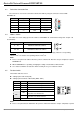
DeviceNet Network Scanner DVPDNET-SL Corresponding nodes on the network PLC device b15 b14 b13 … b1 b0 D6032 Node 15 Node 14 Node 13 … Node 1 Node 0 D6033 Node 31 Node 30 Node 29 … Node 17 Node 16 D6034 Node 47 Node 46 Node 45 … Node 33 Node 32 D6035 Node 63 Node 62 Node 61 … Node 49 Node 48 When the node in the scan list is normal, the corresponding bit will be Off. If the node occurs abnormality, its corresponding bit will be On. 8.
DeviceNet Network Scanner DVPDNET-SL LED status Indication Red light blinking Red light on 9.3 Error in communication Check the digital indicator and eliminate the error. Network error; cannot check duplicate ID; bus-off (chek the digital indicator) 1. Make sure all the devices have their unique node address. 2. Check the network for correcting media installation and baud rate. 3. Check if the node address of DVPDNET-SL is valid. 4. Check if the network power is normal.
DeviceNet Network Scanner DVPDNET-SL Code Indication How to correct F2 Low voltage is detected. Check if the power of DVPDNET-SL and PLC MPU is normal. F3 Entering test mode Switch IN1 from On to Off and re-power DVPDNET-SL. F4 Bus-off 1. Check if the network cable is normal. 2. Check if the baud rate is correct. 3. Re-power DVPDNET-SL. F5 No network power Make sure the cable is correctly connected and check if the network power is normal.
DeviceNet Network Scanner DVPDNET-SL MEMO 30 DVP-PLC Operation Manual