2Wire Gateway Installation Guide For 2701HGV-W
Notice to Users ©2008 2Wire, Inc. All rights reserved. This manual in whole or in part, may not be reproduced, translated, or reduced to any machinereadable form without prior written approval. 2WIRE PROVIDES NO WARRANTY WITH REGARD TO THIS MANUAL, THE SOFTWARE, OR OTHER INFORMATION CONTAINED HEREIN AND HEREBY EXPRESSLY DISCLAIMS ANY IMPLIED WARRANTIES OF MERCHANTABILITY OR FITNESS FOR ANY PARTICULAR PURPOSE WITH REGARD TO THIS MANUAL, THE SOFTWARE, OR SUCH OTHER INFORMATION, IN NO EVENT SHALL 2WIRE, INC.
Contents Getting Started . . . . . . . . . . . . . . . . . . . . . . . . . . . . . . . . . . . . . . . . . . . . . . . . . . . . . 1 Remove or Disable Conflicting Applications . . . . . . . . . . . . . . . . . . . . . . . . . . . . . . . . . . 1 Check Your Computer’s Browser and System Requirements . . . . . . . . . . . . . . . . . . . . . . 1 Browser Requirements . . . . . . . . . . . . . . . . . . . . . . . . . . . . . . . . . . . . . . . . . . 1 System Requirements . . . . . . . . . . . . . . . . . . . .
Getting Started Remove or Disable Conflicting Applications Internet sharing software and PC based firewall applications typically interfere with the 2Wire gateway, and should be removed or disabled before you install the gateway. The 2Wire gateway provides the same features as the products listed below. If you have any of the following (or similar) applications installed on your computers, remove or disable them according to the manufacturer’s instructions before proceeding.
Connect the First Computer to the Gateway Congratulations on the purchase of your 2Wire gateway. To install your gateway and configure your network, follow these steps. Note: Features for different models may vary. Product details will be specified for each particular model. Choose a Computer and Connection Type There are many ways to set up your network, but typically the first computer is located in the same room as the gateway and your DSL connection.
Connect the First Computer to the Gateway To install the DSL filter: 1. Locate the phone jack where you want to connect your 2Wire gateway. 2. Insert the DSL filter into the jack. 3. If you have a phone, answering machine, fax machine, satellite TV equipment, or other phone device in this jack location, plug it into the filter port labeled PHONE. 4. Install a DSL filter on all other phone devices in your house (such as dial-up modems, fax machines, caller ID devices, and set top boxes).
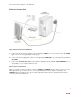
Connect the First Computer to the Gateway Ethernet Connection Figure 1. Gateway Connected Via Ethernet 1. Connect the provided power adapter from the gateway’s POWER port to an electrical outlet. The POWER light on the front of the gateway should be green. 2. Connect the provided gray phone cable from the gateway’s PHONE LINE port to the DSL filter jack labeled DSL/HPNA. 3.
Connect the First Computer to the Gateway Wireless Connection Requires wireless-enabled notebook or a computer with an 802.11b/g wireless network adapter installed. Wireless adapters can be purchased from your service provider. Note: Security of the 802.11g wireless connection associated with this 2Wire 2701HGV-W ADSL2+ Router is the customer’s responsibility.
Connect the First Computer to the Gateway Non-2Wire Wireless Adapter Configuration Locating the Serial Number and Wireless Encryption Key The serial number of your 2Wire gateway is used as the network name (SSID). Beneath the serial number is a ten-digit number which is used as the encryption key. These are located on the bottom of your gateway (shown in horizontal orientation). You will need this information to configure your wireless adapter. Configuring the Adapter 1.
Connect the First Computer to the Gateway USB Connection Figure 3. Gateway Connected Via USB 1. Connect the provided AC power adapter from the 2Wire gateway’s POWER port to an electrical outlet. The POWER light on the front of the gateway should be green. 2. Connect the provided blue USB cable from the gateway’s USB port to the USB port on your computer. 3. Connect the provided gray telephone cable from the gateway’s PHONE LINE port to a telephone jack with DSL service.
Connect the First Computer to the Gateway Install the 2Wire Gateway USB Driver - Windows 1. Power on your computer and place the 2Wire CD in your computer’s CD-ROM drive. 2. If the Add Hardware Wizard displays, follow the on-screen instructions. If prompted to identify where to search for drivers, deselect Floppy Disk drive and check CD-ROM drive. 3. After the driver installs click Finish to complete the driver installation. The Setup Wizard will resume when your PC has rebooted.
Run the 2Wire Setup Wizard Windows XP/2K/ME/98SE 1. 2. Insert the 2Wire CD and follow the on-screen instructions. If the 2Wire Setup Wizard does not automatically start: − Double-click the My Computer icon located on the desktop. − Double-click the icon that corresponds to your CD-ROM drive. − Double-click Setup.exe and follow the on-screen instructions. If prompted by the Setup Wizard, enter the 20-digit key code you received from your service provider.
Add Computers to the Network After your first computer is connected to the 2Wire gateway and your Internet connection has been established, you can connect other computers to the network. Use any of the following methods to connect additional computers to your network.
Add Computers to the Network Ethernet Connection Figure 4. Gateway Connected to Second Computer Via Ethernet 1. Connect an Ethernet cable from the any available LOCAL ETHERNET1 port on the gateway to your computer’s Ethernet port. 1. The number of Ethernet ports vary by model (from one to four). If your gateway has four Ethernet ports, you can connect up to four computers to your network via Ethernet.
Add Computers to the Network USB Connection Figure 5. Gateway Connected to Second Computer Via USB 1. Connect the provided blue USB cable from the gateway’s USB-PC port to the USB port on your computer. 2. Install the USB driver (refer to page 8 for instructions). 3. Repeat “Run the 2Wire Setup Wizard” on page 9.
Add Computers to the Network Wireless Connection Figure 6. Gateway Connected to Second Computer Via Wireless Requires a computer with an 802.11b/g wireless network adapter installed. Wireless adapters are purchased separately from the 2Wire gateway. Note: If you use a 2Wire wireless adapter (PCI, PC card, or USB adapter) for wireless networking, the gateway installation software automatically configures it to communicate with the gateway during setup.
Diagnostics Note: Broadband Redirect Messages are visible only if they have been enabled by your service provider, and the physical appearance may vary from the examples shown. Understanding Broadband Redirect Messages If the 2Wire gateway detects a connection problem or an intermittent service error, it generates an error or alert (Broadband Redirect Message) and displays the message within your Web browser.
Diagnostics No DSL Connection - Unable to Train When setting up a DSL broadband network, all active phone devices must have a phone line filter installed. Without the filter, the DSL connection will be unstable, resulting in a poor or no DSL connection. If phone line filters are missing, line noise and/or echo can affect the DSL connection. This error message occurs when the noise level is so high that the gateway cannot establish a DSL connection.
Diagnostics Broadband Link is Currently Not Available - DSL Connection Issue This error message is displayed because the gateway was unable to establish a broadband network connection. Check to ensure that all cables are correctly connected, and the cable end securely attached to the port. In addition, verify that you are connecting on or after the date specified by your service provider for DSL service availability.
Diagnostics Router Behind Router Detected If the gateway detects the presence of a third-party router, the Router Behind Router error page displays. If a third-party router is connected to the 2Wire gateway, network instability can result because both devices are trying to manage private IPs via NAT. The best solution is to remove the third-party router from your LAN since the 2Wire gateway can manage your home network.
Diagnostics Understanding the Indicator Lights The 2Wire gateway has numerous indicator lights that can be used to diagnose installation and connection problems. The following table describes how to interpret the indicator lights. Power Light Operating State OFF The gateway is not getting power. Blinking green (slow) The gateway is undergoing POST (power-on self test). Solid green Power is on. Blinking orange The gateway is undergoing a software upgrade. Solid red System error.
Diagnostics Phone Lights Operating State Not used on this model Not used on this model DSL Light Operating State OFF The gateway is powered off or booting up. Blinking green (slow) The gateway is attempting to establish a connection to your broadband service(s). Blinking green (fast) The gateway has been unable to connect to the DSL signal for more than three minutes. Solid green The gateway is fully connected to your broadband service(s).
Appendix A: Install the Gateway on Other Operating Systems Follow these instructions if you are using an operating system that is not supported by the 2Wire CD (such as any Macintosh OS prior to 10.2, UNIX, or Linux). There are many ways to set up your network, but typically the first computer is located in the same room as the gateway and your DSL connection. Ethernet is the preferred connection method for your first computer, although instructions for connecting via USB are also provided.
Appendix A: Install the Gateway on Other Operating Systems 4. Connect the yellow Ethernet cable provided with the gateway from a LOCAL ETHERNET port on the gateway to your computer’s Ethernet port. 5. Proceed to “Configuring the Internet Connection” on page 22. USB Connection Note: Connecting your computer to the gateway using USB requires an available USB port. Only one Windows or Macintosh computer can be directly connected to the 2Wire gateway using the USB connection.
Appendix A: Install the Gateway on Other Operating Systems 6. Follow the on-screen instructions. When the driver installation is complete, you will be prompted to restart your computer. 7. After your computer restarts, connect the provided blue USB cable from the USB-PC port on the 2Wire gateway to your computer’s USB port. 8. Open the network Control Panel by selecting the Apple icon > Control Panel > TCP/IP. 9.
Regulatory Information Electrical AC Adapter The AC adapter is designed to ensure your personal safety and to be compatible with this equipment. Please follow these guidelines: • Do not use the adapter in a high moisture environment. Never touch the adapter when your hands or feet are wet. • Allow adequate ventilation around the adapter. Avoid locations with restricted airflow. • Connect the adapter to a proper power source. Voltage and grounding requirements are found on the product case and/or packaging.
Regulatory Information This equipment has been tested and found to comply with the limits for a Class B digital device, pursuant to part 15 of the FCC Rules. These limits are designed to provide reasonable protection against harmful interference in a residential installation. This equipment generates, uses and can radiate radio frequency energy and, if not installed and used in accordance with the instructions, may cause harmful interference to radio communications.
Regulatory Information MPE/SAR Labeling WARNING: While this device is in operation, a separation distance of at least 20 cm (8 inches) must be maintained between the radiating antenna inside the Equipment Under Test (EUT) and the bodies of all persons exposed to the transmitter in order to meet the FCC RF exposure guidelines. Making changes to the antenna or the device is not permitted. Doing so may result in the installed system exceeding RF exposure requirements.