F-116 / F-116P Field Engineering Manual U.S.A. version 1.1 Muratec America, Inc. 3301 East Plano Parkway, Ste. 100 Plano, TX 75074 (469) 429-3300 (tel) (469) 429-3465 (fax) www.muratec.
Contents chapter 1 Precautions 1.1 Safety Warning……………………………………………………… 1.2 Caution for safety…………………………………………………… 1.2.1 Toxic material…………………………………………………… 1.2.2 Electric Shock and Fire Safety Precautions… ……………… 1.2.3 Handling Precautions… ……………………………………… 1.2.4 Assembly / Disassembly Precautions………………………… 1.2.5 Disregarding this warning may cause bodily injury… ……… 1.3 ESD Precautions… ………………………………………………… 1-1 1-2 1-2 1-2 1-3 1-3 1-4 1-5 chapter 2 Product Overview 2.
Contents 3.2 Screws used in the printer… ……………………………………… 3.3 White Roller… ……………………………………………………… 3.4 Front Cover… ……………………………………………………… 3.5 Rear cover…………………………………………………………… 3.6 Scan Ass’y … ……………………………………………………… 3.6.1 OPE unit … …………………………………………………… 3.6.2 Scan Drive unit ………………………………………………… 3.6.3 ADF roller … …………………………………………………… 3.6.4 CIS… …………………………………………………………… 3.7 Right/Left Cover… ………………………………………………… 3.8 Fuser Unit… ………………………………………………………… 3.9 Drive unit… ………………………………………………………… 3.
Contents 4.2 Troubleshooting…………………………………………………… 4.2.1 Procedure of Checking the Symptoms… …………………… 4.2.2 The cause and solution of Bad image… …………………… 4.2.3 The cause and solution of the bad discharge… …………… 4.2.4 The cause and solution of the malfunction… ……………… 4.2.5 The cause and solutions of bad environment of the software… ………………………… 4.2.6 Fax & Phone Problems… …………………………………… 4.2.7 Copy Problems………………………………………………… 4.2.
attached Exploded Views & Parts List * Avaiable on the Muratec Technical Support web site.
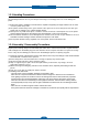
Precautions 1. Precautions In order to prevent accidents and to prevent damage to the equipment please read the precautions listed below carefully before servicing the printer and follow them closely. 1.1 Safety Warning (1) Only to be serviced by appropriately qualified service technician. High voltages and lasers inside this product are dangerous. This printer should only be serviced by a qualified service technician.
Precautions 1.2 Caution for safety 1.2.1 Toxic material This product contains toxic materials that could cause illness if ingested. (1) If the LCD control panel is damaged it is possible for the liquid inside to leak. This liquid is toxic. Contact with the skin should be avoided, wash any splashes from eyes or skin immediately and contact your doctor. If the liquid gets into the mouth or is swallowed see a doctor immediately. (2) Please keep Drum cartridge and Toner Cartridge away from children.
Precautions 1.2.3 Handling Precautions The following instructions are for your own personal safety, to avoid injury and so as not to damage the printer (1) Ensure the printer is installed on a level surface, capable of supporting its weight. Failure to do so could cause the printer to tip or fall. (2) The printer contains many rollers, gears and fans. Take great care to ensure that you do not catch your fingers, hair or clothing in any of these rotating devices.
Precautions 1.2.5 Disregarding this warning may cause bodily injury (1) Be careful with the high temperature part. The fuser unit works at a high temperature. Use caution when working on the printer. Wait for the fuser to cool down before disassembly. (2) Do not put finger or hair into the rotating parts. When operating a printer, do not put hand or hair into the rotating parts (Paper feeding entrance, motor, fan, etc.). (3) When you move the printer. This printer weighs 8.
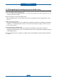
Precautions 1.3 ESD Precautions Certain semiconductor devices can be easily damaged by static electricity. Such components are commonly called “Electrostatically Sensitive (ES) Devices” or ESDs. Examples of typical ESDs are: integrated circuits, some field effect transistors, and semiconductor “chip” components. The techniques outlined below should be followed to help reduce the incidence of component damage caused by static electricity.
Precautions 1-6
Product specification and feature 2. Product specification and feature 2.1 Product Specifications 2.1.1 Product Overview F-116P : Fax, Copy, Print, Scan F-116 : Fax, Copy 1. Print Speed (F-116P only) • 19 ppm in Letter 2. Copy Speed • 19 ppm in Letter 3. Processor • Chorus2 66 Mhz 4. Interfaces • One USB port 6. Toner cartridge • Initial : 1K starter cartridge • Replacement : 2.
Product specification and feature 2.1.2 Specifications • Product Specifications are subject to change without notice. See below for product specifications. 2.1.2.1 General Specifications Item F-116 F-116P Major Features Fax, Copier, Phone Fax, Copier, Print, Scan, Phone Size (W*D*H) with Hand Set 293.7 x 391.2 x 360 mm 293.7 x 391.2 x 360 mm Weight (Inculding Toner Cartridge) 8.9 change to lbs 8.9 change to lbs I/O Interface USB - Firmware update only USB.1.1 & USB2.
Product specification and feature Item Driver F-116 F-116P Printer N/A GDI TWAIN, WIA N/A Yes PSU N/A Yes SmarThru4 N/A Yes Smart Panel N/A Yes Less than 9 seconds Less than 9 seconds Print 10,000 pages 10,000 pages ADF 2,000 pages 2,000 pages Average Monthly Print Volume Print : 500 pages, ADF : 500 pages Print : 500 pages, ADF : 500 pages Machine Life 50,000 pages 50,000 pages Operating 10~32 change to degrees F 10~32 change to degrees F Non Operating -20~40 change to
Product specification and feature 2.1.2.3 Scan Specifications Item F116 Scan Method Scan Speed through ADF Resolution N/A Color CIS Gray Mode N/A 72 sec Color 300dpi N/A Yes Color 75dpi N/A Yes Optical N/A 600*600dpi Enhanced N/A 600dpi N/A 256 level N/A Max.216mm(8.5") Halftone Scan Size F116P Max.
Product specification and feature 2.1.2.
Product specification and feature 2.1.2.6 Fax Specifications Item F-116 F-116P Compatibility ITU-T G3 ITU-T G3 Communication System PSTN/PABX PSTN/PABX Modem Speed 33.6K bps 33.6K bps TX Speed 3 sec 3 sec Compression MH/MR/MMR MH/MR/MMR ECM Yes Yes Std 203 x 98dpi 203 x 98dpi Fine 203 x 196dpi 203 x 196dpi S.
Product specification and feature 2.1.2.
Product specification and feature 2.1.2.
Product specification and feature 2.1.3 Model Comparison Table F-116P (Muratec) Model LJ-M1319f (HP) MFC-7225N (Brother) 4-in-1 (Print, Scan, Copy, Fax) Type Image RTS ’10. Jan Speed (Ltr) Print Copy 19ppm '08. Mar '05. Jun 18ppm 20ppm Resolution 600 x 600 dpi 1,200 x 1,200 dpi 2,400 x 600 dpi Emulation SPL GDI PCL, PS3 FPOT 10 sec from ready 8.
Product specification and feature 2.2 System Overview This chapter describes the functions and operating principal of the main component. 2.2.
Product specification and feature 2.2.
Product specification and feature 2.2.3 System Layout This model is consisted of the Engine parts and F/W, and said engine parts is consisted of the mechanical parts comprising Frame, Feeding, Developing, Driving, Transferring, Fusing, Cabinet and H/W comprising the main control board, power board, operation panel, PC Interface.
Product specification and feature 2.2.3.1 Feeding Part It is consists of a basic cassette, an MP tray for supplying different types of media (envelope, label, special paper) and parts related to paper transferring. 1) Separation method Paper is separated by the friction pad mounted to the center of the cassette. 2) Basic cassette It takes a center loading method and applies ‘friction pad separating method.
Product specification and feature 2.2.3.2 Transfer Assy - The transfer roller delivers the toner from the OPC drum to the paper. - There is no PTL Ass’y. - Life Span : Print over 50,000 sheets (in15~30 change to degrees F) 2.2.3.3 Driver Assy - The driving device is consisted of step motor, OPC, Pick- up, Feed, gear block all mounted as an assembly.
Product specification and feature 2.2.3.4 Fuser It is consists of a halogen lamp, heat roller, pressure roller, thermistor and thermostat. It fuses the toner on to the paper by heat and pressure to complete the printing job. 1) Thermostat When a heat lamp is overheated, a Thermostat cuts off the main power to prevent over- heating. - Thermostat Type : Non- Contact type THERMOSTAT - Control Temperature : 170℃ ± 5℃ 2) Thermistor It is a temperatrue detecting sensor.
Product specification and feature 6) Items for safety Protecting device for overheating - 1st protection device: Hardware cuts off when overheated - 2nd protection device: Software cuts off when overheated - 3rd protection device: Thermostat cuts off main power. Safety device - A fuser power is cut off when a front cover is opened - Maintain a temperature of fuser cover’s surface under 80℃ for user, and attach a caution label at where customer can see easily when customer open a rear cover.
Product specification and feature 2.2.3.5 LSU (Laser scanning unit) It is the core part of the LBP which switches the video data received to the controller to the electrostatic latent image on the OPC drum by controlling laser beam, exposing OPC drum, by use of a polygon mirror. of polygon mirror. The OPC drum is synchronized with the paper feeding speed. The /HSYNC signal is created when the laser beam from LSU reaches the end of the polygon mirror, and the signal is sent to the controller.
Product specification and feature 2.2.3.6 Toner Cartridge By using the electronic photo process, it creates a visual image. In the toner cartridge, the OPC unit and the developing unit are contained in one assembly. The OPC unit houses the OPC drum and charging roller, and the toner cartridge unit has toner, supply roller, developing roller and blade (Doctor blade) • Developing Method : Non magnetic 1 element contacting method • Toner : Non magnetic 1 element shatter type toner • Charging capacity : - 39.
Product specification and feature 2.2.4 Engine H/W Specifications 2.2.4.1 Main PBA The Engine and the Printer Controller function are housed into one Main Board called Main PBA. The CPU is functioned as the bus control, I/O handling, drivers, and PC interface. The main board sends the Current Image of Video data to the LSU and manages the electrophotography for printing.
Product specification and feature 1) CPU se S3C46Q0X 16/32-bit RISC micro controller, Chorus 2,which is exclusive controller to execute Printer & U FAX Function and to execute operation block by flash memory within system program, and to control whole system. - 1.8V internal, 3.
Product specification and feature 4) Sensor Input Circuit ■ Paper Empty Sensing & Paper Width Sensor When a printing job comes to the CPU, the CPU initializes the pickup action regardless of the state of the sensor. If paper is then detected by the Feed Sensor, the paper will then be recognized as e.g. invoice paper even though the Paper Empty Sensor was on.
Product specification and feature 2.2.4.2 HVPS and SMPS Board The HVPS Board and SMPS Board housed in one board. The HVPS board creates the high voltage of THV/MHV/Supply/Dev and supplies it to the developer portion takes the 24V and outputs the high voltage for THV/MHV/BIAS, and supplied to the high voltage, OPC cartridge, and transfer roller for optimum latent image and toner transfer quality.
Product specification and feature ■ HVPS Board • Transfer High Voltage (THV+) - Input Voltage : 24 V DC ± 15% - Output Voltage : MAX +5.0KV ± 5 %,(Duty Variable, no loading) - 1.2KV ±15% (when cleaning,200 ㏁) - Input contrast of the Voltage stability degree : under ± 3 % (fluctuating input 21.6V~26.
Product specification and feature • Supply - Output Voltage : - 400 V ~ - 800V DC ±50 V(ZENER using, DEV ) - Input contrast of the output stability degree : under ± 5 % Loading contrast : ± 5 % or less - Output Voltage Rising Time : 50 ms Max - Output Voltage Falling Time : 50 ms Max - Output Loading range : 10 MΩ ~ 1000 MΩ - Output Control Signal (BIAS- PWM) : the CPU is HV output when PWM is low.
Product specification and feature 2.2.4.3 Fax Our fax feature is based on Conexant DAA (Data Access Arrangement) Solution, and is controlled by a dual Chip Set Solution. - CX86710 (SFX336) : This Modem Chip adds SSD (System Side Device) for interfacing between LSD and DIB of FM336Plus Core - CX20493 (LSD) : This Modem Chip LIU (Line Interface Unit) is controlled by SSD and satisfies each PSTN requirement by modulating the internal configuration with connecting Tel Line.
Product specification and feature 2.2.4.4 Scan 1) Pictorial signal input part: output signal of CIS passes through MP Cap change to ADC at LAFE1001, and defined signal between LAFE1001 and JUPITER5 processes the Image signal. When AFE accepts each pixel, CDS (Correlated Double Sampling ) technique which samples arm-level twice is used on each pixel by the CIS signal.
Product specification and feature 2.2.5 Engine F/W Contol Algorithm 2.2.5.1 Feeding If feeding from a cassette, the drive to the pickup roller is controlled by a solenoid. The on/off time the solenoid is controlled by Main PBA. The Paper Jam protocols are as follows: Item Description JAM 0 - After picking up, paper cannot be entered due to paper is not fed. - After picking up, paper does not reach the Feed Sensor in after a predetermined time due to paper slippage, etc.
Product specification and feature 2.2.5.3 Fusing The temperature change of the heat roller’s surface is changed to the resistance value through the thermistor. The Heat Roller temperate (warmup) is measured by converting the resistance of the thermistor to a measurable DC voltage value. The AD converter changes it to a digital value so it knows when it has reach its proper fusing temperature. The AC power to the fuser lamp is controller by comparing the target temperature to the value from the thermistor.
Product specification and feature 2.2.6 S/W Descriptions 2.2.6.1 Overview The software system is constructed as follows: 1) The Host Software is an application software that can operate in a Windows and/or Web Environment. 2) The Firmware portion is an Embedded software controlling the print job. 2.2.6.2 Architecture Host Software is made up of: 1. Graphic User Interface that offers the various editing functions to user in Host. 2.
Product specification and feature 2.2.6.3 Data and Control Flow . GDI & PCL6 (PCL XL) Provided below is a detail explanation of the Block Diagram above. Host Side is made up of: 1. The Print Driver that is Windows application softwares translate printed data to one of printer languages and creates spooler file. 2.
Product specification and feature Firmware Side is made up of: 1. Network Interface Card is that relay the communication between Host and kernel using various network protocols. 2. Kernel manages the flow control of emulation procedure, receiving data from Host or Network card and printing with engine & rendering job. 3. Emulation interprets the various output data from selected emulation. 4. Engine prints rendered bit-map data to paper with required size and type by Kernel.
Product specification and feature 2-32
Disassembly and Reassembly 3. Disassembly and Reassembly 3.1 Precautions when replacing parts 3.1.1 Precautions when assembling and disassembling *U se only approved spare parts. Ensure that part number, product name, any voltage, current or temperature rating are correct. Failure to do so could result in damage to the machine, circuit overload, fire or electric shock.
Disassembly and Reassembly 3.2 Screws used in the printer The screws listed in the table below are used in this printer. Please ensure that, when you disassemble the printer, you keep a note of which screw is used for which part and that, when reassembling the printer, the correct screws are used in the appropriate places.
Disassembly and Reassembly 3.3 White Roller 1. Open the OPE Unit. 2. Pull the lever up on the right end of the white roller. Then lift the roller out.
Disassembly and Reassembly 3.4 Front Cover 1. Take out the Cassette. 2. Open the front cover. Unlatch the front cover from the Frame assy. 3.5 Rear cover Remove 4 screws securing the rear cover and remove it.
Disassembly and Reassembly 3.6 Scan Ass’y 1. Before removing Scan Ass’y, remove the rear cover. 4. Remove all connectors and 1 screw. 2. Open the front cover. And remove 2 screws from the front. 5. Remove 1 screw. Then lift the Scan Assy up. 3. Remove the harness cover [A] from the rear after removing 1 screw.
Disassembly and Reassembly 3.6.1 OPE unit 1. Open the OPE unit. And release the latch from holder. 3. Remove 2 screws. 4. Open the OPE bottom cover. Release the OPE PBA after removing 1 connector and 2 screws. 2. Carefully release the latches from both side of OPE unit.
Disassembly and Reassembly 3.6.2 Scan Drive unit 1. Remove the OPE unit. (Refer to 3.6.1) Then remove 4 screws. 3. Remove 2 screws. 4. Unplug the connector. Then release the scan drive unit. 2. Open the Scan Cover.
Disassembly and Reassembly 3.6.3 ADF roller 1. Remove the Scan Drive unit. 2. Release the ADF roller as shown below. 3.6.4 CIS 1. Remove the white roller. 2. Release the CIS after unlatching both side holder.
Disassembly and Reassembly 3.7 Right/Left Cover 1. Remove the front cover and rear cover. (Refer to 3.4, 3.5) 2. Remove the Scan Assy. (Refer to 3.6) 3. Remove the Left/ Right cover by removing hooks of right/left/top/bottom side.
Disassembly and Reassembly 3.8 Fuser Unit 1. Remove the rear cover. 2. Remove 4 screws. 3. Unplug the 2 connectors from SMPS board and Main board. 4. Take off the Fuser unit.
Disassembly and Reassembly 3.9 Drive unit 1. Remove the Rear cover/ Scan Assy / Left cover. 3. Take off the Drive Unit after removing 1 connector. 2. Remove 6 screws. 3.10 Solenoid 1. Remove the Drive unit (refer to 3.9) 5. Remove the gears. 2. Remove the solenoid connector on Main PBA. (refer to 3.1.14) 6. Take off the solenoid [B] after removing 1 screw. 3. Take off the solenoid [A] after removing 1 screw. 4. To remove the solenoid [B], take off the bracket after removing 3 screws.
Disassembly and Reassembly 3.11 FAN 1. Remove the right cover. 2. Remove 1 screw and 1 connector. 3. Take off the FAN.
Disassembly and Reassembly 3.12 LSU 1. Remove the Rear cover/ Scan Ass’y 2. Lift the LSU unit off by removing 3 screws and 2 connectors.
Disassembly and Reassembly 3.13 Transfer Roller 1. Open the front cover. 2. Take out the toner cartridge. 3. Take off the transfer roller by release its right shaft from hook. Transfer roller Caution Don’t touch the surface of tranfer roller.
Disassembly and Reassembly 3.14 Main PBA and SMPS/HVPS board 1. Take out the Cassette unit. 2. Remove Front cover / Rear cover / Scan Ass’y / Right cover. (refer to 3.4~3.7) 3. Remove 10 screws (bottom x 9 , rear x 1 ) and 2 connector. (SMPS x 1 , Fan x 1) 4. Turn the board shield over. 5. Remove 5 screw and unplug all connectors on Main PBA. Then release the Main PBA. 6. Remove 5 screw and unplug all connectors on SMPS/HVPS board. Then release the SMPS/HVPS board.
Disassembly and Reassembly 3.15 Pick up roller 1. Take out the Cassette unit. 2. Turn the printer over. 3. Take off the pick up roller after removing 1 screw. 3.16 Cassette holder pad 1. Take out the Cassette unit. 2. Take off the holder pad by unhooking both latches.
Alignment and Troubleshooting 4. Alignment and Troubleshooting 4.1 Alignment and Adjustments This chapter describes the main functions for servicing the equipment, such as the product maintenance proper repair procedures, jam removal procedures, and so on. 4.1.1 Control Panel ■ F-116 Series This control panel may differ from your machine depending on its model. 1 one-touch dial Stores frequently-dialed fax number. 2 Reduce/Enlarge Makes a copy smaller or larger than the original.
Alignment and Troubleshooting 10 11 Menu Status Enters Menu mode and scrolls through the available menus. Shows the status of your machine. 12 Back Sends you back to the upper menu level. 13 (Fax) Activates fax mode. 14 (Copy) Activates copy mode. 15 (Scan) Activates scan mode. Dials fax number, and enters the number value for document copies or other options. 16 Numeric keypad 17 Stop/Clear Stops an operation at any time.
Alignment and Troubleshooting 4.1.2 Understanding the Status LED The color of the status LED indicates the machine’s current status. STATUS • The machine is off-line. • The machine is in power saver mode. When data is received, or any button is pressed, it switches to on-line automatically. Off Green : Online Red : Error DESCRIPTION Blinking • When the backlight slowly blinks, the machine is receiving data from the computer. • When the backlight blinks rapidly, the machine is printing data.
Alignment and Troubleshooting 4.1.3 JAM Removal 4.1.3.1 Clearing Original Document Jams When an original jams while passing through the document feeder, a warning message appears on the display screen. Input Misfeed Exit Misfeed 1. Remove any remaining originals from the document feeder. 1. Remove any remaining originals from the document feeder. 2. Pull the jammed document gently out of the document feeder. 2. Open the control panel by gripping it on the bottom edge and pulling it. 3.
Alignment and Troubleshooting 4.1.3.2 Clearing paper jams When a paper jam occurs, a warning message appears on the display. To resume printing after clearing paper jams, you must open and close the front door. In tray 1 3. Inspect tray and clear any damaged sheets. 1. Open and close the front door. The jammed paper is automatically ejected from the machine. If the paper does not exit, go to the next step. 2. Pull out tray 1.
Alignment and Troubleshooting In the manual tray Inside the machine 1. If the paper is not feeding properly, pull the paper out of the machine. 1. Open the front door and pull the toner cartridge out, lightly pushing it down. 2. Open and close the front door to resume printing. 2. Remove the jammed paper by gently pulling it straight out. 3. Replace the toner cartridge and close the front door. Printing automatically resumes.
Alignment and Troubleshooting In exit area 4. Pull the pressure levers down and remove the paper. 1. Open and close the front door. The jammed paper is automatically ejected from the machine. If you do not see the jammed paper, go to next step. 2. Gently pull the paper out of the output tray. 5. Return the pressure levers to their original position. 6. Close the rear door. If you do not see the jammed paper or if there is any resistance when you pull, stop and go to the next step. 7.
Alignment and Troubleshooting 4.1.
Alignment and Troubleshooting 4.1.5 Menu Map The control panel provides access to various menus to set up the machine or use the machine’s functions. These menus can be accessed by pressing Menu. To select 1st level menu, press the menu button or numeric button. 1st Level 1. Paper Setting ◀ Paper Type ▶ 2.
Alignment and Troubleshooting 1st Level 3. Fax Setup ◀ Ring to Answer ▶ 4.
Alignment and Troubleshooting 1st Level 6. Reports ◀ Phone Book ▶ 2nd Level 3rd Level Default Phone Book Sent Report RCV Report System Data Scheduled Jobs MSG Confirm 7. Sound/Volume ◀ Speaker ▶ 8. Machine Setup ◀ Machine ID ▶ Junk Fax List 10 ea Speaker On, Off, Comm. Comm.
Alignment and Troubleshooting 1st Level 9. Maintenance ◀ Clean Drum ▶ Clean Drum 2nd Level On 3rd Level Default On Off Notify Toner On Off Clear Memory Clear All Mem.
Alignment and Troubleshooting 4.1.6 Tech Mode In service (tech) mode, the technician can check the machine and perform various test to isolate the cause of a malfunction. While in Tech mode, the machine still performs all normal operations. To enter the Tech Mode To enter the Tech Mode, press the buttons as following “ Menu → # → 1 → 9 → 3 → 4 → Menu” And the LCD briefly displays ‘Tech Mode’, the machine has entered service tech mode.
Alignment and Troubleshooting ■ Tech mode Menu Map Depth1 Data Setup Depth2 Depth3 Send Level -9~-15 Modem Speed 33.6, 28.8, 14.4, 12.0, 9.6, 4.8 Error Rate 5%, 10% Dial Mode Tone,Pulse Notify Toner Customer No. Customer Name Service No. Serial No. Customer Name Service No. Serial No. Clear All Mem.
Alignment and Troubleshooting Data Setup Send Level You can set the level of the transmission signal. Typically, the Tx level should be under -12 dBm. Caution : The Send Fax Level is set at the best condition from factory. Never change settings arbitrarily. Dial Mode This function can choose dial method. *Default : Dial (Dial/Pulse) Modem Speed You can set the maximum modem speed.However, outbound communication is switched automatically to match the standard of the receiving fax.
Alignment and Troubleshooting Machine Test Switch Test Use this feature to test all keys on the operation control panel. The result is displayed on the LCD window each time you press a key. Modem Test Use this feature to hear various transmission signals to the telephone line from the modem and tocheck the modem. If no transmission signal sound is heard, it means the modem part of the mainboard malfunctioned. Dram Test Use this feature to test the machine’s DRAM. The result appears in the LCD display.
Alignment and Troubleshooting Report PROTOCOL LIST This list shows the sequence of the CCITT group 3 T.30 protocol during the most recent sending or receiving operation. If a communication error occurs, use this report to check for send and receive errors. SYSTEM DATA This list provides a list of the user system data settings and tech mode settings. SUPPLIES INFO This report shows the status of toner cartridge. This report includes toner remaining, average area coverage, installed date etc.
Alignment and Troubleshooting 4.1.7 EDC Mode The EDC Mode is used to independently control and test each sensor and driver component, so as to more easily service the printer. ■ Method to enter 1. After turn on the system power, check the “Ready” message on the LCD. 2. To enter the EDC Mode, Push the buttons outlined below in the order outlined. “Menu → Stop → Left arrow → Back → OK → Right arrow” 3. The message “COMPONENT TEST Press Menu Key” display on the LCD. 4.
Alignment and Troubleshooting ■ EDC Mode Menu 0. Cover Status Item Description When the front cover opened, “Open” message display LCD. If the front cover closed, “Closed” message display LCD. Front Cover 1. Sensor Status Item Description Regi/Feed/Exit Sensor Manually open and close the actuator of the sensor [Regi, Feed, and/or Exit Sensor] you wish to check, the message “Without Paper” and “With Paper” message will be displayed.
Alignment and Troubleshooting 5. LSU Control Item Description LD Power When “OK” key is pushed after ”ON” message displayed, ”OFF” message will be displayed after 10 seconds LSU Motor If “OK” key is pushed after “ON” displayed, motor will be run. LSU motor will auto - stop after 10 seconds and ”OFF” message will be displayed. LSU Ready If “OK” key is pushed after “ON” displayed, motor will be run. ”1” message will be displayed. Hsync If “OK” key is pushed after “ON” displayed, motor will be run.
Alignment and Troubleshooting 4.1.8 Firmware upgrade and replacing the main PBA. ♦ USB and Network port are used to update the firmware. Network applications (SWAS, SWS) can be used to update the firmware. ♦ Normal Update Send ROM file via USB, network port in Ready state. It will automatically update and reset. ♦ Special Mode Update 1. Power On While Pressing “Stop / Clear” Button. - It displays download mode message. 2. Send ROM file via USB. 3. It will automatically update and reset.
Alignment and Troubleshooting 4.1.9 Periodic Defective Image If an image defects appears at regular intervals on the printed-paper, it is due to a faulty or damaged roller. Refer to the table below and check the condition of the appropriate roller. Roller Period (mm) OPC Drum Developing Roller Charging Roller 75.6mm 35mm 37.
Alignment and Troubleshooting 4.1.10 Error Message Messages appear on the control panel display to indicate the machine’s status or errors. Refer to the tables below to understand the messages’ and their meaning, and correct the problem as is necessary. Checking display messages • If a message is not in the table, reboot the power and try the printing job again. • Some messages may not appear in the display depending on the options or models. • [error number] indicates the error number.
Alignment and Troubleshooting LCD Display Descriptions Solutions [No Answer] The remote fax machine has not answered after several redial attempts. Try again. Make sure that the remote machine is operational. [Incompatible] The remote machine does not have the requested feature, such as a delayed transmission. It also occurs if the remote machine does not have enough memory space to complete the operation you are attempting. Reconfirm the remote machine’s features.
Alignment and Troubleshooting LCD Display Descriptions Solutions NO. Not Assigned The one-touch or speed dial location you tried to use has no number assigned to it Dial the number manually using the number keypad or assign the number. Load Document You have attempted to set up a copy or fax operation with no document loaded. Load a document and try again. Cancel ? 1:Yes 2:No Your machine’s memory has become full while documents were being loaded into memory.
Alignment and Troubleshooting 4.2 Troubleshooting 4.2.1 Procedure of Checking the Symptoms Before attempting to repair the printer first obtain a detailed description of the problem from the customer. Power On Green LED on? - No Power - Power Module error - Main PBA error - Panel PBA error Ready or Power save Error LED ON? Test Print printing Quality is Nomal? Refer to "Solution of Image Problem" END 4-26 Check the error message. ( Refer to 4.1.
Alignment and Troubleshooting 4.2.2 The cause and solution of Bad image 1) Vertical Black Line and Band Description : 1 . Straight thin black vertical line occurs in the printing. 2. Dark black vertical band occur in the printing. 1. Damaged develop roller in the Toner cartridge. Deformed Doctor-blade or cleaning-blade. 2. Scratched surface of the charge roller in the toner cartridge. 3. Partly depression or deformation on the surface of the transfer roller.
Alignment and Troubleshooting 2) Vertical White Line Description : W hite vertical voids in the image. 1. Foreign matter stuck onto the window of internal lenses of LSU mirror. Foreign matter stuck onto the window : Clean the LSU window with recommended cleaner(IPA) Clean the window with a clean cotton swab. 2. Foreign matter or toner particles between the toner cartridge roller and blade.
Alignment and Troubleshooting 3) Horizontal Black Band Description : Dark or blurry horizontal stripes occur in the printing periodically. (They may not occur periodically.) 1. Bad contacts of the voltage terminals to developer. 2. The rollers of developer may be stained. OPC Drum = 75.6mm Developing Roller = 35mm Charging Roller = 37.5mm Supply Roller = 49mm Transfer Roller = 47mm Pressure Roller = 75.4mm Fusing Roller = 77.
Alignment and Troubleshooting 4) Black/White Spot Description : 1. Dark or blurry spots occur periodically in the printing 2. White spots occur periodically in the printing 1. If dark or blurry black spots occur periodically, the rollers in the Developer may be contaminated with foreign material or paper particles. (Charge roller : 37.5mm interval OPC drum : 75.6mm interval) Print several OPC cleaning Mode Prints and then run the Self-test 2 or 3 times. 2.
Alignment and Troubleshooting 5) Light Image Description : The printed image is light, with no ghost. 1. Develop roller brush is too thin due to the cartridge being almost empty. Check if the Toner Save mode is off. Check if the density is light. No 1 : Replace the toner cartridge and try to print out. No 2 : Instruct the customer that the machine has to be at average room temperate in order to produce good copy quality. 2. Ambient temperature is below than 10℃. 3.
Alignment and Troubleshooting 6) Dark Image or a Black Page Description : The printed image is dark. 1. No charge voltage in the engine board. Check the state of the connector which connects the engine board and HVPS. 2. Charge voltage is not turned on due to the bad contacts between power supply in the side of the Toner cartridge and charge terminal of HVPS. 1. Clean the high voltage charge terminal. 2. Replace the HVPS if not solved by the above direction 1 and 2. 3.
Alignment and Troubleshooting 7) Uneven Density Description : Print Density is uneven between left and right. 1. The pressure force on the left and right springs of the transfer roller is not even, the springs are damaged, the transfer roller is improperly installed, or the transfer roller bushing or holder is damaged. 2. The life of the Toner cartridge has expired. 3. The toner level is not even on the toner cartridge roller due to the bad blade. 4-33 Replace both the left and right Spring Holder.
Alignment and Troubleshooting 8) Background Description : Light dark background appears in whole area of the printing. 1. Does character exist less than 2% per a page, or has machine been left used for a long time? The toner cartridge is basically designed to print 7K sheets with 5% image. If it prints more than 8K sheets with 2% coverage, a background can occur. 2. Is a recycled toner cartridge be used? The A/S is not guaranteed if using a recyled the toner cartridger. 3.
Alignment and Troubleshooting 9) Ghost (1) Description : Ghost occurs at 75.5 mm intervals of the OPC drum in the whole printing. 75.5mm 1. Bad contacts caused by contamination from toner particles between high voltage terminal in the main body and the electrode of the Toner cartridge. Clean any contaminated terminals. 2. Bad contacts caused by contamination from toner particles between high voltage terminal in the main body and the one in the HVPS board.
If not solved by the direction 3, check the transfer roller lifetime and replace it. 4. Transfer roller lifetime(50K sheets) has expired. Alignment and Troubleshooting Continue.. Continue.. Instruct the customer that the machine has to be at average room temperate in order to produce good copy quality. 5. Abnormal low temperature (below 10℃). Occur in the toner cartridge, replace the toner cartridge and try to print out. 6. Damaged cleaning blade in the toner cartridge.
Alignment and Troubleshooting 10) Ghost (2) Description : G host occurs at 75.5 mm intervals of the OPC drum in the whole printing. (When printing on card stock or transparencies using manual feeder) 75.5mm When printing on card stock thicker than normal paper or transparencies such as OHP, higher transfer voltage is required. 4-37 Select 'Thick Mode' on paper type menu from the software application and after using returning to the original mode is recommended.
Alignment and Troubleshooting 11) Ghost (3) : Fuser Description : G host occurs at 62.8 mm or 77.6mm intervals. 62.8 or 77.6mm The temperature of the fuser � is being maintained too high. 4-38 Disassemble the fuser Unit. Clean the Fuser Rollers, and Thermistor.
Alignment and Troubleshooting 12) Stains on the Face of Page Description : T he background on the face of the printed page is stained. 1. Toner leakage due to improperly sealed toner cartridge. Replace the toner cartridge. 2. If the transfer roller is contaminated, stains on the face of page will occur. If the transfer roller is contaminated, run PC Cleaning Mode Print 2 or 3 times. And perform Self-Test 2 or 3 times to remove contamination.
Alignment and Troubleshooting 13) Stains on Back of Page Description : The back of the page is stained at 47 mm or 62.8mm intervals. 47 or 62.8mm 1. Replace the transfer roller if contaminated severely. 2. Perform the OPC Cleaning Mode Print 2 or 3 times. Run Self-Test to remove the contamination of the transfer roller. 1. 47mm : Transfer roller is contaminated. 2. 62.8mm : Pressure roller is contaminated. 4-40 Disassemble the fuser and clean the H/R(Heat Roller) and P/R (Pressure roller).
Alignment and Troubleshooting 14) Blank Page Print out (1) Description : Blank page is printed. Bad ground contacts in OPC and/or toner cartridge. 4-41 1. Check if the Ground-OPC is defective(set inside right side). 2. Remove contamination of the terminals of the toner cartridge and the unit.
62.8 or 77.6mm 15) Blank Page Print outDigital (2) Printer Digital Printer 95 mm nter nter Digital Printer Digital Printer 32 mm nter nter nter nter Alignment and Troubleshooting Digital Printer Digital Printer Digital Printer Digital Printer Description : 1. Blank page is printed. Digitalblank Printer Digital Printer2. One or several pages are printed. Digital Printer Digital Printer3. When the printer turns on, several blank pages print. nter nter nter 1.
Alignment and Troubleshooting 4.2.3 The cause and solution of the bad discharge 1) Wrong Print Position Description : P rinting begins at wrong position on the paper. Wrong sense time caused by defective feed sensor actuator.
Alignment and Troubleshooting 2) JAM 0 Description : 1 . Paper is not exited from the cassette. 2. Jam-0 occurs when the paper feeds into the printer 1. Check the Solenoid by using EDC Mode. Replace the solenoid. 2. Check if the pad is loose due to bad sealing of the side-pad. Replace the side-pad Assembly L or R, if necessary. 3. Check the surface of the roller-pickup for foreign matter. Clean with soft cloth dampened with IPA(Isopropyl Alcohol) or water. 4.
Alignment and Troubleshooting 3) JAM 1 Description : 1 . Recording paper is jammed in front of or inside the fuser. 2. Recording paper is stuck in the discharge roller and in the fuser just after passing through the Actuator-Feed. 1. If the recording paper is jammed in front of or inside the fuser. Replace the SMPS or Exit-Sensor. 2. If the recording paper is stuck in the discharge roller and the fuser just after passing through the Actuator-Feed, Feed Actuator may be defective. 1.
Alignment and Troubleshooting 4) JAM 2 Description : 1 . Recording paper is jammed in front of or inside the fuser. 2. Recording paper is stuck in the discharge roller and in the fuser just after passing through the Actuator-Feed. 1. If the paper is completely fed out of the printer, but Jam 2 occurs : Exit sensor is defective. - After the paper is completely discharged, actuator Exit should return to the original position to shut the photo-sensor.
Alignment and Troubleshooting 5) Multi-Feeding Description : M ultiple sheets of paper are fed at once. Check the Guide side L/R or Guide Rear in the Cassette, if the position is correct. Replace the solenoid if necessary. 2. Solenoid malfunction (the solenoid does not work properly): Perform EDC Mode. Replace the Main PBA. 3. Pad-Friction is contaminated with foreign matter.(oil...) Clean the pad friction with soft cloth dampened with IPA (Isopropyl Alcohol). 4. The face of paper is blended.
Alignment and Troubleshooting 6) Paper rolled in the fuser Description : I f contaminated at intervals of 77.6mm on the back of a paper. After disassembling the fuser, clean contamination between the heat roller and the thermostor and remove the contamination of the pressure roller. 1. Contamination of the pressure roller or heat roller (Background, Hot off set). 1. If there is heavy background, repair it by the background troubleshooting method. 2.
Alignment and Troubleshooting 7) Paper rolled on the OPC Drum Description : P aper is rolled up in the OPC. Recommend to use normal paper. 1. Paper is too much thin. How to remove the rolled paper in the OPC. Remove the paper while turning the OPC against the ongoing direction. Clean fingerprints on the OPC softly with soft cloth dampened with tissue. 2. The face of paper is curled.
Alignment and Troubleshooting 4.2.4 The cause and solution of the malfunction 1) Fuser Error Description : F user error is displayed on LCD Replace the fuser if a thermostat is open. 1. Check whether the thermostat, AC wire, and/or heat lamp are open or not. 2. Check whether a thermistor is open or not. Replace the fuser if a thermistor sensor is located deep inside of a sponge. 3. Heat lamp ON/OFF test Check whether the overheat mode circuit operates normally or not. 4.
Alignment and Troubleshooting 2) LSU Error Description : “PMOTOR ERROR/HSYNC ERROR’ 1. Check whether the LSU connector is disconnected or not. Replace a LSU Replace a main board if the same error occurs again after replacing a LSU. 2. Check whether the LSU motor is rotating or not. 3. Check the HSYNC signal.
Alignment and Troubleshooting 3) Not function of the gear of the fuser due to melting away Description : The motor breaks away from its place due to gear melting away. 1. Replace the Fuser. 2. Replace the Main PBA. 3. Replace the SMPS. 1. Check the Heat Lamp.
Alignment and Troubleshooting 4) Paper Empty Description : P aper empty error message is displayed on LCD when paper is loaded in the cassette. 1. Bending or deformation of the actuator of the paper sensor. Replace the defective actuator. 2. The function of the engine board is defective Replace the Sensor PBA. 3. Check the Connector.
Alignment and Troubleshooting 5) Paper Empty without indication Description : P aper empty error message does not display when the paper cassette is empty. 1. Bending or deformation of the actuator of the paper sensor. Replace the defective actuator. 2. The function of the engine board is defective Replace the engine board.
Alignment and Troubleshooting 6) Cover Open Description : The ERROR lamp is on even when the print cover is closed. 1. The hook lever in the front cover or Guide rear may be defective. Replace the hook lever, if defective. 2. Check the connector and circuit of the cover switch department in the Main Control board. 4-55 1. Check the insertion of the Cover Open S/W Connect. 2. Replace the Main Control board or Cover Open S/W.
Alignment and Troubleshooting 7) No error LED when the cover is open Description : T he Error LED does not come on even when the printer cover is open 1. Check the connector and circuit of the cover switch department in the Main Control board. Perform DCU test 4-56 1. Check the insertion of the Cover Open S/W Connect. 2. Replace the Main Control board or Cover Open S/W.
Alignment and Troubleshooting 8) No Power Description : When system power is turned on, all lamps on the operator panel do not come on. Replace the power supply cord or SMPS. 1. Check if the power input and SMPS output are normal. 2. Check the condition of LED-Panel or LDC window on the front-cover if the OP panel does not appear after normal warming-up. 1. Replace the control board. 2. Replace the OP panel.
Alignment and Troubleshooting 9) Vertical Line Getting Curved Description : When printing, vertical line gets curved. 1. If the supply of +24v is unstable in the Main Control board linking with LSU, check drive by EDC Mode: LSU Check. Replace LSU. 1. Replace theToner Joint PBA. 2. Replace the MainPBA. 2. Chect the Deve PBA in the Toner Cartridge.
Alignment and Troubleshooting 4.2.5 The cause and solutions of bad environment of the software 1) The printer is not working (1) Description : W hile Power turned on, the printer is not working in the printing mode. Check the power of the printer and perform the Self-Test. If the test printing works, that means no problems in the printer itself. If the test printing does not work, that means bad functioning of the printer (not because of software). 1.
Alignment and Troubleshooting 2) The printer is not working (2) Description : A fter receiving the printing order, no response at all or the low speed of printing occurs due to wrong setup of the environment rather than malfunction of the printer itself. Not working with the message 'insufficient printer memory' means hard disk space problem rather than the RAM problem. In this case, provide more space for the hard disk. Secure more space using the disk utilities program. 1.
Alignment and Troubleshooting 3) Abnormal Printing Description : T he printer is not working properly even when the cable has no problem (even after the cable is replaced). If the printer will not work at all or the strange fonts are repeated, the printer driver may be defective or wrong setup in the CMOS Setup. Select SPP(Normal) or ECP LPT Port the among ECP, EPP or SPP in the CMOS Setup. 1. Set up the parallel port in the CMOS SETUP. Check the printer in My Computer.
Alignment and Troubleshooting 4.2.6 Fax & Phone Problems 1) No Dial Tone Description : While on-hook button is pressed, there is no dial tone. 1. Check if the telephone line cord is connected to TEL LINE correctly. If the telephone cord is normal but there is no dial tone, then try to replace the LIU B'd. 2. Check if it makes CLICK sound while OHD key is pressed. If you cannot hear the OHD CLICK sound, the OPE Ass'y may be defective. Try to replace the OPE Ass'y. 3.
Alignment and Troubleshooting 2) Defective MF DIAL Description : T he MF DIAL is not functioning. If you cannot hear the OHD CLICK sound, the OPE Ass'y may be defective. Try to replace the OPE Ass'y. 1. Check if the telephone line is connected correctly. 2. Wile the BUTTON KEY is pressed, check for a CLICK sound. If you can hear a CLICK sound, after checking the connection of HARNESS between the LIU and the Main PBA, try to replace the HARNESS. 3.
Alignment and Troubleshooting 3) Defective FAX FORWARD/RECEIVE Description : The FAX FORWARD/RECEIVE is not functioning. 1. Check if you can hear a dial tone by pressing OHD. If the MODEM testing is normal and there is no dial tone, then try to replace the LIU B'd. 2. Check if you can hear a RECEIVE tone while MODEM testing in the TECH Mode. If the MODEM testing is abnormal, try to replace the Main B'd.
Alignment and Troubleshooting 4) Defective FAX FORWARD Description : R ECEIVE is functioning, but FORWARD is not functioning or the received data are broken. 1. Check if there is NOISE when pressing on-hook dial. If it makes NOISE while using on-hook dial, replace or repair the telephone line. 2. Check the RECEIVE condition by trying to forward a FAX to another fax machine from the forwarding side FAX. 3.
Alignment and Troubleshooting 5) Defective FAX RECEIVE (1) Description : F ORWARD is functioning, but RECEIVE is not functioning or the received data are broken. 1.Check if there is NOISE when pressing on-hook dial. If it makes NOISE while on-hooking, replace or repair the telephone line. 2.Check the RECEIVE condition by trying to receive a FAX at another fax machine.
Alignment and Troubleshooting 6) Defective FAX RECEIVE (2) Description : T he received data are lengthened or cut in the printing. 1. Check if there is NOISE when pressing on-hook dial. If it makes NOISE, rearrange the telephone line. (Refer to 'Defective FAX RECEIVE'.) 2. Ask to the forwarding side, check the image quality of another machine receiving a FAX additionally sent to. 4-67 Check if the FAX status of the forwarding side is also normal.
Alignment and Troubleshooting 7) Defective FAX RECEIVE (3) Description : T he phone is ringing continuously, but it cannot receive. Even when the RECEIVE Mode is changed to FAX MODE, it cannot receive, then replace the LIU and the Main B'd in sequence. Check if the RECEIVE Mode is TEL MODE or FAX MODE.
Alignment and Troubleshooting 8) Defective FAX RECEIVE (4) Description : T he received data is reduced by more than 50% in the printing. After checking the data of the forwarding side, correct the FAX of the forwarding side. Check the FAX status of the forwarding side.
Alignment and Troubleshooting 9) Defective Automatic Receiving Description : T he automatic receiving function is not working. 1. If the RECEIVE Mode is set to the TEL MODE, reset it to the FAX MODE. 2. Even after the RECEIVE Mode is changed to the FAX Mode, it cannot receive, then try to replace the LIU and the Main B'd in sequence. 1. Check if the RECEIVE Mode is TEL MODE or FAX MODE.
Alignment and Troubleshooting 4.2.7 Copy Problems 1) Black Copy Description : Black page is printed out when copy. 1. Check the Scan-Cover open. Room light can pass through a thin original. 2. Check shading profile. Remake shading profile in the tech mode. 3. Check white/black reference voltage in Main PBA. Replace U60 if it is defective. . U60-154 = 0.5V . U60-155 = 3.
Alignment and Troubleshooting 2) White Copy Description : W hite page is printed out when Copy. 1. Check the CCD problem in Main PBA. Check the CCD harness contact. Remake shading profile in the tech mode. 2. Check shading profile.
Alignment and Troubleshooting 3) Abnormal noise Description : T here is noise when copy. Check the right position of the Scanner Motor, and check the any mechanical disturbance in the CCD carriage part. 1. Check the Scanner Motor and any mechanical disturbance. 2. Check the Motor Driver in Driver PBA. 4-73 If any driver is defective, replace it. . Connection PBA U4-1, 19 or U5-1, 19=0V to 24V swing signal when operating.
Alignment and Troubleshooting 4) Defective Image Quality Description : T he copied image is light or bad. Perform shading profile in the tech mode. 1. Check shading profile. 2. Check the gap between original and scanner glass. The gap above 0.5 mm can cause a blurred image. 3. Check printing quality. See "Print" troubleshooting.
Alignment and Troubleshooting 4.2.8 Scanning Problems 1) Defective PC Scan Description : The PC Scan is not functioning at all. 1. Check the Cable (USB or Parallel) If the PC and the cable are not connected properly, reconnect it. 2. Check if the driver is installed properly. After confirming that it is proper by performing a PC printing test related to driver setup, if it is not so, reinstall it. (Refer to User's Manual.) If copy function works, replace the Main PBA.
Alignment and Troubleshooting 2) Defective Image Quality of PC Scan Description : T he image PC scanned is not clear or bad. 1. Check the waveform form by performing a CCD test in TECH Mode. If the CCD waveform form is abnormal, try to replace the CCD Ass'y. 2. Check if the resolution is set too low in PC Scan options. (Refer to User's Manual.) If the resolution is set too low, Instruct the user as to how to set the resolution properly.
Front Cover Micro Switch SMPS & HVPS 24V Varistor THV 5-1 S D INLET T M C R U M MHV Regi Sensor ThermoStat Feed Sensor FAN SMPS Thermistor FUSER Unit EXIT Sensor EEPROM M24C04 4KB SDRAM (16MB X 1EA) MAIN Controller Main Motor MT SOL REGI Clutch Core : 66MHz SOL CHORUS2 LCD (16X2) 1 2 3 4 Main S/W OPC DRUM DEV DEVELOPER Unit Supply 24VS Empty Sensor LSU OPE MCLK VCLK SPEAKER Battery 10MHz Clock Generator 16.
Front Cover Micro Switch SMPS & HVPS 24V Varistor THV S D INLET T M C R U M MHV Regi Sensor Feed Sensor ThermoStat 1 2 3 4 5 6 7 8 9 10 11 12 13 14 15 16 17 18 19 20 21 22 23 24 25 26 FAN SMPS FUSER Unit Thermistor nP_FEED nP_EMPTY 5V 5V GND GND GND 3.
Reference Information 6. Reference Information This chapter contains the tools list, list of abbreviations used in this manual, and a guide to the location space required when installing the printer. A definition of test pages and Wireless Network information definition is also included. 6.1 Tool for Troubleshooting The following tools are recommended safe and easy troubleshooting as described in this service manual. • DVM (Digital Volt Meter) Standard : Indicates more than 3 digits.
Reference Information 6.2 Acronyms and Abbreviations The table below explains abbreviations used in this service manual. The contents of this service manual are declared with abbreviations in many parts. Please refer to the table. 6.2.
Reference Information MIB Management Information Base RCP Remote Control Panel MIME Multipurpose Internet Mail Extensions RT-OS Real Time Operating System RX Receive S2E Scan-To-Email SAD Solid Area Density (a kind of image data coding method) SC Service Call MN std Multi-National Standard SCF Second Cassette Feeder MSOK Master SOK (System Operation Key) SDSP Single Document Single Printout MSO Mixed Size Original SDMP Single Document Multiple Printout MP Multi Purpose SDR S
Reference Information 6.2.
Reference Information ACRONYM EXPLANATION SPECIAL SCREW (PANNEL MFP) MFP =Multi-Functional Peripheral A/S MATERAL-DUMMY UPPER ASS’Y A/S=After-Service MCT-GLASS ADF MCT= Machinery Cutting ADF=Automatic Document Feeder PPR-REGISTRATION EDGE(F) PPR= Processing Press IPR-HOLDER GLASSI PR=Iron Press MCT-GLASS SCANNER (LEGAL) MCT= Machinery Cutting CBF HARNESS-OPE OPE=Operation Panel (Control Panel) PBA SUB-D_SUB PBA SUB-D_SUB =>Sub Printed circuit Board Assembly for the D-SUB type electrical con
Reference Information ACRONYM EXPLANATION SPRING CS RE CS=Compress RE=Rear SPRING CS FR CS=Compress FR=Front PMO-BUSHING FINGER, F F=Front ICT-SHAFT-EXIT LOWER ID ID=Idler SPRING-EXIT ROLL FD FD=Face Down PMO-BUSHING_P/U,MP P/U=Pickup MP =Multi-Purpose (Bypass) tray PMO-HOLDER CAM MPF MPF=Multi-Purpose Feeder (=MP) PMO-GEAR P/U MPF P/U=Pickup MFP =Multi-Functional Peripheral RPR-RUBBER PICK UP,MP RPR=Rubber Press PBA SUB-MP SEN PBA SUB-MP-SEN =>Sub Printed circuit Board Assembly for the MP
Reference Information ACRONYM EXPLANATION GEAR-EXIT/U,ID U=Upper ID=Idler IPR-TERMINAL FU FU=Fuser PMO-BEARING H/R-F H/R-F=Heat Roller - Front BEARING-H/R L H/R-L=Heat Roller -Left PEX-ROLLER EXIT F_UP PEX= Processing Extrude F_UP=Face Up SPRING ETC-P/R P/R=Pressure Roller SPRING(R)-CAU-HOT-FU CAU-HOT-FU = Caution Hot -Fuser PMO-ARM ACTUATOR PMO-ARM= Processing Mold Arm LABEL(R)-HV FUSER HV=High Voltage (220V) LABEL(R)-LV FUSER LV=Low Voltage (110V) PPR-SPONG SHEET PPR=Plastic Press I
Reference Information 6.3 The Sample Pattern for the Test The sample pattern shown in below is the standard pattern used in the factory. The life of the toner cartridge and the printing speed are measured using the pattern shown below. (The image is 70% of the actual A4 size). 6.3.
Reference Information 6.4 Selecting a location Select a level, stable place with adequate space for air circulation. Allow extra space for opening covers and trays. The area should be well-ventilated and away from direct sunlight or sources of heat, cold, and humidity. Do not set the machine close to the edge of your desk or table. Clearance space • Front: 482.
Reference Information 6-10
Muratec America, Inc. 3301 East Plano Parkway, Ste. 100 Plano, Texas 75074 (469) 429-3300 (Tel) (469) 429-3465 (Fax) www.muratec.