DVPDNET-SL DeviceNet Network Scanner Operation Manual DVP-0204520-03 2012-3-27
DeviceNet Network Scanner DVPDNET-SL Warning Please read this instruction carefully before use and follow this instruction to operate the device in order to prevent damages on the device or injuries to staff. Switch off the power before wiring. DVPDNET-SL is an OPEN TYPE device. Therefore it should be installed in an enclosure free of airborne dust, humidity, electric shock and vibration. The enclosure should prevent non-maintenance staff from operating the device (e.g.
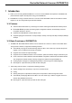
DeviceNet Network Scanner DVPDNET-SL 4 CONFIGURATION OF DVPDNET-SL.................................................................................................... 8 4.1 Configuration through DeviceNet Builder Software ........................................................................... 8 4.1.1 Selection of Communication Channel......................................................................................... 8 4.1.2 Setup of Scan Module ..............................................
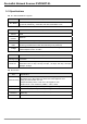
DeviceNet Network Scanner DVPDNET-SL 1 Introduction 1) Thank you for choosing Delta DVPDNET-SL. To ensure correct installation and operation of DVPDNET-SL, please read this chapter carefully before using your DVPDNET-SL. 2) DVPDNET-SL running on the left side of PLC can serve as the DeviceNet master or slave with PLC MPU together. It can be configured through DeviceNet software. 1.1 Features z Serves as DeviceNet master by connecting to PLC MPU and Supports standard DeviceNet protocol.
DeviceNet Network Scanner DVPDNET-SL 1.3 Specifications PLC that DVPDNET-SL supports Item PLC Model Specification DVPDNET-SL supports PLC MPU which can be extendable in its left side g. DVP-SV, DVP-EH2_L, DVP-SX2, DVP-SA2, DVP10MC11T etc.) DeviceNet Interface Item Transmission method Electrical isolation Interface Transmission cable Voltage Specification CAN 500V DC Removable connector (5.08mm) TAP-CB01 cable and TAP-CB02 cable are recommended.
DeviceNet Network Scanner DVPDNET-SL 2 Product Profile & Outline 2.1 Dimension DVPDNET MS NS 4 5 6 3 7 2 8 0 1 x10 1 3 6 7 2 5 9 4 8 0 x10 9 0 1 DR 1 DR 0 IN 1 IN 0 2.2 Product Profiles 1. Model name 2. Extension port 3. Power, MS, NS LED 4. DIN rail clip 5. Digital indicator 6. Extension clip 7. Address switch 8. Function switch 9. DeviceNet connection port 2.3 DeviceNet Connection Port The connector is used on the connection to DeviceNet.
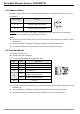
DeviceNet Network Scanner DVPDNET-SL 2.4 Address Switch The switch is used on setting up the node address of DVPDNET-SL on DeviceNet. Range: 00 ~ 63 (64 ~ 99 are forbidden). 0 … 63 Valid DeviceNet node address 64…99 Invalid DeviceNet node address 4 5 6 3 Content 7 Switch setting 2 8 0 5 9 1 4 6 3 7 2 8 9 0 1 Example: If you need to set the node address of DVPDNET-SL to 26, simply switch the corresponding switch of x101 to 2 and the corresponding switch of x100 to 6.
DeviceNet Network Scanner DVPDNET-SL 2.6 Digital Indicator The digital indicator provides the following two functions: DVPDNET POWER MS NS 1) Displaying the node address and error messages of DVPDNET-SL . 2) Displaying the error message of slave. Note: z When the module works normally, the digital displayer will show its own node ID. z When "E1" and "03" are on display continuously, it indicates that the error that "E1" refers to occurs in the slave of node 03.
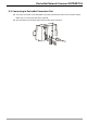
DeviceNet Network Scanner DVPDNET-SL 3 Installation 3.1 Connecting DVPDNET-SL to DVP-SV MPU Adjust the extension clip on the left side of DVP-SV. Meet the extension port of the MPU with DVPDNET-SL as shown in the figure below. Fasten the extension clip. DVPDNET DVP28SV RUN STOP 3.2 Installing DVPDNET-SL and DVP-SV MPU on DIN Rail Use 35mm DIN rail. Open the DIN rail clip on DVP-SV and DVPDNET-SL. Insert DVP-SV and DVPDNET-SL onto the DIN rail.
DeviceNet Network Scanner DVPDNET-SL 3.3 Connecting to DeviceNet Connection Port The colors on the PINs on the DeviceNet connection port match the colors of the connection cables. Make sure you connect the cable to the right PIN. We recommend you also apply Delta’s power module in the connection.
DeviceNet Network Scanner DVPDNET-SL 4 Configuration of DVPDNET-SL 4.1 Configuration through DeviceNet Builder Software Before DVPDNET-SL starts to work normally, it must be configured through DeviceNet Builder software. 4.1.1 Selection of Communication Channel Max 8 DVPDNET-SL modules can be connected to the left side of PLC and every DVPDNET-SL is a communication channel.
DeviceNet Network Scanner DVPDNET-SL 4.1.2 Setup of Scan Module The following dialog is for setting DVPDNET-SL’s current mode: master mode or slave mode. Parameter Master mode Scan interval time Explanation For setting DVPDNET-SL as master mode. The cycle time for master to send and receive the real time data after real-time data connection is successful. Timeouts (EPR) The result value of the parameter multiplied by 4.
DeviceNet Network Scanner DVPDNET-SL 4.1.3 Setup of Scan List Double click the existing icon of DVPDNET-SL in the DeviceNet Builder interface and then the following dialog box appears for configuring the scan module. Parameter Explanation Available node All already scanned slaves appear in “Available list”. After the configuration information is downloaded to DVPDNET-SL, the slave in “Available node” will not conduct the real-time data exchange with DVPDNET-SL.
DeviceNet Network Scanner DVPDNET-SL 4.1.4 Input Table and Output Table Select the device in “Scan list” and then the data length of input and output of the device will be displayed respectively in the lower part of the following dialog box. Parameter Explanation Output Table PLC MPU’s registers and the corresponding output data are shown in “Output list”. The values in PLC’s registers will be sent to slave in real time as the control data of slave.
DeviceNet Network Scanner DVPDNET-SL 4.2 Data Mapping Areas The data mapping introduced in this chapter is the data mapping between PLC MPU and DVPDNET-SL. The mapping relation is unchanged and user has no right to revise this area. Max 8 PLC DVPDNET-SL modules can be connected to PLC’s left side. After all DVPDNET-SL are connected to DVP-SV, DVP-SV will distribute data mapping areas to every DVPDNET-SL.
DeviceNet Network Scanner DVPDNET-SL Note: If the unit No. is 2, the number of the registers above will all be added by 500 respectively; if the unit No. is 3, the number of the registers above will all be added by 1000 respectively; if the unit No. is 4, the number of the registers above will all be added by 1500 respectively and so on. 4.
DeviceNet Network Scanner DVPDNET-SL 5 Sending Explicit Message from Ladder Diagram DVPDNET-SL supports the sending of explicit messages through WPL programs. 5.
DeviceNet Network Scanner DVPDNET-SL 5.2 Structure of Explicit Message You can edit explicit messages in “explicit request message editing area” and “explicit response message editing area”. See the table below for the corresponding relation between the two areas and PLC devices. If you transmit the request message to be sent out to D6250 ~ D6281, DVPDNET-SL will fill the response message to D6000 ~ D6031.
DeviceNet Network Scanner DVPDNET-SL 2) Structure of response message See the table below: Response Message PLC device 15 14 13 12 11 10 9 D6000 Message Header D6001 D6002 D6003 ~ 6031 Message Data 8 7 6 ReqID Status Port Size Service Code MAC ID 5 4 3 2 1 0 Service Response Data The definitions of ReqID, Port, Service Code and MAC ID are the same as their definitions in request message. Size: The length of the message, starting from D6003. Max. 58 bytes.
DeviceNet Network Scanner DVPDNET-SL 4) Application example (I) Target When M0 = On, read Class 1>>Instance 1>>Attribute 1 of IFD9502 1> The connection DV P DNE T DV P 28S V RU N S TOP Node Address:00 DeviceNet Node Address:02 RJ12 Note: IFD9502, a Delta DeviceNet slave module can connect VFD AC motor drive to DeviceNet network.
DeviceNet Network Scanner DVPDNET-SL Explanations on devices PLC device Request message editing area Response message editing area Content Explanation 15 14 13 12 11 10 9 8 7 6 5 4 3 2 1 0 D6250 0101Hex ReqID = 01Hex Command = 01Hex D6251 0005Hex Port = 00Hex Size = 05Hex D6252 0E02Hex Service Code = 0EHex MAC ID = 02Hex D6253 0001Hex High bye of Class ID =00Hex Low byte of Class ID = 01Hex D6254 0001Hex D6255 0001Hex N/A Attribute ID = 01Hex D6000 0101Hex ReqID = 01Hex Sta
DeviceNet Network Scanner DVPDNET-SL 5) Application example (II) Target M1 = On, set 0x99>>Instance 1>>Attribute 2 of IFD9502 to “0004Hex”. 1> The connection Note: IFD9502, a Delta DeviceNet slave module can connect the temperature controller to DeviceNet network. 2> Compulsory settings and explanations on devices Compulsory settings in DVPDNET-SL Parameter Set value Node address 00 Baud rate 500kbps Explanation Set the node address of DVPDNET-SL to “00”.
DeviceNet Network Scanner DVPDNET-SL Explanations on devices PLC device Request message editing area Response message editing area Content Explanation 15 14 13 12 11 10 9 8 7 6 5 4 3 2 1 0 D6250 0101Hex ReqID = 01Hex Command = 01Hex D6251 0005Hex Port = 00Hex Size = 07Hex D6252 0E02Hex Service Code = 10Hex MAC ID = 02Hex D6253 0099Hex High byte of Class ID = 00Hex Low byte of Class ID = 99Hex D6254 0001Hex D6255 0002Hex N/A Attribute ID = 02Hex D6256 0004Hex High byte of da
DeviceNet Network Scanner DVPDNET-SL When M1 = On, DVPDNET-SL will only send out request message once. If you would like it to send out request message again, you will have to change ReqID. When the writing is successfully done, the message responded from the target equipment will be stored in D6000 ~ D6003.
DeviceNet Network Scanner DVPDNET-SL 6 Bit-Strobe Command 6.1 Principle of Bit-Strobe Bit-strobe is one of the standard I/O transmission methods for DeviceNet. The length of command is fixed to 8 bytes (i.e. 64 bits), and every bit corresponds to a slave.
DeviceNet Network Scanner DVPDNET-SL 7 Display of Node Status on Network 7.1 Display of Node Status in Scan List This function is to monitor if DeviceNet slave is offline or not. DVPDNET-SL does read-time monitoring to the nodes in the scan list and maps the status of every node to a bit. You can acquire the node status by monitoring D6032 ~ D6035.
DeviceNet Network Scanner DVPDNET-SL 8 Setup of Slave Mode DVPDNET-SL can serve as slave through modifying of the mode by software. As DVPDNET-SL serves as slave, the default input / output data length is 8 bytes and max input / output data length is 255 bytes. DVPDNET-SL can be set as slave mode in the following method. 1) Connect the devices according to below figure. PC accesses PLC MPU via RS232 or RS485.
DeviceNet Network Scanner DVPDNET-SL 4) Select “Network” => "Online” and the “Select Communication Channel” dialog box will appear. Click on “OK” to start scanning the DeviceNet network after selecting “analog online” in the following window. 5) Select “Network” >> “Scan module” and then “Scan module setting” dialog box appears. After “Slave mode” is selected there, fill the appropriate slave data length. Finally click on “OK” to finish the setting.
DeviceNet Network Scanner DVPDNET-SL 9 Setup of Extended Baud Rate 9.1 Setup of Extended Baud Rate (as master mode) 1) Connect the device to the Devicenet network according to the following figure. PC accesses PLC MPU via RS232 or RS485. DVP DNET-S L DVP28SV DeviceNet Builder 2) Open DeviceNet Builder software and select “Setup” => “Communication Setting” => “System Channel”. And then the following dialog box appears. 3) Set up the communication parameters in the PC and DVP-SV, e.g.
DeviceNet Network Scanner DVPDNET-SL 5) Select “Network” => "Setup of scan module” and the following "Setup of scan module” dialog box appears. Select “Master mode” and “Startup” to activate the function of extended baud rate. In the meanwhile, select the appropriate baud rate according to the actual demand. Click “OK” to finish setting. 6) Select “Network” => “Download” and the following dialog box appears. Click “OK” to download the configuration information to DVPDNET-SL.
DeviceNet Network Scanner DVPDNET-SL 9.2 Setup of Extended Baud Rate (as slave mode) 1) Connect the relevant devices to the DeviceNet network according to the following figure. DVPDNET-SL(Master) DVP28SV DeviceNet Builder DeviceN et DVP28SV DVPDNET-SL(Slave) Note: a. DVPDNET-SL at the bottom of the above figure has been set as slave mode. b. The node addresses of two DVPDNET-SLs must not be repeated. (See section 2.4). c. The baud rates of two DVPDNET-SLs are both 500K bps (See section 2.5).
DeviceNet Network Scanner DVPDNET-SL 3) Set up the communication parameters in the PC and DVP-SV, e.g. the communication port, address, baud rate and communication format. Click on “OK” after configuration is finished.
DeviceNet Network Scanner DVPDNET-SL 6) Set parameter 5 as “Enable” and select the baud rate in parameter 6 in the following page. Click on “Download” to download the newly set parameter value to DVPDNET-SL(Slave). 7) After download is completed, set DVPDNET-SL(Slave)’s function switch: DR0 and DR1 as ON. And then repower PLC to finish the setting of the extended baud rate.
DeviceNet Network Scanner DVPDNET-SL 10 Application Example on Constructing DeviceNet Network In this section, we will present an application example, illustrating how to construct a DeviceNet network and the configuration of the network. Target 10.1 Using an X point of DVP28SV to control RUN/STOP of the remote VFD-L AC motor drive.
DeviceNet Network Scanner DVPDNET-SL 10.2 VFD-L parameter 02-00 Set value Explanation 4 02-01 3 09-00 09-01 09-04 1 1 1 Transmit the frequency of VFD-L via RS485 communication. Control operation of VFD-L via RS485 communication. Set the node address of VFD-L in Modbus to 1. Set the communication rate of VFD-L in Modbus 9600 Set the communication format of VFD-L in Modbus to 7, E, 1, ASCII.
DeviceNet Network Scanner DVPDNET-SL 3> Select “Network” => "Online”, and the “Select Communication Channel” dialog box will appear. Clicking on “OK” starts scanning the DeviceNet network. 4> If the bar on the dialog box does not progress, it means the connection between the PC and DVP-SV is abnormal, or there are other programs also using the COM port on the PC.
DeviceNet Network Scanner DVPDNET-SL 5> Double click on RTU-DNET (node 02), and the "Node Configuration…” dialog box will appear. 6> Click on “IO Configure…” button in “Node Configuration” dialog box, and you will then see “RTU Configuration” page where you click on “Scan IO” button and “Warning” dialog box will appear. Click “OK” then DeviceNet Builder will detect the devices connected to RTU-DNET as below.
DeviceNet Network Scanner DVPDNET-SL 8> In the interface of “Modbus gateway setting”, use the parameters of one slave and fill the relevant values there. You can refer to the user manual of RTU-DNET. Note: The slave here is the slave in Modbus network without direct relation with DeviceNet network. 9> Click on “OK” in the above window and then click on “Download” in the following window to download the configuration data to RTU-DNET. After download is finished, the configuration of RTU-DNET is completed.
DeviceNet Network Scanner DVPDNET-SL 2) Configuration of DeviceNet Master 1> Double click on DNET Scanner (node 01), and the “Scan Module Configuration..." dialog box will appear. You can find the currently available nodes, RTU-DNET and VFD-B Drives 230V 3HP, in the list on the left side. On the right side, there is an empty “Scan List”. 2> (2) Move the slave devices on DeviceNet in the "Available Nodes” list on the left side to the "Scan List” on the right side. Select a node and click on > .
DeviceNet Network Scanner DVPDNET-SL 3> Confirm all the settings and click on “OK”. Next, download the configuration to DVPDNET-SL. If DVP-SV is in RUN mode while you are downloading the configuration, a “Warning” dialog box will appear. 4> Click on “OK” to continue the download. Make sure DVP-SV is in RUN mode. The mapping relation between DVPDNET-SL and slave device is shown as below after configuration of the DeviceNet network following the above steps is completed.
DeviceNet Network Scanner DVPDNET-SL 10.3 Ladder Diagram Program This section introduces how to edit the ladder diagram program to meet the control request of DeviceNet network. Control request When X0=ON, VFD-L AC motor drive runs; When X1=ON, VFD-L AC motor drive stops; After VFD-L has run for 6 seconds and at this time the running frequency still has not reached the designated frequency, Y0 of DVP28SV=ON.
DeviceNet Network Scanner DVPDNET-SL 11 LED Indicator & Trouble-shooting DVPDNET-SL supports two diagnostic methods: indicator diagnosis and digital displayer diagnosis. DVPDNET POWER MS NS 11.1 LED Indicator Diagnosis POWER LED LED status Off Green light on Indication Power is abnormal. Make sure DVPDNET-SL is powered. Power is normal.
DeviceNet Network Scanner DVPDNET-SL MS & NS LED LED status How to correct MS LED Off Off Off Green light on Duplicate ID check has not completed. Red light on Green light on MAC ID detection failure or bus-off Red light on Red light blinking No 24V DC power from DeviceNet network Red light on Red light on 11.2 No power Hardware error Make sure DVPDNET-SL is powered.
DeviceNet Network Scanner DVPDNET-SL Code E2 E3 E4 E5 E6 E7 Indication How to correct Slave device in the scan list does not exist or is offline. 1. Check if there is any change for the node address of the slave. 2. Check if the communication cable is disconnected or connected loosely. DVPDNET-SL fails to transmit a message. Error detected in sequence of fragmented I/O messages from device Slave device returns error when DVPDNET-SL attempts to communicate with it.