
Manual


2
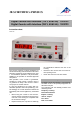
The digital counter with interface can be used as a
stand-alone instrument or together with a Per-
sonal Computer. A Windows programme for
operation and data logging from the instrument
is supplied with the instrument. Also a cable for
connecting the counter and the PC serial port
(COM-1 or COM-2) is supplied.
The Geiger-Müller amplifier module is as stan-
dard supplied with the counter.
The counter with the order number 1003123 is
for mains supplies of 230 V (±10%) while the one
with order no. 1003122 is for 115 V (±10%) sys-
tems.
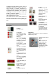
3. Operating controls and connections
Front panel
POWER
On / Off contact
FUNCTION
Push button for selec-
tion of function. Push
to select next.
SELECT
Push button for selec-
tion of measuring
method, and for use
with display of results
START/STOP
Push button to start
and stop of measure-
ment
Hz LED for indication
of measurement in Hz
kHz LED for indication
of measurement in
kHz
s LED for indication of
measurement in sec-
onds
ms LED for indication
of measurement in
milli seconds
4-digit LED-display for
results
2x16-character LCD-
display for function,
selection, setup etc.
A LED
indicator for input A
B LED
indicator for input B
IMPULSE Electrical
impulse input A
IMPULSE Electrical
impulse input B
SWITCH
Electro/mechanical
switch input A
SWITCH
Electro/mechanical
switch input B
PHOTO/MIC
mini-DIN8 socket for
connection of photo
gates or microphone
PHOTO/MIC
mini-DIN8 socket for
connection of photo
gates or microphone
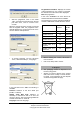
Rear panel
Mains connection 230 V or 115 V AC 50/60 Hz
Mains fuse (0.5 AT)
RS232 interface to PC
für PC
GM
BNC-connector for
Geiger-Müller tube
GM VOLTAGE
Voltage regulation
potmeter for the Gei-
ger-Müller tube.