LIGHT BOX & OPTICAL SET Contents • • • • • • • • 1 Light Box 1 set of 8 color cards 1 Plane mirror 1 Semi-circular mirror 1 Lens biconvex large 1 Rectangular slab 1 Prism 45° 45 °90° 1 Prism 60° 60 °60° • • • • • • • • 2 Slit former plates 1 set of 8 color filters 1 Parabolic mirror 1 Lens biconvex small 1 Lens biconcave 1 Semi-circular slab 1 Prism 60° 30° 90° Spare Lamp Introduction The apparatus consists of a source of light rays and a variety of optical devices that reflect and refract light.
The optical devices (mirrors, lenses, prisms, slabs) should be handled by their finger-grips, so that no smudges or scratches are inadvertently left on the optical faces. The bases of the lenses and prisms are specially finished to provide a background for obscuring the path of light rays. The optical accessory being used should be placed on a plain sheet of paper on which its outline can be marked by running a pencil around its perimeter.
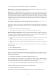
Color of filter used → Color of plate in white light ↓ R W R M O Y G C B V M O Y G C V Index: W-White, R-Red, M-Magenta, O-Orange, Y-Yellow, G-Green, C-Cyan, B-Blue, V-Violet • After familiarizing yourself with the different colors, perform some experiments on your own by observing a color card illuminated by light of one color and viewed in another color. Try to predict your observation before performing the experiment.
2. The incident ray, normal ray and reflected ray, all lie in the same plane. Besides these laws, there are other important features of reflection that we come across every day, i.e., lateral inversion, shaving mirrors, rear-view mirrors etc. Reflection from a Plane Mirror: Adjust the collimating lens so that the resultant beam of light is parallel. Allow a single ray to pass out of the light-box (use a slit plate). Mark its position on the paper. Place the plane mirror in its path, at an angle.
Similarly, if you place the mirror on the dotted line and look at the image of the word below from the bottom of the page, what do you see? --------------------------DI-OXIDE An object is said to be SYMMETRICAL about an axis parallel to the mirror surface if the two halves of the object are mirror images of each other. • Are the above bold words symmetrical? If so, about which axes? Multiple Reflections - Single Mirror: This experiment requires knowledge of refraction.
Rotation of a Plane Mirror: Aim a single ray at the mirror and note the incident ray, mirror position and reflected ray. Rotate the mirror slightly around the incident point and reflected ray. Measure the angle of rotation of the mirror (∠M) and that of the reflected ray (∠R). Repeat this for different angles. • Derive a relation between ∠M and ∠R. The above method is used in various instruments to amplify small changes.
Spherical Aberration F M C Fig. 3 • Are the angles of incidence equal to the angles of reflection? The above problem of improper focusing can be resolved by using a Paraboloid (instead of spherical) or parabolic (instead of circular) mirror. The caustic curve can also be obtained by allowing light from a bulb to fall directly onto the mirror. Parabolic Mirror: In a parabolic mirror, distant as well as near rays focus at the same point. S Reflections From a Parabolic Mirror Fig.
Reflections From X’ A Spherical X F C Convex Mirror Fig. • Place a convex lens (of short focal length) in front of the slits and adjust the convex mirror beyond it until the reflected rays coincide with the incident rays. Draw back these rays to the point where they appear to meet. This point is the center of curvature of the mirror and the distance of this point from the mirror is the radius of curvature (r). P L M Q Fig.
times) until the emergent ray is not deflected. Mark the point of incidence - this is the center of curvature. Shift the light-box so that a single ray strikes the same point of incidence at an angle other than 90°. For different incident angles, mark the rays and half-chords on a circle drawn with the point of incidence at its center. N 1 2 3 r Half Chord Semi-Circular Slab i 3 2 1 N Fig. 7 sin i Half chord i is the same as , as both angles have the equal length hypotenuses.
i1 Incident Ray r1 t i2 d r2 Fig. 8 Emergent Ray Displacement, Parallel-sided Slab: In the previous experiment, ‘d’ in the diagram is the displacement of the emergent ray. For a given angle of incidence, this displacement is directly proportional to the thickness, ‘t’ of the slab. Allow a single ray of light to fall on the shorter side of the slab. Plot the emergent ray on the opposite side and measure d. Also measure the length of the slab, t, and find the ratio d/t.
µ of the slab can also be found by the apparent depth method. µ = real depth/apparent depth. (This is strictly true only when i1 is close to 90°) This phenomenon is observed in day-to-day life when an underwater object appears to be closer to the surface than it actually is. Angle of Minimum Deviation: Allow a single ray to strike a face of a prism and emerge from another face.
r = 90° i r1 Fig. 11 The refractive index of the slab is calculated by µ= sin r 1 = sin i sin i The ∠i at this point is called the CRITICAL ANGLE of the medium and is the minimum angle of incidence for which all light is reflected back into the optically denser substance, instead of emerging into air. • • What do you expect ∠r1 to be? What is it actually? The critical angle for water to air is 49°.
1 2 2 1 Fig. 13 The other prisms can also be experimented with. Try to obtain at least five positions of the three prisms (besides the above two), which result in internal reflection. Trace the ray diagrams, using different color pencils for different rays. • • • Try to set up the three prisms in such a manner that three rays are reflected internally by all three prisms. (Optical-fiber technology is all about repeated total internal reflection).
Dispersion of Colors: Allow a wide beam of light to be incident on one face of the equilateral prism. On a white screen, observe the emergent spectrum for different angles of deviation (from minimum deviation to near-internal reflection). • • • What difference is there between the spectra obtained at minimum deviation and near-internal reflection? (Hint: How many colors are seen in each case?) Why? Would you say that µ is the same r all colors? If not, arrange the colors in order of increasing µ.
Focus - Concave Lens: Allow a set of parallel rays to fall on the concave lens parallel to its axis of symmetry. The rays diverge after refraction. The point from which they appear to diverge is the focus (F) of the lens and OF is the focal length (f). O F Fig. 16 Theoretically, the focal length of a concave lens can be calculated by many methods. Some of them are shown in Appendix 1. However, these methods are not very reliable with the light-box apparatus.
Spherical Aberration: Allow four parallel rays to strike a convex lens, parallel to its axis of symmetry. The inner two and outer two rays meet at different foci. This defect is called spherical aberration. B A Fig. 17 In the figure the parallel rays striking the lens near the edge are bent to a nearer focus, B, than those passing through near the center, which meet at A. The magnitude of the defect, represented by AB in the diagram, is shown greatly exaggerated.
In the set-up for spherical aberration, block the two inner rays and observe the colored foci obtained closely. • Which color has the shortest focal length? Is this in agreement with the dispersion obtained by a prism? (Consider the lens as two prisms placed end-on-end). For more information on aberrations, see Appendix 2. Appendix 1: Determination of Focal Length of a Concave Lens Method 1: Throw the image of a source of light by means of a converging lens on to a screen and note its position.
concave lens. The procedure is to focus the rays from the source by means of the lens, O1, and to locate the image, F. The concave lens is then placed between O1 and the mirror and moved along the axis until an image of S1 is thrown back as close as possible to S1 itself. For this purpose it is convenient to place a source of light behind a small hole on a white screen, and to use the hole as a source so that the image may appear on the screen close beside the hole.
Method 3: Set up a concave mirror behind the lens and a pin in front. An inverted image of the pin will be seen on looking through the lens, and it may be made to coincide with the pin by suitably adjusting the mirror. Appendix 2: The Aberration of Lenses Under ordinary circumstances, a lens or a system of lenses will not produce a perfect image.
rays, which affect the eyes the most, come in between. A screen placed so as to catch the yellow focus would show an image with a purple border, the edges being bluish. The correction of this defect is accomplished by combinations of lenses of different sorts of glass. Flint glass, for instance, spreads the colors apart more widely than does the crown glass. A diverging lens of flint glass placed close to a converging lens can bring the spread colored rays back to parallelism.